Table of Contents
Advertisement
Quick Links
Advertisement
Table of Contents

Related Manuals for Runco DTV-1101


Summary of Contents for Runco DTV-1101
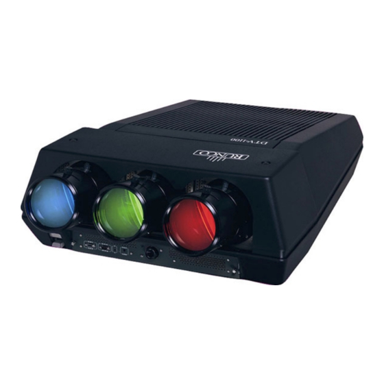
- Page 1 WNER'S PERATING ANUAL 5KFAH 0,68 DTV-1101 DTV Capable CRT Projector...
-
Page 3: Table Of Contents
Table of Contents Table of contents ....................................i Runco Limited Warranty ..................................ii Safety Instructions ................................... 1-1 On safety ....................................1-1 On installation .................................... 1-2 On servicing ....................................1-2 On cleaning ....................................1-2 On repacking ..................................... 1-2 On illumination ................................... 1-2 Location and Functions of Controls ............................... -
Page 4: Table Of Contents
Table of Contents Service Mode ..................................... 7-1 Starting up the Service mode ..............................7-1 Overview flowchart 'Service' mode ............................7-1 Identification ....................................7-2 Copy a Block ....................................7-2 Deletion of Blocks ..................................7-3 Deleting Block by Block ................................7-3 Deletion of All Blocks ................................. 7-3 Change Password .................................. -
Page 5: Runco Limited Warranty
(1) year from the effective date of the warranty (warranty effective date). PARTS: Runco will provide new or rebuilt replacement parts for the parts that fail due to defects in materials or workmanship for a period of one (1) year form the effective date of the warranty. Such replacement parts are then subsequently warranted for the remaining portion (if any) of the original warranty period. -
Page 7: Safety Instructions
Record these numbers in the spaces provided below. Part 15 of FCC rules and EN55022. Refer to them whenever you call your Runco dealer regarding this product. • All the safety and operating instructions should be read before using this unit. -
Page 8: On Installation
Replacement parts - When replacement parts are required, be sure the service technician has used original Runco replacement parts or Green and yellow: ground authorized replacement parts which have the same characteristics as... -
Page 9: Location And Functions Of Controls
Location and Function of Controls LOCATION AND FUNCTION OF CONTROLS REAR PANEL TERMINOLOGY PORT 4/5 RGB + HV) Comp/H sync V sync PORT 6 PORT 3 REMOTE COMMUNICATION . . . Projector Mode: indicates the status of the projector. Communication Port * Not used. -
Page 10: Control Panel Terminology
Location and Function of Controls Control Panel Terminology a. The Local Keypad (built in RCU) Gaining Access The local keypad is built in into the rear of the projector. Push once on the door cover and it will open. It is possible to turn it 90 . PORT 4/5 RGB + HV) This local keyboard has the same functions as the Remote Control... -
Page 11: Connections
Connections CONNECTIONS AC Power (mains) Cord Connection Use the supplied power cord to connect your projector to the wall outlet. Plug the female power connector into the male connector at the front side of the projector. V NOM 120/230 Volt 1 MAX 7/5 Amp FREQ... -
Page 12: Signal Input Connection To The Projector
Connections Start Up with Full White Image. If no action is taken, a white image will be displayed for 20 minutes. This white image will be shifted on the faceplate of the CRT to avoid a CRT burn in. During this warm-up period, it is possible to interrupt this white image projection by pressing the EXIT key. -
Page 13: Connecting A Rgb Analog Source To Port 3
Connections Connecting a RGB Analog Source to Port 3 Connect your RGB source via an interface to Port 3. Always use an interface when a computer and local monitor have to be PORT 4/5 connected to the projector. PROJECTOR MODE RGB + HV) GREEN: operational RED: stand-by... -
Page 14: Connecting A Component Video Source To Port 4/5
Connections Connecting a Component Video Source to PORT 4/5 RGB + HV) Port 4/5 Comp/H sync V sync PORT 6 PORT 3 REMOTE COMMUNICATION . . . A component video source can be connected to the projector via the Port 4/5. The projector detects automatically where the sync signal is located. -
Page 15: Controlling
Controlling CONTROLLING Caution: Do not display a stationary image with full brightness and contrast for longer than 20 minutes, otherwise you risk damage to the CRTs. Battery Installation in the RCU A new battery has been packaged inside the plastic bag with the power cord. -
Page 16: How To Use Your Rcu
Controlling Projector Address The Runco DTV-1101 can be controlled with a. the RCU b. the built-in RCU (local keypad) a. Software set up of the projector address The procedure and results of controlling the projector with either of See 'Change Projector Address' in Chapter 2, 'Service Mode'. -
Page 17: How To Display A Projector Address
Controlling How to Display a Projector Address Analog Picture Controls Press the ADDRESS key (recessed key on the RCU) with a pencil. The analog picture controls can be adjusted with the RCU. The control The projector's address will be displayed in a 'text box'. This text box keys are located on the lower right side of the key panel of the RCU will disappear after a few seconds. -
Page 18: Controlling Chained Projectors
Controlling Controlling Chained Projectors Projectors can be controlled individually as well as in a group. For individual control, see previous pages. For group control of the projectors, see Input Selection and Analog Picture Control. Program the 'zero address' into any RCU. Press on the address key and key in the address ('0') with the numeric keys on the RCU itself. -
Page 19: Start Up Of The Adjustment Mode
(Password protection is only available when the password DIP switch on the controller module is in the ON position. Contact a Runco authorized technician when no password is requested during the adjustment procedure and password protection is desired.) -
Page 21: Random Access Adjustment Mode
Random Access Adjustment Mode RANDOM ACCESS ADJUSTMENT MODE ADJUSTMENT MODE Select a path from below : Starting Up the Random Access Adjustment Mode SOURCE SELECTION ADJUSTMENT MODE EYE Q Push the control disk up or down to highlight "RANDOM ACCESS" and then press ENTER. - Page 22 Random Access Adjustment Mode From previous page From previous page H SIZE V LINEARITY V SIZE BOTTOM BLANKING LEFT RIGHT GREEN ONLY RANDOM ACCESS CONVERGENCE RED ON GREEN ADJUSTMENT MODE BLUE ON GREEN SETUP PATTERN SELECTION FOCUSING GREEN BLUE GREEN BLUE COLOR SELECT RED AND GREEN...
-
Page 23: Selecting Setup Pattern
Random Access Adjustment Mode Selecting Setup Pattern If an external source is connected to the projector, this menu will be displayed. Push the control disk up or down to highlight the desired Choose a setup pattern setup pattern and then press ENTER. from below : SELECTED SOURCE Genlocked pattern: internally generated crosshatch pattern, based... -
Page 24: Random Access Adjustment Mode Selection Menu
Random Access Adjustment Mode Random Access Adjustment Mode Selection Menu This is the main menu for the Random Access Adjustment Mode. Through this menu, the following adjustments and features are accessible: RANDOM ACCESS ADJUSTMENT MODE - Picture Tuning PICTURE TUNING GEOMETRY Sync Slow/Fast CONVERGENCE... -
Page 25: Sync Fast/Slow Adjustment
Random Access Adjustment Mode Sync Fast/Slow Adjustment The sync function is used to minimize horizontal jittering or tearing at the top to the displayed image. Highlight SYNC by pushing the control disk up or down and press ENTER to toggle between FAST and PICTURE TUNING SLOW . -
Page 26: Color Select
Random Access Adjustment Mode Color Select Highlight COLOR SELECT by pushing the control disk up or down RANDOM ACCESS ADJUSTMENT MODE and press ENTER to display the Color Select Menu. PICTURE TUNING GEOMETRY CONVERGENCE FOCUSING COLOR SELECT ENTER continues to the Color Select Menu EXIT will return to Internal Crosshatch Selection or Setup Pattern Selection Menu Select with... -
Page 27: Focusing
Random Access Adjustment Mode Focusing Before starting the focusing adjustment, be sure the lenses are correctly focused. Push the control disk up or down to select FOCUSING RANDOM ACCESS and press ENTER. ADJUSTMENT MODE PICTURE TUNING GEOMETRY CONVERGENCE FOCUSING COLOR SELECT ENTER continues to the Focusing (Color Select) Menu. -
Page 28: Geometry Adjustments
Random Access Adjustment Mode Geometry Adjustments The geometry adjustments have to be done only on the green image. RANDOM ACCESS ADJUSTMENT MODE These adjustments are automatically implemented for the other color PICTURE TUNING GEOMETRY images: Left-right (EW) and Top-Bottom Corrections, Blanking, Hori- CONVERGENCE zontal Amplitude, Vertical Amplitude, Vertical Linearity, and Horizontal FOCUSING... -
Page 29: Raster Shift Adjustment
Press EXIT to return to the Geometry Menu. Note: Horizontal and Vertical shifts for Red and Blue should end up with a setting close to 50%. If these settings are significantly greater or lesser than 50%, then contact a Runco authorized service technician. -
Page 30: Left-Right (East-West) Adjustments
Random Access Adjustment Mode Left-Right (East-West) Adjustments Left-right adjustments affect only the vertical lines of the projected image. Only the green image is displayed while making left-right adjustments. The red and blue images will automatically be corrected in the same manner. Convergence corrections are automatically disabled for the duration of these adjustments. -
Page 31: Seagull Correction
Random Access Adjustment Mode Seagull Correction Use this correction only if, after adjusting the vertical lines with the side bow or side keystone, an 'S' deformation is still visible on the left and GEOMETRY the right side of the image. The default value on the bar scale for this H PHASE RASTER SHIFT correction is 50. -
Page 32: Top-Bottom (North-South) Adjustments
Random Access Adjustment Mode Top-Bottom (North-South) Adjustments GEOMETRY Top-Bottom and center adjustments affect only the horizontal lines of H PHASE the projected image. To start up the Top-Bottom and center correc- RASTER SHIFT tions, follow the next procedure: LEFT-RIGHT (E-W) LEFT SIDE CORRECTION TOP-BOTTOM (N-S) H SIZE... -
Page 33: Seagull Correction
Random Access Adjustment Mode Seagull Correction Use this correction after the image has been adjusted with top and bottom bow and keystone. If a deformation is still visible (like a seagull) GEOMETRY on top and bottom of the image, proceed to the seagull correction. H PHASE Due to interaction, it is possible that the top and bottom bow will RASTER SHIFT... -
Page 34: Vertical Linearity Adjustment
Random Access Adjustment Mode Vertical Linearity Adjustment The vertical linearity adjustment function corrects for vertical non- linearities that extend from the center of the image to the top and GEOMETRY bottom of the image. Push the control disk up or down to highlight H PHASE V LINEARITY on the Geometry Menu and then press ENTER. -
Page 35: Blanking Adjustments
Random Access Adjustment Mode Blanking Adjustments Blanking adjustments affect only the edges of the projected image and are used to frame the projected image on to the screen and to hide or GEOMETRY black out unwanted information (or noise). A 0% on the bar scale H PHASE RASTER SHIFT indicates no blanking. -
Page 36: Convergence Adjustment
Random Access Adjustment Mode Convergence Adjustment Convergence adjustments affect both the horizontal and vertical lines RANDOM ACCESS ADJUSTMENT MODE of the setup pattern. These adjustments are performed on the red PICTURE TUNING GEOMETRY image while superimposed on the green image and then on the blue CONVERGENCE FOCUSING image while superimposed on the green image. -
Page 37: Fine Convergence Adjustment
Random Access Adjustment Mode Vertical Corners To make a coarse adjustment of the red or blue horizontal lines in zone Select with 10, 14, 18, and 22 simultaneously, highlight 'Vertical Corners' and then <ENTER> <EXIT> to return. press ENTER to start the adjustment. COARSE CONVERGENCE HORIZONTAL SIDES VERTICAL CORNERS... -
Page 39: Service Mode
Service Mode SERVICE MODE Starting up the Service Mode Use the control disk to highlight 'Service' and then press ENTER. ADJUSTMENT MODE Some items in the Service Mode are password protected (when the Select a path from below : password function is active). Enter your password to continue. All other GUIDED password protected items will now also be available if you stay in the RANDOM ACCESS... -
Page 40: Identification
Select with - configuration then <ENTER> <EXIT> to return. possible installations: * front-ceiling * front-table DTV-1101 * rear-ceiling * rear-table Proj. address : 001 Soft. Version : 6.00 Config. : Ceiling Front - baud rate PC: transfer speed for communication with an IBM PC Baud Rate PC : 9600 (or compatible) or MAC. -
Page 41: Deletion Of Blocks
Service Mode Deletion of Blocks This item is password protected. The delete function is used to clear all data (settings) from an adjustment block. A delete can be given: SERVICE MODE IDENTIFICATION COPY A BLOCK - block by block DELETE A BLOCK DELETE ALL BLOCKS CHANGE PASSWORD - for all blocks... -
Page 42: Change Password
Service Mode Change Password SERVICE MODE IDENTIFICATION COPY A BLOCK This item is password protected. Highlight 'Change Password' with DELETE A BLOCK DELETE ALL BLOCKS the control disk and press ENTER. CHANGE PASSWORD CHANGE LANGUAGE RUN TIME The current password is displayed. The new password must consist SET TO MIDPOSITION CONVERGENCE MID of 4 digits between 0 and 9. -
Page 43: Set To Midposition
Service Mode Set to Midposition SERVICE MODE IDENTIFICATION This item is password protected. Highlight 'Set to Midposition' with the COPY A BLOCK DELETE A BLOCK control disk and press ENTER to set all settings to their midposition. DELETE ALL BLOCKS CHANGE PASSWORD A confirmation menu will be displayed first. -
Page 44: Dynamic Astigmatism (Spot Shape Adjustment)
Service Mode Dynamic Astigmatism (Spot Shape Adjustment) The spot shape adjustments correct the spot shape in 8 different areas on the screen and for the three colors separately. The spot shape is adjusted according to the axial axises and the diagonal axises when using the arrow keys on the RCU. -
Page 45: G2 Adjust
PROJECTOR WARM UP CRT DRIVE MODE MORE... G2 adjustment should be performed by Runco personnel or Runco authorized dealers. Select with then <ENTER> If you are qualified, press ENTER to continue. If not qualified, press <EXIT>... -
Page 46: Projector Warm Up
Service Mode Projector Warm-Up Highlight 'Projector Warm-Up' by pushing the control disk up or down and press ENTER to select the Projector Warm-Up Menu. SERVICE MODE G2 ADJUSTMENT GAMMA CORRECTIONS The ON/OFF option can be toggled with the ENTER key. CRT RUN IN CYCLE PROJECTOR WARM UP CRT DRIVE MODE... -
Page 47: Memory Banks
<ENTER> This function is intended for customers with a need for various aspect <EXIT> to return ratios, especially those with widescreens. From the Runco factory, three (3) memory banks are assigned for each frequency: Memory Bank 1: 3:4 (1:1.33) Memory Bank 2: widescreen (1:1.78 or l.85) -
Page 49: Messages, Warnings And Failures
Messages, warnings and failures MESSAGES, WARNINGS AND FAILURES When selecting a new source, in- WARNING : INPUT 05 formation about this source will be Fh= 31.5 kHz Message when the entered pass- displayed on the screen. Source invalid Fv= 60 Hz word is wrong. -
Page 51: Specifications
Specifications SPECIFICATIONS Scan Frequency: Horizontal: 15-75 kHz autolock Safety Regulations: Complies with: UL, FCC Class B, Vertical: 37-155 Hz CE, C-Tick Horizontal: 2.5 mS Retrace Time: Environment: 32-104 F (0-40 Vertical: 200 mS Humidity: 0-90% non-condensing Bandwidth: 120 MHz (-3 dB) Storage: 10-122 F (-12-50... - Page 53 RUMA-003800 rev 10-00 2463 Tripaldi Way Hayward, CA 94545 510-293-9154 Fax: 510-293-0201...