Table of Contents
Advertisement
DRYPIX 5000
Operation Manual
8th Edition: July 2008
897N0316F (006-240-70)
This Operation Manual describes details on how to operate the
DRYPIX 5000 and cautions to be observed when operating it. Please
read the Operation Manual thoroughly before actually operating the
DRYPIX 5000 system. After reading this manual, store it nearby the
DRYPIX 5000 so that you can see it whenever necessary.
Advertisement
Table of Contents
Troubleshooting

Related Manuals for FujiFilm Drypix 5000


Summary of Contents for FujiFilm Drypix 5000
- Page 1 8th Edition: July 2008 This Operation Manual describes details on how to operate the DRYPIX 5000 and cautions to be observed when operating it. Please read the Operation Manual thoroughly before actually operating the DRYPIX 5000 system. After reading this manual, store it nearby the DRYPIX 5000 so that you can see it whenever necessary.
-
Page 2: Chapter 1 Introduction
We ask that first-time users read this manual thoroughly before actually using the DRYPIX 5000. After reading this manual, please store it nearby the DRYPIX 5000 so that it may be used to ensure that the machine is used under the best conditions. - Page 3 Contents at a Glance Chapter 1 Introduction Chapter 2 System Overview Chapter 3 Basic Operation Chapter 4 Utility Operation Chapter 5 Troubleshooting Chapter 6 Regular Care and Maintenance Chapter 7 Specifications 006-240-20 2004.03...
-
Page 4: Table Of Contents
Contents Contents Chapter 1 Introduction 1.1 What is the DRYPIX 5000? ..................1.2 System Features ..................... 1.3 Safety ........................1.4 Operational Precautions ..................1.4.1 Laser Handling Precautions ................1.4.2 Preventing Electric Shock ................1.4.3 Ventilation Precautions ................. 1.4.4 Handling Precautions .................. - Page 5 Chapter 4 Utility Operation 4.1 What is Utility? ......................4.2 Starting Up and Quitting the Utility ................4.2.1 Starting Up the Utility ..................4.2.2 Quitting the Utility ..................4.3 Auto F.D.C......................4.4 Test Pattern ......................4.5 Unlock Tray ......................4-12 4.6 Print Queue ......................
-
Page 6: Chapter 6 Regular Care And Maintenance
Chapter 6 Regular Care and Maintenance 6.1 Cleaning the Cleaning Roller with Water ..............6.2 Cleaning the Suction Filter ..................Chapter 7 Specifications 1 System Components ....................Standard Components ..................Options ......................Supplies ......................2 Processing Capacity ....................3 Applicable Film ......................4 Recording Pixel Size .................... -
Page 7: Chapter 1 Introduction
Chapter 1 Introduction 006-240-20 2004.03... -
Page 8: What Is The Drypix 5000
Introduction 1.1 What is the DRYPIX 5000? The Fuji Medical Dry Laser Imager DRYPIX 5000 is a device that prints digital image data transferred via the DICOM network from the FCR Image Reader or CT, MRI and other imaging modalities onto dedicated film in the selected format. -
Page 9: Safety
Introduction 1.3 Safety This section contains safety precautions required for the safe operation of this equipment. Carefully read and follow these precautions before using the equipment. If these precautions are not followed, injuries or damage to the equipment may occur. The safety precautions are marked as WARNING or CAUTION, and additional information “... -
Page 10: Operational Precautions
Wavelength 660 nm Maximum Output 50 mW (CW) The DRYPIX 5000 incorporates a Class 3B laser with a maximum output of WARNING 50mW. To prevent exposure to its laser beams, observe the following precautions. • Never remove the protective covers. -
Page 11: Electromagnetic Compatibility (Emc)
Introduction 1.5 Electromagnetic Compatibility (EMC) This equipment has been tested and found to comply with the limits for medical devices to the EN60601-1-2:1993, Medical Device Directive 93/42/EEC. These limits are designed to provide reasonable protection against harmful interference in a typical medical installation. -
Page 12: Precautions For Storing Or Handling The Di-Hl, Di-Hlc, And Di-Ml Films For The Fuji Medical Dry Laser Imager
Introduction 1.6 Precautions for Storing or Handling the DI-HL, DI-HLc, and DI-ML Films for the Fuji Medical Dry Laser Imager 1.6.1 Precautions for Storing or Handling Unused Films 1 Use only the “Fuji Medical Dry Laser Imager Film DI-HL, DI-HLc, or DI-ML” that is compatible with this equipment. -
Page 13: Other Precautions For Using The Equipment
Introduction 1.7 Other Precautions for Using the Equipment 1.7.1 Precautions for Inserting the Shutter Be sure to turn the power OFF first and then insert the shutter, because a system error may result. Note, however, that you do not have to turn the power OFF if an instruction is indicated on the operation panel to insert the shutter. -
Page 14: Location Of Each Label
Introduction 1.8 Location of Each Label IEC/EN60825-1:2001 Class 3B Panel Label #1 HHS Certification and Identification Label IEC/EN60825-1:2001 Class 1 Product Label IEC/EN60825-1:2001 Class 3B Panel Label #1 Caution Label IEC/EN60825-1:2001 Class 3B Panel Label #2 Mercury-containing Products Label Rating Label IEC/EN60825-1:2001 Class 3B Panel Label #1 006-240-70 2008.07... - Page 15 Introduction High-temperature Cleaning Roller Lever Caution Label High-temperature Operation Caution Label Caution Label Caution Label JAM Handling Label 1 Power Cord Connection Caution Label JAM Handling Label 2 Power Cord Connection Caution Label JAM Handling Label 1 JAM Handling Label 2 Caution Label 006-240-60 2007.03...
- Page 16 Introduction IEC/EN60825-1:2001 Class 1 Product Label IEC/EN60825-1:2001 Class 3B Panel Label #1 FFTPH HHS Certification and Identification Label Cleaning Roller Lever Operation Caution Label High-temperature Caution Label Rating Label Mercury-containing Products Label IEC/EN60825-1:2001 Warning Label IEC/EN60825-1:2001 Class 3B Panel Label #2 1-10 006-240-70 2008.07...
-
Page 17: Chapter 2 System Overview
Chapter 2 System Overview 006-240-20 2004.03... -
Page 18: System Configuration
2.1 System Configuration This system transfers and prints information of images exposed by the FCR Image Reader or CT, MRI and other imaging modalities to the DRYPIX 5000 (this equipment) via the DICOM network. Image data derived from the FCR Image Reader or image processor that is not connected to the DICOM network can be printed via the DRYPIX Link connected to the DICOM network. -
Page 19: Hardware Configuration
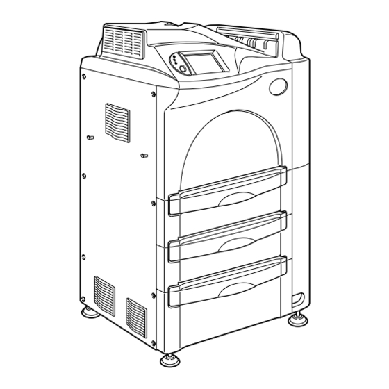
System Overview 2.2 Hardware Configuration [1] DRYPIX 5000 Main Unit [Fig. 2.2] DRYPIX 5000 Main Unit Main Unit Operation Panel Output Film Tray Film Jam Clear Cover Front Cover Tray 1 Tray 2 (option)* Tray 3 (option)* Front Main Power Switch... -
Page 20: Power Cable
System Overview G Power Cable (1) Outside patient environment type: (2) Within patient environment type: (Lock type) 006-240-20 2004.03... -
Page 21: Operation Panel
System Overview [2] Operation Panel [ Fig. 2.3 ] Main Unit Operation Panel ERROR Lamp Display Power SAVE Lamp POWER Lamp Power ON Switch [Table 2-2] Component Names and Function Name Function Power ON Switch Turns ON the power to the main unit. POWER Lamp Lights green when the Main Power Switch has been turned ON. -
Page 22: Chapter 4 Utility Operation
System Overview [Fig. 2.4] Main Unit Operation Panel (display layout: initial image) Title/Message Ready (Green) Utility Icon No. of Prints Standby for Output (Hard Disk Icon) Operation Icon Film Size Icon Shutdown Icon No. of Remaining Films [Table 2-3] Component Names and Functions Name Function Ready (Green) -
Page 23: Chapter 3 Basic Operation
Chapter 3 Basic Operation 006-240-20 2004.03... -
Page 24: Routine Operations
Basic Operation 3.1 Routine Operations The following four steps constitute routine operations. Starting Up the System ............Page 3-3 Reading (Storing) Images ........Page 3-5 Printing Images (film output) ......Page 3-5 Shutting Down the System ........... Page 3-6 need not to be operated on this equipment because connected devices are responsible for those operations. -
Page 25: Starting Up The System
3 When the Power ON Switch is pressed, the initialization process starts. The software version as well as software ID will then appear on the DRYPIX 5000 main unit display. When the following right screen is displayed, the system has been started up normally. - Page 26 Basic Operation [Fig. 3.4] Startup UP Screen - 1 When this screen appears, imaging information can be transferred from an imaging modality to this equipment. [Fig. 3.5] Startup UP Screen - 2 This screen may not appear depending on the temperature inside the equipment, proceeding directly to [Fig.
-
Page 27: Reading (Storing) Images
Because operations, such as film output command, etc., are performed by DICOM- networked devices that enable the DICOM PRINT function, no specific operations are required on the DRYPIX 5000 main unit for film output purposes. However, be sure to observe the following cautions when outputting films from the DRYPIX 5000. -
Page 28: Shutting Down The System
Basic Operation Shutting Down the System 1 Make sure to confirm that the DRYPIX 5000 main unit has completed image recording and output processing and is in idle status. 2 Press the button on the Operation Panel. [Fig. 3.8] Press this button. -
Page 29: Supplying Film (Replacing The Film Pack)
Basic Operation 3.2 Supplying Film (Replacing the Film Pack) When the film in the supply tray runs out, the screen background turns yellow and the button appears. Pressing this button will display the button. An attempt to output films in this status will sound the film supply alarm. * The alarm will not sound if it has been set to OFF. - Page 30 Basic Operation 3 The film tray has been unlocked. See the animation that appears on the display to fully pull the empty film tray out. [Fig. 3.13] Be sure to pull the tray out only after it has been unlocked. WARNING Doing so will result in damaging the tray unit.
- Page 31 Basic Operation 5 Place a new film pack in the empty tray following the procedure below. 5-1 Remove the film pack from the carton. 5-2 With the film pack arrow mark pointing upward, set it in place so that the mark on the label of the film pack is aligned with the mark on the tray as illustrated below.
- Page 32 Basic Operation 5-5 Replace the cutter in the position where it has been placed. 5-6 Slowly push the film tray in until it locks firmly. When locking the film tray, place the hand as illustrated below being careful not CAUTION to pinch your fingers.
- Page 33 Basic Operation 5-8 The display returns to the routine screen. This completes the film supply procedure. Note, however, that if you have selected By each film pack for AUTOMATED F.D.C. in the Utility mode, the Auto F.D.C. (automatic film density calibration) will be performed.
- Page 34 Basic Operation 6-2 When films of unspecified type were loaded When films of unspecified type are loaded, either screen will appear depending on the service setting. 1 When screen A appears: 1-1 To change the film, press the button. 1-2 When the tray is unlocked, fully pull out the film tray toward you. Replace then the film and close the tray.
-
Page 35: Urgent Print
Basic Operation 3.3 Urgent Print This function not only displays print jobs that have already been registered at the time when the Hard Disk Icon was pressed, but also processes urgent printing for specified films. The operation procedure is as follows. 1 Press the Hard Disk Icon on the operation panel. -
Page 36: Deleting A Print Job
Basic Operation 3.4 Deleting a Print Job This function not only displays print jobs that have already been registered at the time when the Hard Disk Icon was pressed, but also deletes those jobs. The operation procedure is as follows. 1 Press the Hard Disk Icon on the operation panel. - Page 37 Basic Operation 3-1 Pressing the button will display the [Fig. 3.27] Confirmation Screen, which prompts you to confirm the setup data. If the input setup data is correct, press the button. The display returns to the [Fig. 3.26] Job List Screen.
-
Page 38: Print Job Details
Basic Operation 3.5 Print Job Details This function not only displays print jobs that have already been registered at the time when the Hard Disk Icon was pressed, but also deletes those jobs or processes urgent printing. The operation procedure is as follows. 1 Press the Hard Disk Icon on the operation panel. - Page 39 Basic Operation 3-1 Pressing the button will display the [Fig. 3.30] Details Screen. [Fig. 3.30] Details Screen Use the buttons to move to the Details Screen of either the previous or following job. If you press the button, the job information will be updated to the newest.
- Page 40 Basic Operation 3-18 006-240-20 2004.03...
-
Page 41: Chapter 4 Utility Operation
Chapter 4 Utility Operation 006-240-20 2004.03... -
Page 42: What Is Utility
Utility Operation 4.1 What is Utility? The DRYPIX 5000 offers Utility functions, which allow the users to operate processing such as film count checking and automatic film density calibration, etc. [ Fig. 4.1 ] Utility Initial Screen (1/3) ......See page 4-4. -
Page 43: Starting Up And Quitting The Utility
Utility Operation 4.2 Starting Up and Quitting the Utility 4.2.1 Starting Up the Utility 1 Press the button that is on the upper right of the routine screen. After a while, the Utility initial screen will be displayed. [ Fig. 4.2 ] Routine Screen [ Fig. -
Page 44: Auto F.d.c
Utility Operation 4.3 Auto F.D.C. This function is used to calibrate the film density. Output film density must correspond to the density gradation curve value that is deter- mined by using the measured 24-step density data as reference. When the film manufacturing (lot) No. has been changed or when the output density has changed, use this function to calibrate the density in the system. - Page 45 Utility Operation At the press of the button, the automatic film density calibration will be performed. Selecting the icon on [Fig. 4.6] Tray Select Screen will enable you to finely adjust a maximum density (Dmax) value. You can use this function when you wish to change the maximum density with respect to the setup value, depending on the view box luminance or room brightness.
- Page 46 Utility Operation For a failure that occurs in automatic film density calibration processing, see Chapter 5, Troubleshooting. [Fig. 4.8] [Fig. 4.9] 5 After approx. three minutes, a 24-step density test pattern film like the following will be output and the AUTO F.D.C will finish. [Fig.
- Page 47 Utility Operation 6 The screen will change to the following (Fig. 4.11). Press the button to return to the Utility initial screen. [Fig. 4.11] AUTO F.D.C. Completed Screen At the press of the button, the display returns to the [Fig. 4.6] Tray Select Screen.
-
Page 48: Test Pattern
Utility Operation 4.4 Test Pattern This function outputs test pattern films. Use this function to output test pattern films as required to make sure that images are printed correctly. The operation procedure is as follows. 1 Start up the Utility. (Refer to section 4.2.1.) 2 Press the button on the Utility initial screen (1/3). - Page 49 Utility Operation 4 On the input modality setting screen that appears, use the buttons to select an input device. Press then the button. [Fig. 4.14] Input Modality Setting Screen “default” is the AE title name registered at the time of shipment from factory.
- Page 50 Utility Operation 6 On the Interpolation select screen that appears, select a desired interpolation type and interpolation algorithm/method. Press then the button. [Fig. 4.16] Interpolation Select Screen If “NONE” is selected for the Interpolation algorithm/method, output test pattern films may not be subjected to interpolation processing and images may be printed smaller in relation to the...
- Page 51 Utility Operation 8 When test pattern film is output after a while, make sure that image has been printed correctly. [Fig. 4.18] Standard Test Pattern (SMPTE) - Example: For an output image 100% 100% SMPTE TEST PATTERN REV. 10 / 6 / 83 © 1983 9 / 6 / 84 When the Service Setting has been performed, a user-defined test pattern can be selected.
-
Page 52: Unlock Tray
Utility Operation 4.5 Unlock Tray When you wish to remove the tray for any reason, you can unlock and remove the tray by using this function. The operation procedure is as follows. 1 Start up the Utility. (Refer to section 4.2.1.) 2 Press the button on the Utility initial screen (1/3). - Page 53 Utility Operation 4 On the tray select screen in step 3 above, select a tray you wish to unlock and press button. The tray will be unlocked. 5 Confirm that the screen has changed to the following. Remove then the tray to conduct necessary work.
- Page 54 Utility Operation 6 After completing the work, insert the tray carefully and confirm that the tray has been locked correctly, and then remove the shutter. When locking the film tray, be careful not to pinch your fingers. CAUTION [Fig. 4.24] 7 Hang the tray on the specified position (on the left-side or rear cover) for storage.
-
Page 55: Print Queue
Utility Operation 4.6 Print Queue You can use this function to delete registered print jobs or handle urgent print processing. The operation procedure is as follows. 1 Start up the Utility. (Refer to section 4.2.1.) 2 Press the on the Utility initial screen (1/3). [Fig. - Page 56 Utility Operation 4 If the button is pressed, jobs selected in step 3 above will be printed urgently. button is pressed, screens like those shown below will appear prompting you to confirm. Press the button. [Fig. 4.28] When the DELETE button was pressed [Fig.
-
Page 57: Set Counters
Utility Operation 4.7 Set Counters This function is used to display (confirm) and/or reset the no. of films output from each tray. The operation procedure is as follows. 1 Start up the Utility. (Refer to section 4.2.1.) 2 Press the button on the Utility initial screen (1/3). - Page 58 Utility Operation 4 Press the button, and the following screen appears. The number of films used since it was cleared off the last and the total number of films used will be displayed respectively for each tray. If the button is pressed on the right hand side of the screen, the number of films used for each tray since it was cleared off the last (displayed at the top) will be cleared off, resetting thus the film count to 0 (zero).
- Page 59 Utility Operation 6 Press the button, and the following screen will appear. [Fig. 4.34] 7 With the button, change the display list. 8 Pressing the button will return to the Set Counters screen [Fig.4.32]. The used film count in the Display List will not be cleared off even if the count is actually cleared off.
-
Page 60: Economy Mode
Utility Operation Economy Mode Economy Mode that consists of the following three patterns is available for saving power consumption by the equipment. Screen Saver Puts off the backlight of the screen and turns the screen OFF. This mode pattern becomes available around-the-clock if you input a specific time period on the “Transition Time”... -
Page 61: Transition Time
Utility Operation 4.8.1 Transition Time Set a time period in which the system proceeds from the routine status to Economy Mode as follows. If the operation panel is not touched or no data comes from the outside exceeding a predetermined time period, the system proceeds automatically to the Economy Mode. The Stand-By/Sleep mode pattern will be activated if settings necessary for “Sched- uler”... - Page 62 Utility Operation 4 When a screen like that shown below appears, press the button. [Fig. 4.37] Details Screen 5 When the button is selected, the display changes to the [Fig. 4.38] screen. If the operation panel is not touched or no data comes from the outside exceeding a time period predetermined on this screen, the system proceeds automatically to the Economy Mode.
- Page 63 Utility Operation CAUTION If you have activated power conservation in “Scheduler” or “Time of Office Closed” and the equipment restored from Economy Mode, the system goes again into Economy Mode when the time preset on the “Transition Time” screen elapses. If you use the system on holidays or at night for emergency purposes, we recommend that you set the “Transition Time”...
-
Page 64: Scheduler
Utility Operation 4.8.2 Scheduler Use the “Scheduler” function to apply Economy Mode at night during weekdays. This function makes it possible to set up a weekly time period for which Economy Mode is to be activated. The time period thus set up will be the “Time Period Where Economy Mode is Activated”. - Page 65 Utility Operation 3 A select screen like that shown below appears. Press the button. [Fig. 4.40] Set Economy Mode Screen 4 When the following screen appears, press the button. [Fig. 4.41] Details Screen 4-25 006-240-20 2004.03...
- Page 66 Utility Operation 5 The display then changes to a screen like that shown below, where you can set up a time period for Economy Mode and None Economy by the day of the week. [Fig. 4.42] Scheduler Screen If the operation panel is not touched or no data comes from the outside exceeding the time period specified so that the Transition Time is effective, the Economy Mode function will be performed.
-
Page 67: Calendar
Utility Operation 4.8.3 Calendar Use the “Calendar” mode function if you wish to save power on office closing days. By using this mode function, you can set up a time range that enables power conservation on a daily basis. This setting also belongs to “Time Period Where Economy Mode is Activated”. - Page 68 Utility Operation The operation procedure is as follows. (If the system has already been proceeded to Economy Mode, you need not to perform steps 1 and 2 below.) 1 Start up the Utility. (Refer to section 4.2.1.) 2 Perform settings necessary for Economy Mode. Press the button on the Utility initial screen (1/3).
- Page 69 Utility Operation 4 The display then changes to the following. [Fig. 4.47] Calendar Screen (1) Press a date of the calendar, and the color of the date thus specified will change, meaning of which are as follows. Repeat touching the screen until the color you want appears. •...
- Page 70 Utility Operation G Time of Office Closed mode settings Each mode pattern (Closing all day, Closing afternoon, or Closing morning) available for office closing days can be set up as follows. [Normal office day] An example of a normal office day with Economy Mode activated from 8:00 to 18:00, according to the Scheduler mode.
- Page 71 Utility Operation The operation procedure is as follows. (If the system has already been proceeded to Economy Mode, you need not to perform steps 1 and 2 below.) 1 Start up the Utility. (Refer to section 4.2.1.) 2 Perform settings necessary for Economy Mode. Press the button on the Utility initial screen (1/3).
- Page 72 Utility Operation 4 The display then changes to the following, where press the button. [Fig. 4.50] Details Screen 5 A screen like that shown below appears. [Fig. 4.51] Time of Office Closed Screen (1) Press a time period value you want to change. Background of a value thus selected will turn white.
-
Page 73: Save Power
Utility Operation 4.8.4 Save Power Use this mode function when you wish to perform power saving immediately. Pressing the button will enable you to proceed immediately to Economy Mode independent of any time periods determined in Economy Mode. The operation procedure is as follows. 1 Start up the Utility. - Page 74 Utility Operation 4 The display then changes to the following screen. Select Stand-By or Sleep mode pattern as necessary. [Fig. 4.54] Save Power Screen : At the press of this button, you can enter Stand-By mode immediately. The screen will then disappear and the power save lamp goes on. To return from the Stand-By mode, touch the operation panel.
-
Page 75: Set Alarm
Utility Operation 4.9 Set Alarm Use this function when you wish to turn ON/OFF or adjust the alarm and button touch tone. The operation procedure is as follows. 1 Start up the Utility. (Refer to section 4.2.1.) 2 Press the button on the Utility initial screen (2/3). - Page 76 Utility Operation [Fig. 4.57] [Fig. 4.58] When was selected. When was selected. Set the button touch tone and volume, then Set the alarm and volume, then press the press the button to determine the button to determine the setup data. setup data.
-
Page 77: Automated F.d.c
Utility Operation 4.10 Automated F.D.C. Use this function to set the timing for achieving automatic film density calibration when supplying a new film pack. The operation procedure is as follows. 1 Start up the Utility. (Refer to section 4.2.1.) 2 Press the button on the Utility initial screen (2/3). -
Page 78: Set Date/Time
Utility Operation 4.11 Set Date/Time The date and time of the clock incorporated in this equipment can be set with this function. The operation procedure is as follows. 1 Start up the Utility. (Refer to section 4.2.1.) 2 Press the button on the Utility initial screen (2/3). - Page 79 Utility Operation [Fig. 4.63] [Fig. 4.64] When was selected. When was selected. Enter a two-digit year (lower two digits of a Enter an hour (two digits) and minutes (two dominical year: 20XX), month (two digits), and digits). Press then the button.
-
Page 80: Software Version
Utility Operation 4.12 Software Version Use this function to display the software version. The operation procedure is as follows. 1 Start up the Utility. (Refer to section 4.2.1.) 2 Press the button on the Utility initial screen (2/3). [Fig. 4.65] 3 The display changes to the software version screen like that shown below. -
Page 81: Reprint
Utility Operation 4.13 Reprint Images stored in the hard disc of the equipment can be reprinted. To use this function, images on the connected equipment to be stored for reprinting purpose must be set up in advance at Service setup. The operation procedure is as follows. - Page 82 Utility Operation 4 The User ID Input screen will appear. Input your User ID (four digits), and press the button. [Fig. 4.69] User ID must be registered at Service setup mode. 5 The Print ID Input screen will appear. Input your Print ID (four digits), and press the button.
- Page 83 Utility Operation 6 The screen Reprint details will appear. [Fig. 4.71] (1) Use the button to set the number of copies. (2) Pressing the button will start registration for print job and display the following screen. [Fig. 4.72] 4-43 006-240-20 2004.03...
- Page 84 Utility Operation (3) When the registration is finished, the Reprint Registration Completed screen will appear. [Fig. 4.73] : Return to the Utility screen. : Returns to the Print ID registration screen. (4) Exit the utility to return to routine mode. When the system has returned to routine mode, reprinting will start.
-
Page 85: Time Interval Determined For Animation Display
Utility Operation 4.14 Time Interval Determined for Animation Display This function changes time interval for display of animation that prompts you to take necessary action such as film loading. The operation procedure is as follows. 1 Start up the Utility. (Refer to section 4.2.1.) 2 Press the button on the Utility Initial screen (3/3). - Page 86 Utility Operation 4 Use the buttons to adjust the animation display speed, and press the button. The animation will then be displayed at a specified speed. 5 If you press the button, the display will change to the ANIMATION (PRE- VIEW) Screen [Fig.
-
Page 87: Chapter 5 Troubleshooting
Chapter 5 Troubleshooting 006-240-20 2004.03... -
Page 88: Items To Be Confirmed First
When the following failure occurs, check the items listed below first and then take appro- priate countermeasures. Error Check Items Countermeasures DRYPIX 5000 1 Whether the Main Power If the Main Power Switch has been does not start Switch on the bottom front of turned OFF, turn it ON (“I”) and then... - Page 89 Check Items Countermeasures The alarm Confirm the operation panel An error window like the following is sounds. display of the DRYPIX 5000. displayed. Press the button to silence the alarm. Then, take an appropriate measure following the error message displayed.
-
Page 90: Error Window
Troubleshooting 5.2 Error Window When an error occurs disabling routine processing to continue, the alarm sounds and an error window like that shown below appears on the display. Press the button to silence the alarm. Jot down the error code and error details code displayed, and then press the button to turn OFF the power. -
Page 91: When The Film Jams
Troubleshooting 5.3 When the Film Jams If the film jams inside the DRYPIX 5000, the alarm will sound and an illustration (seven patterns) that shows the jamming position and then an operation guide animation will appear in the main unit operation panel. - Page 92 Troubleshooting [Table 5-1-2] Illustration Illustration JAM Handling Reference Page for (ALARM ON) (ALARM OFF) Label 1 or 2 Countermeasure Label 1 Page 5-15 Label 1 Page 5-17 Label 2 Page 5-23 – Page 5-25 006-240-20 2004.03...
- Page 93 Troubleshooting Jamming Position: Tray 1 1 The animation starts when the alarm is stopped at the press of the button. See the animation to take appropriate countermeasures. To start the animation while the alarm is set to OFF, press the button.
- Page 94 Troubleshooting 4 Press the button. [Fig. 5.5] 5 Pull out Tray 1 toward you to remove the jammed film. [Fig. 5.6] ➜ Film jams that can be presumed. (1) Part of a film remains outside the tray because it was caught between the tray and the shutter.
- Page 95 Troubleshooting 6 Insert Tray 1 to make sure that it is locked firmly. Close then the front cover. [Fig. 5.7] ➜ 7 Remove the shutter and put it back again on the left-hand side or rear of the equip- ment. [Fig.
- Page 96 Troubleshooting Jamming Position: Tray 2 1 The animation starts when the alarm is stopped at the press of the button. See the animation to take appropriate countermeasures. To start the animation while the alarm is set to OFF, press the button.
- Page 97 Troubleshooting 4 Press the button. [Fig. 5.11] 5 Pull out Tray 2 toward you to remove the jammed film. [Fig. 5.12] ➜ Film jams that can be presumed. (1) Part of a film remains outside the tray because it was caught between the tray and the shutter.
- Page 98 Troubleshooting 6 Insert Tray 2 to make sure that it is locked firmly. Close then the front cover. [Fig. 5.13] ➜ 7 Remove the shutter and put it back again on the left-hand side or rear of the equip- ment. [Fig.
- Page 99 Troubleshooting Jamming Position: 1 The animation starts when the alarm is stopped at the press of the button. See the animation to take appropriate countermeasures. To start the animation while the alarm is set to OFF, press the button. See the animation to take appropriate countermeasures.
- Page 100 Troubleshooting 3 As the animation shows, rotate the handle clockwise to remove the jammed film, then close the front cover. [Fig. 5.16] ➜ ➜ ➜ ➜ ➜ 5-14 006-240-20 2004.03...
- Page 101 Troubleshooting Jamming Position: 1 The animation starts when the alarm is stopped at the press of the button. See the animation to take appropriate countermeasures. To start the animation while the alarm is set to OFF, press the button. See the animation to take appropriate countermeasures.
- Page 102 Troubleshooting 3 As the animation shows, rotate the handle counterclockwise to remove the jammed film, then close the front cover. [Fig. 5.18] ➜ ➜ ➜ ➜ ➜ 5-16 006-240-20 2004.03...
- Page 103 Troubleshooting Jamming Position: 1 The animation starts when the alarm is stopped at the press of the button. See the animation to take appropriate countermeasures. To start the animation while the Alarm is set to OFF, press the button. See the animation to take appropriate countermeasures.
- Page 104 Troubleshooting 3 As the animation shows, open the front cover and/or the small upper cover to remove the jammed film, then close it. [Fig. 5.20] ➜ ➜ ➜ ➜ Proceed to step 3-1. Proceed to step 3-3. Proceed to step 3-2. Proceed to step 3-4.
- Page 105 Troubleshooting 3-1 If you find a jammed film around the position where you have just opened the jam clear cover, press the button. See then the animation to remove the jammed film. [Fig. 5.21] ➜ ➜ ➜ ➜ ➜ ➜ ➜...
- Page 106 Troubleshooting 3-2 If you find a jammed film in the thermal development unit, press the button and see the animation to remove the jammed film. [Fig. 5.22] ➜ ➜ ➜ ➜ ➜ ➜ ➜ 5-20 006-240-20 2004.03...
- Page 107 Troubleshooting 3-3 If you find jammed films both around the position where you have just opened the jam clear cover and in the thermal development unit, press the button. See then the animation to remove the jammed films. [Fig. 5.23] ➜...
- Page 108 Troubleshooting 3-4 If you do not find any film, press the button, and then see the animation to locate and remove a jammed film. [Fig. 5.24] ➜ ➜ ➜ ➜ ➜ ➜ ➜ 5-22 006-240-20 2004.03...
- Page 109 Troubleshooting Jamming Position: 1 The animation starts when the alarm is stopped at the press of the button. See the animation to take appropriate countermeasures. To start the animation while the alarm is set to OFF, press the button. See the animation to take appropriate countermeasures. 2 Open the front cover.
- Page 110 Troubleshooting 3 As the animation shows, rotate the handle clockwise to remove the jammed film, then close the front cover. [Fig. 5.26] ➜ ➜ ➜ ➜ ➜ 5-24 006-240-20 2004.03...
- Page 111 Troubleshooting Ejection Unit Jamming Position: 1 The animation starts when the alarm is stopped at the press of the button. See the animation to take appropriate countermeasures. To start the animation while the alarm is set to OFF, press the button.
- Page 112 Troubleshooting 3 See the animation to remove the jammed film, then close the jam clear cover. [Fig. 5.28] ➜ ➜ ➜ ➜ ➜ 5-26 006-240-20 2004.03...
-
Page 113: Failing In Reading A Barcode
Troubleshooting 5.4 Failing in Reading a Barcode back When a film pack is replaced, this equipment reads a barcode affixed on the of the film pack and manages the film lot number and other information. [Fig. 5.29] Barcode Arrow mark label Film pack The oblique line portion has been... - Page 114 Troubleshooting Press the button to make sure again that a film pack has been set correctly. [Fig. 5.31] [Fig. 5.32] When screen [Fig. 5.32] is displayed, proceed to the following steps on the next page. 5-28 006-240-20 2004.03...
- Page 115 Troubleshooting 1 Input a 20-digit barcode of the label affixed on the back of the bag that contains films, and press the button. [Fig. 5.33] 4924863579513604891 Input this 20-digit figure. 2 If the barcode thus input has been recognized correctly, the display changes to that shown below.
-
Page 116: Failing In Loading Films
Troubleshooting 5.5 Failing in Loading Films For a failure in film replenishment, countermeasures to be taken will differ case by case. Follow the procedures shown below and load films again. 5.5.1 When the tray was closed without placing a new film pack: [Fig. - Page 117 Troubleshooting 5.5.3 When a new film pack was loaded and the tray closed, but the positioning was wrong: [Fig. 5.36] will appear. Since the tray has not been locked, pull out the tray. Place the film pack in the correct position and pull out the film end, and close the tray. [Fig.
- Page 118 Troubleshooting 5.5.5 A new film pack was placed front side back, and the film pack was pulled out of the tray by tearing the label. The bottom of the film pack was then cut, and the tray closed: Since the wrong part was cut off, the film pack cannot be removed. [Fig.
- Page 119 Troubleshooting 5.5.6 When films other than DI-HL, DI-HLc, and DI-ML were placed: (A label on the pack is other than red or green (DI-ML).) (1) Before the film pack is removed: Confirm the color of the film pack label outside of the film tray. If it is not red or green (DI-ML), the film cannot be used in this equipment.
-
Page 120: Failing In Auto F.d.c. (Automatic Density Calibration)
Troubleshooting 5.6 Failing in Auto F.D.C. (Automatic Density Calibration) If fails in automatic density calibration processing for any reason, an error window like that shown below appears. [Fig. 5.44] Press the button to perform automatic density calibration processing again. If the same failure recurs after Auto F.D.C. processing is performed again, a film will be printed by using a density table before the failure has occurred. -
Page 121: Failing In Placing A Cleaning Roller
Troubleshooting 5.7 Failing in Placing a Cleaning Roller When a cleaning roller was not put inside the equipment by mistake, the following error screen ([Fig. 5.46] or [Fig. 5.47]) will appear. The instruction to be displayed on the panel will be different accoding to the alarm setup. [Fig. - Page 122 Troubleshooting 2 When the front cover is opened, the following animation screen [Fig. 5.49] will appear. [Fig. 5.49] 3 Place a cleaning roller and then close the front cover. When the startup ready screen is displayed, the print function will be started. If the error code below is displayed, take the relevant countermeasure to cope with the problem.
-
Page 123: Storing The Equipment Operation History
Troubleshooting 5.8 Storing the Equipment Operation History This equipment is available for storing the operation history in a hard disc incorporated in it. Basically, this function is set to OFF. However, in order to analyze causes of failure, it may be set to ON in service setup mode. -
Page 124: Failing In Turning The Power Switch Off After Pressing The Shutdown Button
Troubleshooting 5.9 Failing in Turning the Power Switch OFF After Pressing the SHUTDOWN Button If the power switch does not turn OFF even when 10 minutes have passed after “System Shut Down” appears, turn the main power switch OFF at the lower right corner on the front of the equipment. -
Page 125: Chapter 6 Regular Care And Maintenance 7
Chapter 6 Regular Care and Maintenance 006-240-20 2004.03... -
Page 126: Cleaning The Cleaning Roller With Water
Regular Care and Maintenance 6.1 Cleaning the Cleaning Roller with Water We recommend that you wash the cleaning roller with water once every week to secure print image quality. When white spots or traces of lint appear on the output film, also clean the cleaning roller with water according to the following procedure. - Page 127 Regular Care and Maintenance 3 Lower the lever and remove the cleaning roller together with its receive. [Fig. 6.2] Removing the Cleaning Roller When removing the cleaning roller, hold it with both hands paying attention not to drop it. Lever Remove the cleaning roller while slightly raising the receive.
- Page 128 Regular Care and Maintenance 5 Use a gauze moistened with alcohol or ethanol anhydride to wipe off water remaining on the roller. The cleaning roller will be dried in a few minutes. 6 Put the roller back to its original position and close the front cover. Do not raise the lever with hand, otherwise a problem such as damages to gears or film stuck may occur with the equipment.
-
Page 129: Cleaning The Suction Filter
Regular Care and Maintenance 6.2 Cleaning the Suction Filter 1 Remove the filter from the left-side cover and use a vacuum cleaner to remove dirt or dust accumulated inside. [Fig. 6.5] Filter 2 Open the front cover and remove the black filter at the bottom. Remove then dirt or dust accumulated inside with a vacuum cleaner. - Page 130 Regular Care and Maintenance 006-240-60 2007.03...
-
Page 131: Specifications
Chapter 7 Specifications 006-240-20 2004.03... -
Page 132: System Components
Specifications 1 System Components 1.1 Standard Components (1) DRYPIX 5000 main unit ........... 1 (One-tray, two-tray and three-tray specification types are available.) (2) Image buffer memory board 256MB ........ 1 1.2 Options Supply film tray, 8"×10" film kit, Add-on memory (256MB), Sorter 1.3 Supplies... -
Page 133: Maximum Density
Specifications 7 Maximum Density For the DI-HL and DI-HLc, select one of 2.64, 3.0, 3.3 and 3.6. For the DI-ML, select 3.6 or 4.0. * Note that 3.6 and 4.0 are for mammography use only. 8 Power Supply Conditions AC100/110/120V ±10% Input voltage Phase Single... -
Page 134: External View And Weight
10 External View and Weight 10.1 External Dimensions and Weight Model Name Width (mm) Depth (mm) Height (mm) Weight (kg) DRYPIX 5000 1240 (including two trays) * Dimensions and weight are approximate and are subject to change without prior notice. [Fig. 7.1] 006-240-30 2005.06... -
Page 135: Internal Construction
Specifications 10.2 Internal Construction [Fig. 7.2] Recording Thermal Dev. Unit Unit Supply Film Tray 1 Supply Film Tray 2 (option*) Supply Film Tray 3 (option*) Interface Main Power Switch * Depending on the equipment specification, Tray 2 is provided as a standard. 006-240-30 2005.06... - Page 136 Specifications 006-240-20 2004.03...
-
Page 137: Maintenance And Inspection
Maintenance and Inspection During maintenance and inspection, strictly observe precautions contained in “1.3 Safety” (page 1-3) and “1.4 Operational Precautions” (page 1-4) in this manual for you to use the DRYPIX 5000 system under best condi- tions. 1 User’s Maintenance and Inspection Items... - Page 138 Maintenance and Inspection 006-240-20 2004.03...
- Page 139 EULA TERMS FOR MICROSOFT WINDOWS® XP EMBEDDED RUNTIME LICENSES You have acquired a device (“DEVICE”) that includes software licensed by [FUJIFILM Corporation] from Microsoft Licensing, GP or its affiliates (“MS”). Those installed software products of MS origin, as well as associated media, printed materials, and “online” or electronic documenta- tion (“SOFTWARE”) are protected by international intellectual property laws and treaties.
- Page 140 SOFTWARE after the date you obtain your initial copy of the SOFTWARE (“Supplemental Components”). • If [FUJIFILM Corporation] provides or makes available to you Supplemental Components and no other EULA terms are provided along with the Supplemental Components, then the terms of this EULA shall apply.
- Page 142 FUJIFILM MEDICAL SYSTEMS U.S.A., INC. 419 WEST AVENUE, STAMFORD CT 06902, U.S.A.