Muratec MFX-2550 Field Engineering Manual
Hide thumbs
Also See for MFX-2550:
- User manual (327 pages) ,
- Printer manual (193 pages) ,
- Manual (45 pages)

Related Manuals for Muratec MFX-2550


Summary of Contents for Muratec MFX-2550
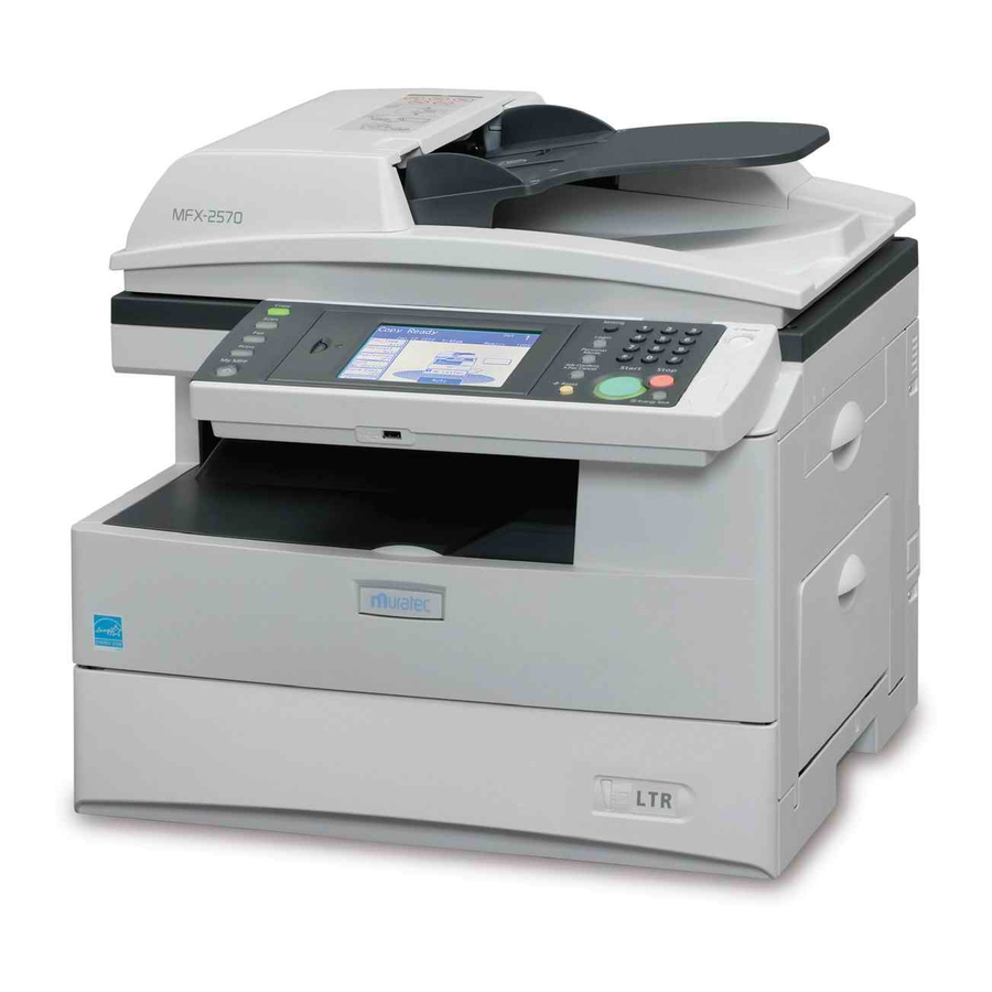
- Page 1 MFX-2550 / MFX-2570 Field Engineering Manual Muratec America, Inc. U.S. Version 4.0...
- Page 2 Battery Precautions Important We do not recommend the independent replacement of the batteries. The batteries are sold only as component parts of the main control board, and cannot be purchased separately from us. Ni- MH (Nickel Metal Hydride) batteries are installed inside the machine as back up memory batter- ies.
-
Page 3: Table Of Contents
Table of contents 1 General Description ................1-1 1.1 Product Description ........................1-1 1.2 Specifications ..........................1-4 2 Machine Composition ................2-1 2.1 Document Scanning Sequence .....................2-1 2.2 Recording Section .........................2-5 2.3 Image Processing ..........................2-7 2.4 Interconnect Block Diagram ......................2-12 2.5 Circuit board constructions ......................2-17 2.6 Sensors ............................2-21 2.7 Function detail and additional information ...................2-23 3 Adjustment Procedures ................3-1... - Page 4 4 Troubleshooting Procedures ..............4-1 4.1 Troubleshooting flow chart ......................4-1 4.2 Initial checks ..........................4-2 4.3 Checkout error ..........................4-3 4.4 Communication tourble .........................4-7 4.5 Image quality problems .......................4-25 4.6 Document trouble ........................4-43 4.7 Recording Paper Jam ........................4-46 4.8 Machine malfunction ........................4-47 5 Maintenance & Adjustment ..............5-1 5.1 Maintenance schedule ........................5-1 5.2 Disassembly procedures .......................5-2 5.3 Adjustment ..........................5-131...
-
Page 5: General Description
1 General Description 1.1 Product Description Name Description ADF cover Open this when a document jams and when cleaning the scanning area. Document guide This supports the document so that it is fed straight. Document tray Load the document here face up. Document output tray Scanned documents are output here. - Page 6 Name Description Platen cover This holds down the document. Document glass Load the document here aligned to the top left of the glass. This is where documents loaded in the ADF (Auto Document Feeder) ADF glass are scanned. The copied or printed paper exits with the printed side down in this tray. Paper exit tray Main power switch This switch is used to turn the machine ON and OFF.
- Page 7 Name Description Toner cartridge Load the toner cartridge here. Charge wire cleaning When the print quality drops, move this rod back and forth to clean the charging wire. Drum cartridge Load the drum cartridge here. When replacing the toner cartridge, push this lever down the left side, Toner cartridge lock lever and then pull out the cartridge.
-
Page 8: Specifications
1.2 Specifications Item Specifications Copy Specifications / General Specifications Scanning method Color CCD Acceptable document size FBS: Max. Legal ADF: Max. Legal Auto document feeder (sheets) Max:80 sheets (Letter/Legal 75g/m2 documents) >Doc. Thickness 0.05 - 0.15mm (Single Sheet) 0.07 - 0.12mm (Multi Sheets) >Doc. - Page 9 Ethernet 10BASE-T/100BASE-TX(Std.) Appearance MFX-2570 : 520×506×473 mm (Std. 2Way/1cassette) >Dimensions (W x D x H) MFX-2550 : 520×506×446 mm (Std. 2Way/1cassette) MFX-2570 : 520×506×593 mm (Max.: 3Way/2cassette) >Dimensions (Max) (W x D x H) MFX-2550 : 520×506×566 mm (Max.: 3Way/2cassette) >Weight (without consumables)
- Page 10 Item Specifications Contrast adjustment >Auto yes, Only Copy mode >Manual (# of levels) yes (5 levels) Automation (w/o photo mode) >Modification for the original document back-ground Document setting position and Scanning Rear left corner Alignment (FBS) Acceptable document size (FBS) >Auto detection >Max.
- Page 11 Item Specifications >PC-Scan (B/W) (Auto,Text,Text/ Photo,photo,Background) 600dpi × 600dpi >>>Optical Resolution 300dpi × 300dpi 200dpi × 200dpi 100dpi x 100dpi Default 300dpi × 300dpi >TWAIN 300dpi × 300dpi >Scan to Folder (SMB) 300dpi × 300dpi >Scan to E-mail 300dpi × 300dpi >Scan to FTP 300dpi ×...
- Page 12 Item Specifications Recording paper size (1st - 2nd Cassette) Letter(SEF), HalfLetter(LEF), Legal(SEF) (Bypass Tray) Letter (SEF), Half-Letter (LEF), Legal (SEF), Executive (SEF), A6 (SEF), A5 (SEF/LEF), A4 (SEF), F4 (SEF), DL (SEF), COM#10 (SEF), Monarch (SEF), Postcard (SEF), Custom Size(width:97-216mm, length:140-356mm) Margin >Copy >>Top/Bottom...
- Page 13 Item Specifications FAX Tx Function Transmission A4 width >Width of document >Length of document 900mm(Normal, Fine, Hfine) 500mm(Ufine) 22 characters ># of TTI >Subscriber ID 20 characters Real-time transmission yes (DADF/ADF only) -When Archiving setting is ON, Scanner TX(RealTime Tx/ Manual Tx) is not be able to use.
- Page 14 Item Specifications Paper Source Setting >Fax/ List Print yes (OFF, ON) >Copy yes (OFF, ON) >PC Print Security Communication Function >Confirmation of Broadcast Destinations >Twice Dialing >Security Reception User Access & Usage Control >Communication Administration yes (ON/OFF) >Copy Administration yes (ON/OFF) >Scan Administration yes (ON/OFF) >Print Administration...
- Page 15 Item Specifications Rx Function Routing Conditions Routing Conditions All received Fax Routing Conditions setting Partial conditions match yes (prefix match/exact match/suffix match/partial match) Multiple conditions(OR) Caller ID Partial conditions match yes (prefix match/exact match/suffix match/partial match) Multiple conditions (OR) Number display Partial conditions match Multiple conditions(OR) ITU-T Subaddress/Password...
- Page 16 Item Specifications Distribution Schedule >Always >Day of the Month setting (Start/End) >Day of the Week setting (Start/End, Every yes (can not specify the day”s” of the week with specified time) week) >Time setting (Start/End) Auto Print of distributed document (ON/OFF) Routing setting operation from machine control panel >Auto Print of distributed document...
- Page 17 Item Specifications Dialing / TEL Function Speed Dial ># of locations 2,000 yes (when pressing the indication button) Auto dial registration name indication Phone line type Pulse/Tone On hook dial Caller ID yes (possible to connect the answering machine) External telephone Phone line Cable Auto Answering Lists...
- Page 18 Item Specifications Font >Latin 136 fonts yes (Option) Printer Controller (PCL5e/XL) Yes(Only Network Connection, Local Connection is not Text Print supported.) Printer Setting >I/O Time-Out setting yes (Default: 300 sec.) >Form Setting[Line/Pages] 5 -128 (Default: Auto) >Resolution 600 / 300 (Default: 600dpi) >CR/LF CR only, LF only/CR=CR+LF, LF=LF/CR=CR, LF=CR+LF/ CR=CR+LF, LF=CR+LF...
- Page 19 Item Specifications >>Windows 7 Enterprise (x86/x64) >>MacOS >>Linux >>UNIX >Required Disk Space for driver installation 10MB and over Scanner Driver yes (TWAIN driver, version 1.9) >Scanning System TWAIN: Scan box type >Document Size setting Letter(SEF), Legal(SEF), H-Letter(LEF) >Document Type setting No conversion/400/300/200dpi (default: No conversion) >Resolution setting >Image Preview...
- Page 20 Item Specifications Transmission protocol SMTP/ESMTP Reception protocol SMTP/POP3 Communication speed Max.100Mbps Encoding MIME/Base64 Document Size A3/B4/A4 (only A4 from the main unit) Communication standard ITU-T T.37 Simple mode Full mode 8dpm×3.85lpm (200×100dpi) Resolution 8dpm×7.7lpm (200×200dpi) 16dpm×15.4lpm (400×400dpi) 600×600dpi Coding method >MH >MR >MMR...
- Page 21 Item Specifications Page mode(1page 1file) Sheet mode(1Sheet 1file) E-mail resend SMTP Authentication Authentication method LOGIN, PLAIN, CRAM-MD5 I-FAX Rx Function Text E-mail Reception English Other Language Languages supported by Latin1 Font Bitmap font 1 style (26dot) Mail Rx with the attachment file TIFF-FX Profile-S Profile-F...
- Page 22 Item Specifications Paper Media Setting Plain, Pasteboard, OHP, Envelope/Postcard (Default: Plain) Cover sheet Sort Print >Electric Sort yes, (Default: Off) Offset yes (MFX-2570 only) *When using paper other than A4, Letter, or Legal size, the machine may not perform the shift sorting function correctly due to environmental variation and paper quality.
- Page 23 Item Specifications yes (PS3 w/ PPD only) >>Mac (10.2, 10.3, 10.4, 10.5) yes (PS3 w/ PPD only) >>Linux (RedHat 9, 3, 4, 5/ SUSE 10.1, 10.2, 10.3, 11/ Fedora 4, 5, 6, 7, 8, 9, 10/ /Tunbo LinuxFUJI 11/ Debian 4) >>Unix >>>Sun Solaris yes (PCL 5e, PS3)
- Page 24 Item Specifications >>Windows Vista Business (x86/x64) >>Windows Vista Enterprise (x86/x64) >>Windows Server 2003 Standard Edition >>Windows Server 2003 Standard x64 Edition yes >>Windows Server 2003 Enterprise Edition >>Windows Server 2003 Enterprise x64 Edition >>Windows Server 2003 Datacenter Edition >>Windows Server 2003 Datacenter x64 Edition >>Windows Server 2008 Standard (x86/x64) >>Windows Server 2008 Enterprise (x86/x64)
- Page 25 Item Specifications >Type (Gateway User) >Company 50 characters >Department Name (User Group Name) 100 characters >Group Name >TEL 40 digits >Fax 40 digits >E-mail Address 50 characters >LDAP Server Login TCP/IP Settings yes (Control panel/Browser) Setting Method TCP/IP Setting IP Address Subnet Mask Gateway Address yes (max.
- Page 26 Item Specifications Copy Document Report Tx Canceled Jobs Archiving Destinations E-mail Address Fax Number Folder FTP Address User File Format of archived document PDF / TIFF-S / TIFF (default: TIFF-S) Index file of archived documents yes, when the network folder is selected as destination (CSV format, up to 1000 logs in 1 file) Data Type Communication Executed Time...
- Page 27 Item Specifications MIB (Management Information Base) MIB support version MIB-2 Standard MIB Information Private MIB Information LDAP Basic Specification LDAP Supported Version Version.2 Version.3 LDAP Operation Search Programmable LDAP Server # of LDAP Server LDAP Setting Parameters Name yes, 23 characters LDAP Server Name yes, 99 characters IP Address...
- Page 28 Item Specifications Search Key Rule Setting Equal Initial Final yes (default) Not Equal Not Any Exist Not Use Operation Interface MFP Control Panel Browser via network yes(Multi Clients) Supported character codes US ASCII UTF-8 yes (Shift JIS, Latin1) Supported directory servers Active directory on Microsoft Windows 2000 server (ENG) Active directory on Microsoft Windows 2003...
- Page 29 Item Specifications Mail Address Relation Acquisition of User Mail Address Windows NT 4.0 Server Windows 2000 Server/Windows Server 2003 yes When the user mail address was not able to be acquired. Use of Mail Address of Equipment From Format displayName<mail> or cn<mail> Network Authentication Settings Automatic Logout Function Support Range of Automatic Logout Time...
-
Page 30: Machine Composition
The register section is for MFX-2570 only. MFX-2550 15 14 13 12 11 10 9 MFX-2570... -
Page 31: Original Detection
Document insert section / separator section The machine scans up to letter paper size document width. Place the document to the center of the document tray and align the document guide. By pressing the start key through copy or transmission commands, the motor starts driving, and the driving force is transferred to the pick up roller through gears, and the document will be fed. - Page 32 2.1.2 Flat Bed Scannser (FBS) section The FBS (Flat Bed Scanner) section consists of document glass (pane), optical reading section, scan- ner frame Assy, and scanner driving section. A lamp (White light LED array) is on the scanner frame, and the light reflected from the document passes through four mirrors and a lends to form a reduced image on CCD sensor as the scanner motor moves the scanner.
- Page 33 Exposure Section: Construction and Function 1 Reflector tape The reflector tape reflects the light from the exposure lamp and supplements its illumination. This helps to lighten the shadow that is made when copying a document not touching the document glass such as a opened book. 2 Exposure lamp A white LED array is used to illuminate the document.
-
Page 34: Recording Section
2.2 Recording Section Recording Paper Feed Path A sheet of the recording paper is separated from the remaining paper by the friction of the pickup roller. The paper is fed along the paper guide until it reaches the register roller. Then it is fed by the rotation of the register roller. - Page 35 Finisher mechanism When finishing the printouts using the shift sort function, every second set of printout will be shifted 1 inch off to the horizontal direction of paper and ejected on the tray. Paper exit direction Shift direction (1 inch) When the trailing edge of paper is nipped only by exit roller pair, the shift motor drives, and the exit roller pair will be shifted to the shift position.
-
Page 36: Image Processing
2.3 Image Processing The image processing is roughly divide into the following steps: 1. Drum Charging 2. Drum Exposure 3. Development 4. Image transfer 5. Fusing 6. Erasing 7. Cleaning Drum charging Fusing Cleaning Exposure Drum Eraser Lamp Image transfer Development 2.3.1 Drum Charge The Drum is charged with corona discharge before LED exposure. -
Page 37: Developing Roller
2.3.3 Development Toner is applied to the invisible static image on the Drum and a toner image is created on the surface. Toner agitator Drum Developing roller Toner supply roller Part Name Function Toner Agitator Agitates toner. Transports the toner to the developing roller. Toner supply Roller Developing Roller Carries the toner to the Drum surface for development. - Page 38 2.3.5 Erasing An LED lamp exposes the Drum surface. When it is exposed the drum charge erases. This helps the drum to be recharged evenly at the next step of charging. Drum LED Lamp 2.3.6 Cleaning The residual toner or paper dust must be removed from the drum. Paper dust is removed from the drum surface by a rubber roller.
- Page 39 2.3.7 Fusing An Overview The toner image transferred on to the paper is securely fixed. A heat roller system is used as the fusing system. The toner image is fused by Heater Roller heated by the Heater Lamp, and securely fixed by the pressure between the Heater roller and Press rollers. A Thermistor detects and controls the Heater Roller temperature.
- Page 40 Fusing Temperature Control Circuit The Thermistor detects the surface temperature of the Heater Roller and inputs that analog voltage into the Main Control PCB. Corresponding to this data, the Heater Lamp ON/OFF signal is output to the Heater ON/OFF switch of the power supply unit, causing the Heater Lamp to turn ON or OFF to control the fusing temperature.
-
Page 41: Interconnect Block Diagram
/SUB_SW DC1-08030-50 123x137 /PEN BUZZ /OPEN2 OPEN2 DCLK Z90-37777-50 LCD3 PANEL KEY2 LCD2 DC1-08040-50 LCD1 LCD0 36.8x137 /PES2 PES2 Z90-37777-50 ASSY SPEAKER /JAMC2 +24V JAMC2 Z90-37777-50 MFX-2590 +24VC PFCL2 MFX-2570 +24VC /PFCL2 COUNTER Z90-48683-00 MFX-2550 /COUNT Z90-35223-50 DCB-D0216-50A Option 2-12... - Page 42 2010.02.24 08-6212- 030-340- 800+ SM30B- P910 P920 SRDS-G- CLK+ DATA1B CLK- DATA10 DATA1A DATA11 /STB DATA19 DATA12 /RST DATA18 DATA13 /PWRDOWN PCB CONN DATA17 DATA14 ROM SCLK LED HEAD DATA16 ROM SDA DATA15 ROM VCC ROM_VCC DATA15 ROM_SDA DC4-08100-50 DATA16 ROM_SCLK DATA14 /PWRDOWN...
- Page 43 LAPS /DRS Z08-05572-00 /DS3 +24VA STAMP /STAMP TXIL /TXIL (ASSY MICRO-SW) DA7-08340-40 LDS1 DS1 (PCB SENSOR) /DS1 DA7-08180-50 46.6x8 LDS2A DS2 (PCB SENSOR) /DS2 DA7-08180-50 46.6x8 MFX-2550 /MADF_B MFX-2590 MADF_B ADF MOTOR MFX-2570 /MADF_A ZA1-02454-50 MADF_A Option /APS Z08-05572-00 2-14...
- Page 44 2010.02.24 +3.3V +3.3V /SHTDWN /PCIINTX /INTB /INTA /INTD /INTC PWE1 PCICLK_S UNIQ /CD1 PCICLK +3.3V /PCIRST BATT /REQ /MRES PWE2 /GNT PAD31 /CE1 PAD30 /CE2 +3.3V /VS1 PAD29 /ATASEL PAD27 /IORD PAD28 PAD25 /IOWR PAD26 CBE3 INTRQ PAD24 Compact Flash PAD23 +3.3V +3.3V...
- Page 45 2010.02.24 +24VA LINE +24VA TEL1 +5VC +5VC (EUR) TEL2 DA7-Y8040-50 CONT24 +12VA (USA) /OH1 DA7-08040-50 /OH2 MAIN 75x140 AREF DC4-08010-50 /DSE2 /DSE1 270.5x220 C(K)DRIVE 1-480425-0 +24VC Option 2-16...
-
Page 46: Circuit Board Constructions
Lithium battery USB Func PROCESSING PROCESSING POWER Layout/Enc. SUPPLY DDR 64MBx3 LED-LAMP (*1) Connected to the Ni-MH battery (*2) Connected to the Lithium battery MFX-2550 PCB MAIN PCB PDL MAIN PCB LPH MOTOR PCB IS Motor Driver DUPLEX DFX336 PCB NCU... - Page 47 Main control board This board controls the MFP system. By inserting the USB memory stick, firmware can be updated. The main devices mounted on the main control board and their functions are as follows: This performs the firmware. This controls the high voltage power board. MD0021 This controls the memory.
- Page 48 LPH (LED Printer Head) board / LPH connection board It detects the printer sensor signal. It controls the clutches. It converts the print serial data received from main control board to a data format for the LED head, then transmits it to the LED. It reads the LED individual difference correction data, and adjust the print density.
- Page 49 High-voltage power board This board generates high-voltage power required for electrophotographic system ; charge, develop- ing, transfer, and cleaning sections. In charging section, it generates positive voltage which is applied to the wire in the drum unit in order to charge the drum surface positive. It monitors the charge condition through the wire condition. Also it charges the mesh grid electrode at the opening of charger in order to make the drum charge potential even.
-
Page 50: Sensors
2.6 Sensors 2.6.1 Sensor Locations The following illustration shows the relative positions of the machine’s sensors. PES1 JAMC2 OPEN2 PES2 DRS * DS3 * Shift * COVER-SW TXIL JAMC1 Thermistor OPEN1 TRAYS *: MFX-2570 only. 2-21... -
Page 51: Sensor Descriptions
2.6.2 Sensor Descriptions The following table gives a brief description of each sensor and its function. Code Name Detects Sensor Type Document sensor 1 Presence of document in feeder Photo interrupter Document sensor 2 Leading and trailing edge of Reflector (MFX-2570) document Photo interrupter (MFX- 2550) -
Page 52: Function Detail And Additional Information
2.7 Function detail and additional information 2.7.1 Port setting list Application Detail Port name Protocol Standard port Application number role New arrival notification to Receive Info Monitor Original UDP/IP 61000 InfoMonitor New arrival inquiry from HTTP/HTTPS TCP/IP 80/443 Send InfoMonitor User list acquisition / User HTTP/HTTPS TCP/IP 80/443... -
Page 53: Adjustment Procedures
3 Adjustment Procedures 3.1 Field Service Program Modes The fax machine feature maintenance modes for machine adjustment. Each mode is listed below along with the command used to activate the mode and a brief functional description. When you press “ * ”, you will hear short beeps. However continue the operation, as there is no prob- lem. - Page 54 Service Program Explanation Operation Page <Setting>, <*>, <2>, <0> 3-119 Life monitor Use this mode to clear the resettable counter maintenance or reenter the life monitor. <Setting>, <*>, <2>, <2> 3-121 Sensor input test This mode enables to confirm the sensor status.
-
Page 55: Machine Parameter Adjustment
3.2 Machine Parameter Adjustment 3.2.1 Setting the Machine Parameters These switches are used to program internal machine parameters. The primary back up battery main- tains these settings if power is lost. 1. From standby, press <Setting>, <*>, <0>, <0>. 2. Press [Edit Parameters]. 3. -
Page 56: Clearing The Machine Parameters
Adujstment Parameter • Image data output level (Data attenuation) • ADF Scanning start position adjustment (Horizontal direction) : MFX-2550 • ADF Elastic rate adjustment (Horizontal direction) : MFX-2550 • ADF Elastic rate adjustment (Vertical direction) : MFX-2550 • ADF Scanning start position adjustment (Vertical direction) : MFX-2550 •... - Page 57 -14.0 dB -15.0 dB Machine Parameter 002 ~ 009 — Factory use only Machine Parameter 010 Switch Initial Adjust Usage/Comments Setting For MFX-2550 76543210 25 steps 00011001 +5.29 mm ADF scanner registration adjustment (Horizontal) 00010000 +3.39 mm Adjusts the start point to 00001000 +1.69 mm...
- Page 58 Machine Parameter 011 Initial Switch Adjust Usage/Comments Setting For MFX-2550 76543210 Adjustment of the scanning 01111111 +1.27% stretching and squeezing for ADF. 00010000 +0.16% (Horizontal) 00000100 +0.04% The plus setting stretches the image data and the 00000000 minus setting squeezes it.
- Page 59 Machine Parameter 013 Initial Switch Adjust Usage/Comments Setting Switch 76543210 Settings For MFX-2550 Leading edge document 127 steps 01111111 +10.76 mm margin adjustment (ADF) 00100000 +2.71 mm Adjusts the leading edge margin from Document 00010000 +1.36 mm Sensor 2 (DS2) to the start of scanning the position.
- Page 60 Machine Parameter 015 Initial Switch Adjust Usage/Comments Setting Switch 76543210 Settings FBS scanner registration adjustment (Horizontal) 127 steps 01111111 +10.76 mm Adjusts the start point to scan the document. 00100000 +2.71 mm The plus setting increases the left margin and the minus 00010000 +1.36 mm setting decreases it.
- Page 61 Machine Parameter 017 Initial Switch Adjust Usage/Comments Setting Switch 76543210 Settings Adjustment of the scanning stretching and squeezing for 76543210 FBS. 01111111 +1.27% (Vertical) The plus setting squeezes 00010000 +0.16% the image data and the 00000100 +0.04% minus setting stretches it. 00000000 Each setting changes by 0.01%...
- Page 62 Machine Parameter 020 Initial Switch Adjust Usage/Comments Setting Switch 76543210 Settings Mirror carriage standby position adjustment 127 steps 01111111 +10.76 mm Adjusts the number of the steps from the home sensor 00100000 +2.71 mm of the mirror carriage OFF to the standby position. 00010000 +1.36 mm 1 step = 2 / 600 dpi...
- Page 63 Machine Parameter 022 Initial Switch Adjust Usage/Comments Setting When you set this switch, set the background level. Set lamp type of DADF 0: Lamp with 32 LED (See page 3-102.) (8 monitoring points) 1: Lamp with 36 LED (9 monitoring points) Factory use only Factory use only Factory use only...
- Page 64 Machine Parameter 025 Initial Switch Adjust Usage/Comments Setting Background level adjustment Switch 76543210 Settings starting position 127 steps 01111111 +10.76 mm Adjusts the number of the steps from the home sensor 00100000 +2.71 mm of the mirror carriage OFF to the background level 00010000 +1.36 mm adjusting start position.
- Page 65 Machine Parameter 030 Switch Initial Adjust Usage/Comments Setting For MFX-2570 76543210 Back side of document 25 steps 00011001 +5.29 mm DADF scanner registration 00010000 +3.39 mm adjustment (Horizontal) 00001000 +1.69 mm Adjusts the start point to scan the document. 00000000 0 mm The plus setting increases the left margin and the minus...
- Page 66 Machine Parameter 033 Initial Switch Adjust Usage/Comments Setting Switch 76543210 Settings For MFX-2570 Back side of document 127 steps 01111111 +10.76 mm Leading edge document 00100000 +2.71 mm margin adjustment (ADF) 00010000 +1.36 mm Adjusts the leading edge margin from Document 00001000 +0.68mm Sensor 2 (DS2) to the start...
- Page 67 Machine Parameter 035 Switch Initial Adjust Usage/Comments Setting For MFX-2570 76543210 Front side of document 25 steps 00011001 +5.29 mm DADF scanner registration 00010000 +3.39 mm adjustment (Horizontal) 00001000 +1.69 mm Adjusts the start point to scan the document. 00000000 0 mm The plus setting increases the left margin and the minus...
- Page 68 Machine Parameter 037 Initial Switch Adjust Usage/Comments Setting Switch 76543210 Settings For MFX-2570 76543210 Adjustment of the scanning stretching and squeezing for 01111111 +1.27% DADF. 00010000 +0.16% (Vertical) The plus setting squeezes 00000100 +0.04% the image data and the 00000000 minus setting stretches it.
- Page 69 Machine Parameter 040 ~ 042 — Factory use only Machine Parameter 043 Initial Switch Adjust Usage/Comments Setting Switch 76543210 Settings For MFX-2550 Leading edge document 127 steps 01111111 +10.76 mm margin adjustment (ADF) 00100000 +2.71 mm Adjusts the leading edge margin from Document 00010000 +1.36 mm...
- Page 70 Machine Parameter 045 Initial Switch Adjust Usage/Comments Setting Switch 76543210 Settings For MFX-2550 Leading edge document 127 steps 01111111 +10.76 mm margin adjustment For FBS 00100000 +2.71 mm Adjusts the leading edge margin after Home Sensor 00010000 +1.36 mm...
- Page 71 Machine Parameter 046 Initial Switch Adjust Usage/Comments Setting Switch 76543210 Settings For MFX-2550 Trailing edge document 127 steps 01111111 +10.76 mm margin adjustment (ADF) 00100000 +2.71 mm Adjusts document feed after the trailing edge of a docu- 00010000 +1.36 mm ment passes Document Sensor 2 (DS2).
- Page 72 Machine Parameter 048 Initial Switch Adjust Usage/Comments Setting Switch 76543210 Settings For MFX-2570 Front side of document 127 steps 01111111 +10.76 mm Leading edge document margin adjustment (DADF) 00100000 +2.71 mm Adjusts the leading edge 00010000 +1.36 mm margin from Document Sensor 2 (DS2) to the start 00001000 +0.68mm...
- Page 73 Machine Parameter 050 Initial Switch Adjust Usage/Comments Setting Switch 76543210 Settings Offset of Gamma Parameter Copy mode 127 steps 11111111 Darkest setting ADF-frontside 126 steps 11111110 Document type: Text/Text&Photo/Photo 2 steps 00000010 1 step 00000001 0 step 00000000 Standard -1 step 00000001 -2 steps 000000010...
- Page 74 Machine Parameter 053 Initial Switch Adjust Usage/Comments Setting Switch 76543210 Settings Offset of Gamma Parameter Copy mode 127 steps 11111111 Darkest setting ADF-frontside 126 steps 11111110 Document type: Text 2 steps 00000010 1 step 00000001 0 step 00000000 Standard -1 step 00000001 -2 steps 000000010...
- Page 75 Machine Parameter 092 Initial Switch Adjust Usage/Comments Setting Able to use the bypass tray When set to “1”, the cassette or the bypass tray is not available for duplex printing. for duplex printing 0: Yes 1: No Factory use only Factory use only Factory use only Factory use only...
- Page 76 Machine Parameter 260 Initial Switch Adjust Usage/Comments Setting Adjust the loop at the synchronizing roller. More loop will correct paper skew, but thin paper may jam easily. Adjust it one step at a time. 4 3 2 1 0 0 1 1 1 1 +5.0 mm Paper loop volume 0 0 1 0 0...
- Page 77 Machine Parameter 280 Initial Switch Adjust Usage/Comments Setting Current adjustment When transfer problems occur, adjust this param- ur, adjust this param- r, adjust this param- this param- eter. Half-letter size Switch 76543210 Settings Plain paper +3.41 mA 31 steps 00011111 +0.88 mA 8 steps 00001000...
- Page 78 Machine Parameter 282 Initial Switch Adjust Usage/Comments Setting Current adjustment When transfer problems occur, adjust this parameter. Switch 76543210 Settings Postcards +3.41 mA 31 steps 00011111 +0.88 mA 8 steps 00001000 The plus setting increases the current and the minus 0 mA ...
- Page 79 Machine Parameter 286 ~ 287— Factory use only Machine Parameter 288 Initial Switch Adjust Usage/Comments Setting Current adjustment When transfer problems occur, adjust this parameter. Switch 76543210 Settings Transparency sheets (OHP) +3.41 mA 31 steps 00011111 +0.88 mA The plus setting increases 8 steps 00001000 the current and the minus...
-
Page 80: Memory Switch Adjustment
3.3 Memory Switch Adjustment 3.3.1 Setting the Memory Switches These switches are used to program internal machine parameters. The primary back up battery maintains these settings if power are lost. 1. From standby, press <Setting>, <*>, <0>, <1>. 2. Press [Mem Switch Edit]. 3. -
Page 81: Clearing The Memory Switches
3.3.2 Clearing the Memory Switches Resets the memory switches to factory defaults. 1. Press <Setting>, <*>, <0>, <1>. 2. Press [Mem Switch Clear]. 3. Press [Yes]. The memory switches will reset to factory defaults. Adjustable items : • CED detection condition •... - Page 82 • V .34 reception • Action at time-out in Fax / tel ready mode • Calling period in Fax / Tel reception mode • Number of HDLC end flags • Digital cable equalizer • Tone detection level • EYE-Q check level at 7200 bps •...
- Page 83 Memory switch 00x : Dialer Memory switch 000 : Initial Adjust Usage / Comments Setting Factory use only — Factory use only — Sets whether the detection should be strict not. CED detection condition Normal Strict 350 ms 500 ms 700 ms 1000 ms Switch 5 DIS detect time after dialing Sets the DIS signal is detected after dialing a number.
- Page 84 Memory switch 00x : Dialer Memory switch 001 : Initial Adjust Usage / Comments Setting Factory use only — Factory use only — Sets whether the detection should be strict or not. DIS detection condition Normal Strict 200 ms 300 ms 400 ms 500 ms Switch 5 Sets the number of seconds the machine waits before dialing PBX mode dial pause...
- Page 85 Memory switch 00x : Dialer Memory switch 004 : Initial Adjust Usage / Comments Setting Factory use only — Factory use only — Factory use only — Factory use only — See table below. DTMF attenuation The setting of this switch is available only when setting other than 0.
- Page 86 Memory switch 00x : Dialer Memory switch 005 : Initial Adjust Usage / Comments Setting Factory use only — Set the time that an incoming ring will not be detected after Ring signal detect time hanging up. (Fax / Tel Ready mode only.) Switch 654 100 ms 200 ms...
- Page 87 Memory switch 01x : Transmission Memory switch 010 : Initial Adjust Usage / Comments Setting Set this switch to “0” if the ring tone of remote unit is mistaken Busy tone detection 0 : No for a busy signal. 1 : Yes Fallback pattern (bps) 2400 4800...
- Page 88 Memory switch 01x : Transmission Memory switch 012 : Initial Adjust Usage / Comments Setting TTI clock type 0 : AM PM clock 1 : 24 hour clock TTI calendor type dd mm yyyy mm dd yyyy (default) yyyy/mm/dd TTI transmit When set at “0”, transmission of the TTI is disabled.
- Page 89 Memory switch 01x : Transmission Memory switch 015 : Initial Adjust Usage / Comments Setting Program individual autodi- Allows individual setting of memory switches 010 as attribute aler attributes 1, 011 as attribute 2, 012 as attribute 3 and 013 as attribute 4 when fax destination are programmed.
- Page 90 Memory switch 01x : Transmission Memory switch 017 : Initial Adjust Usage / Comments Setting Factory use only — Factory use only — Factory use only — Factory use only — Time between ANSam out- When using optical communication line, wait to make sure that put and CM output the terminal adopter has turned the echo-canceler off.
- Page 91 Memory switch 02x : Reception Memory switch 020 : Initial Adjust Usage / Comments Setting Determines the allowable number of erred lines out of total Data error rate lines received in a document. 0 : 10% 1 : 20% A 2100 Hz CED signal disables echo suppression in some Pause one second after telephone equipment.
- Page 92 Memory switch 02x : Reception Memory switch 021 : Initial Adjust Usage / Comments Setting Factory use only — DIS "inch" declaration 0 : No 1 : Yes Factory use only — T1 timer Adjusts the T1 time-out. After the machine dials the remote machine’s phone number, it begins sending CNG and waits 0 : 35 sec 1 : 20 sec...
- Page 93 Memory switch 03x : Modem Memory switch 030 : Initial Adjust Usage / Comments Setting Number of HDLC end flags Defines the number of HDLC end flags. Switch 7654 0000 0001 0010 Initial setting 0011 0100 0101 0110 0111 1000 1001 1010 1011...
- Page 94 Memory switch 03x : Modem Memory switch 032 : Initial Adjust Usage / Comments Setting EYE-Q slice level Setting this bit to “1” enables memory switch 032, bits 0-3 and memory switch 031, bits 0-7 and enables EYE-Q check 0 : Disable 1 : Enable adjustment.
- Page 95 Memory switch 04x : Scanner Memory switch 040 : Initial Adjust Usage / Comments Setting Factory use only — Factory use only — Factory use only — Factory use only — Factory use only — Factory use only — Factory use only —...
- Page 96 Memory switch 05x : Printer Memory switch 050 : Factory use only Memory switch 051 : Initial Adjust Usage / Comments Setting Factory use only — Factory use only — Factory use only — Factory use only — Factory use only —...
- Page 97 Memory switch 06x : Remote reception Memory switch 060 : Initial Adjust Usage / Comments Setting Factory use only — CML relay off time after When dialing from the keypad, phone line noise may occur as the CML relay switches on and off. dialing Set this switch to “0”...
- Page 98 Memory switch 06x : Remote reception Memory switch 062 : Initial Adjust Usage / Comments Setting Factory use only — Factory use only — Factory use only — CNG detect in Ans / Fax When set to “1”, the machine detects the CNG signal in Ans / ready Fax ready.
- Page 99 Memory switch 06x : Remote reception Memory switch 064 : Initial Adjust Usage / Comments Setting Sets the period during which CNG is detected after the TAD CNG detect period after TAD begins recording ICM begins recording incoming message. Switch 7654 Time 0000 0 sec...
- Page 100 Memory switch 06x : Remote reception Memory switch 065 : Initial Adjust Usage / Comments Setting Adjustment of CI detect Sets the time added to or reduced from the CI detect time. time Switch 76543 Time 11111 150 msec 11101 140 msec 01001 40 msec 00111...
- Page 101 Memory switch 07x : Operation Memory switch 070 : Initial Adjust Usage / Comments Setting The number of error lines contained in the received Display error line data will be shown in the LCD. 0 : No 1 : Yes Allows fax communication to be heard through the Tonal line monitor monitor speaker.
- Page 102 Memory switch 07x : Operation Memory switch 071 : Initial Adjust Usage / Comments Setting Factory use only — Factory use only — Print TCR with the original For easy identification, the first page of a document stored for memory transmission will print along a TCR when the trans- page during memory trans- mission when the result is mission result is NG.
- Page 103 Memory switch 07x : Operation Memory switch 076 : Initial Adjust Usage / Comments Setting Adjust this setting when a private exchanger disconnects the Timing to turn off the S- line when S-Relay is turned off. Relay at fax reception. 7654 time 1111...
- Page 104 Memory switch 09x : Miscellaneous Memory switch 090 ~ 096 : Factory use only Memory switch 097 : Initial Switch Adjust Usage/Comments Setting Day light saving time This switch sets the month when the day light saving (Summer time) start month time (summer time) begins.
- Page 105 Memory switch 09x : Miscellaneous Memory switch 098 : Initial Switch Adjust Usage/Comments Setting Day light saving time This switch sets the month when the day light sav- (Summer time) end month ing time (summer time) ends. Switch 7 6 5 4 Time 0 0 0 0 October...
-
Page 106: Setting Individual Autodialer Attributes
3.4 Setting Individual Autodialer Attributes This function allows the user to configure an individual address book entry with the settings shown in Memory Switches 010, 011, 012, 013 and 014. To set the individual attributes: 1. Change memory switch 15, bit 7 to “1”. (See “3.3.1 Setting the Memory Switches” for more informa- tion on changing memory switch 015.) 2. - Page 107 Attribute 1 - Individual Autodialer Setting (Equivalent to Memory Switch 010) Initial Switch Adjust Usage/Comments Setting Sets this switch to “0” if the ring tone of remote unit Busy tone detection 0: No is mistaken for a busy signal. 1: Yes Fallback pattern (bps) 2400 4800...
- Page 108 Attribute 2 - Individual Autodialer Setting (Equivalent to Memory Switch 011) Initial Switch Adjust Usage/Comments Setting The time between reception of CFR and transmission of data When CFR and data overlap due to line echo, increase the interval between CFR and data transmission using this switch.
- Page 109 Attribute 3 - Individual Autodialer Setting (Equivalent to Memory Switch 012) Initial Switch Adjust Usage/Comments Setting TTI clock type 0 : AM PM clock 1 : 24 hour clock TTI calendor type dd mm yyyy mm dd yyyy (default) yyyy/mm/dd TTI transmit When set at “0”, transmission of the TTI is disabled.
-
Page 110: Unique Switch Adjustment
3.5 Unique Switch Adjustment 3.5.1 Setting the Unique Switches These switches are used to program internal machine parameters. The primary back up battery maintains these settings if power is lost. 1. From standby, press <Setting>, <0>, <4>. 2. Press [Switch Edit]. 3. -
Page 111: Clearing The Unique Switches
3.5.2 Clearing the Unique Switches Resets the unique switches to factory defaults. 1. From standby, press <Setting>, <0>, <4>. 2. Press [Switch Clear]. 3. Press [Yes]. The unique switches will reset to factory defaults. 4. Press <Reset> to return the machine to standby. Adjustable items : •... - Page 112 • 3429 baud symbol rate when communicating at V.34 • 3200 baud symbol rate when communicating at V.34 • 3000 baud symbol rate when communicating at V.34 • 2800 baud symbol rate when communicating at V.34 • 2400 baud symbol rate when communicating at V.34 •...
- Page 113 Unique Switch 00x : Dialer Unique Switch 000 : Initial Switch Adjust Usage/Comments Setting Factory use only Time to output simulated ring Adjust the time from income to output ring tone. (The tone time to detect CED) 6 5 4 1 1 1 4.9 seconds 1 1 0...
- Page 114 Unique Switch 00x : Dialer Unique Switch 003 : Initial Switch Adjust Usage/Comments Setting Factory use only Set this switch to “0” to display all dial history on the Display only direct input redial list. Set this switch to “1” to display only direct number on redial list 0: Yes input number on the list.
- Page 115 Unique Switch 01x : Transmission Unique Switch 010 : Initial Switch Adjust Usage/Comments Setting Factory use only Factory use only Factory use only Factory use only Including TTI inside the Setting this bit to “0” transmit the document length added with the TTI. Setting it to “1” transmit the document length including TTI inside the document.
- Page 116 Unique Switch 01x : Transmission Unique Switch 015 — Transmission Initial Switch Adjust Usage/Comments Setting Factory use only Factory use only Not used Factory use only Factory use only Factory use only Factory use only Determine I the handshaking will be done with V.8 V.8 handshake in real time recommendation if real time transmission.
- Page 117 Unique Switch 01x : Transmission Unique Switch 017 : Initial Switch Adjust Usage/Comments Setting Factory use only Factory use only Factory use only Factory use only Factory use only Factory use only Determines if the JBIG transmission is available. JBIG transmission 0: No 1: Yes Factory use only...
- Page 118 Unique Switch 01x : Transmission Unique Switch 019 : Initial Switch Adjust Usage/Comments Setting Factory use only Factory use only Factory use only Factory use only Switch 4 3 2 1 0 Settings Number of redial times for archive transmission 0 0 0 0 0 time 0 0 0 1...
- Page 119 Unique Switch 02x : Reception Unique Switch 020 : Initial Switch Adjust Usage/Comments Setting Factory use only Factory use only Factory use only Transmit CED signal Determines if sending CED signal. 0: No 1: Yes Pseudo-ring start time Sets the time the pseudo-ring begins after answering an incoming call.
- Page 120 Unique Switch 02x : Reception Unique Switch 022 : Initial Switch Adjust Usage/Comments Setting Document storage method JBIG Initial setting IMAGE MMR reception Used to determine the encoding method at DIS 0: No declaration. 1: Yes JBIG reception Used to determine the encoding method at DIS 0: No declaration.
- Page 121 Unique Switch 02x : Reception Unique Switch 029 : Initial Switch Adjust Usage/Comments Setting Factory use only Set this switch to “1” will delete the message Displays the message “No Network Connection.” “No Network Connection.” Use this switch if the machine is not used in a network.
- Page 122 Unique Switch 03x : Modem Unique Switch 030 : Initial Switch Adjust Usage/Comments Setting Factory use only Factory use only 3429 baud symbol rate when If the error frame often occurs because of the symbol rate is too high, setting this switch to communicating at V.34 “1”...
- Page 123 Unique Switch 03x : Modem Unique Switch 032 : Initial Switch Adjust Usage/Comments Setting Factory use only Factory use only Factory use only Factory use only Factory use only The time limit to output the ANSam (A sinewave ANSam output time signal at 2100 Hz amplitude-modulated).
- Page 124 Unique Switch 03x : Modem Unique Switch 037 : Initial Switch Adjust Usage/Comments Setting Factory use only Factory use only Factory use only If retraining occurs due to the low reception signal The delay before post- level and few delay of the telephone line, it may message is transmitted overlap the second post-message.
- Page 125 Unique Switch 04x :Scanner Unique Switch 040 : Initial Switch Adjust Usage/Comments Setting Factory use only Show the lamp in error. 0: FBS lamp error 1: DADF lamp error Factory use only Factory use only Factory use only Factory use only Factory use only Factory use only Unique Switch 041 ~ 042 --- Factory use only...
- Page 126 Unique Switch 04x :Scanner Unique Switch 045 : Initial Switch Adjust Usage/Comments Setting This switch is a measure to avoid document jam Enable measures for false that occurs when documents with punch holes are detection of punch holes as a document leading edge scanned.
- Page 127 Unique Switch 05x : Printer Unique Switch 050 : Initial Switch Adjust Usage/Comments Setting Factory use only Factory use only Factory use only Factory use only Smoothing in Hyper-Fine Smooths the data scanned in each resolution mode. (400 x 400 dpi) mode 0: No 1: Yes Smoothing in Super-Fine...
- Page 128 Unique Switch 05x : Printer Unique Switch 053 : Initial Switch Adjust Usage/Comments Setting Switch 76543210 Settings Printer density adjustment. 00000000 Not available 00000001 Lightest 00000010 00000011 00000100 Normal Initial setting 00000101 00000110 00001001 Darkest 00001011 Not available ↓ Unique Switch 054 ~ 059 —...
- Page 129 Unique Switch 06x : Remote reception Unique Switch 060 ~ 066 — Factory use only Unique Switch 067 : Initial Switch Adjust Usage/Comments Setting Factory use only Factory use only Factory use only CNG detection during OGM output in ANS Ready 0: Yes 1: No Number of detection DTMF...
- Page 130 Unique Switch 07x : Operation Unique Switch 070 — Factory use only Unique Switch 071 : Initial Switch Adjust Usage/Comments Setting Line monitor in Quick memory transmission 0: Off 1: On Factory use only Factory use only Factory use only Factory use only Factory use only Retrieve the document received in the memory by...
- Page 131 Unique Switch 07x : Operation Unique Switch 075 : Initial Switch Adjust Usage/Comments Setting Factory use only Factory use only Factory use only Factory use only Journal list printing order 0: From old history 1: From new history Key press time to activate Set how long to press <Energy Save>...
- Page 132 Unique Switch 07x : Operation Unique Switch 077 : Initial Switch Adjust Usage/Comments Setting Print timeout on PCL text 7 6 5 4 printing (at local printing) 1 1 1 1 15 seconds 1 1 1 0 14 seconds 1 second/step 1 1 0 1 13 seconds Adjustable range: 1~15...
- Page 133 Unique Switch 07x : Operation Unique Switch 079 : Initial Switch Adjust Usage/Comments Setting Print timeout on PCL (at local 7 6 5 4 printing) 1 1 1 1 75 seconds 1 1 1 0 70 seconds 5 seconds/step 1 1 0 1 65 seconds Adjustment range: 5~75 1 1 0 0...
- Page 134 Unique Switch 08x : Miscellaneous Unique Switch 080 — Factory use only Unique Switch 081 : Initial Switch Adjust Usage/Comments Setting Factory use only Factory use only Print dialing error on journal 0: No 1: Yes Factory use only Factory use only Factory use only Factory use only Factory use only...
- Page 135 Unique Switch 08x : Miscellaneous Unique Switch 085 — Miscellaneous Initial Switch Adjust Usage/Comments Setting Factory use only Print/Send the consumable order sheet when the drum is NOTE near end 0: Yes For this feature to work correctly, you must 1: No register several items.
- Page 136 Unique Switch 09x : Miscellaneous Unique Switch 090 ~ 094 — Factory use only Unique Switch 095 : Initial Switch Adjust Usage/Comments Setting Factory use only Factory use only Factory use only Factory use only Factory use only Factory use only F4 paper length Set the F4 paper length Switch 1 0...
- Page 137 Unique Switch 09x : Miscellaneous Unique Switch 099 : Initial Switch Adjust Usage/Comments Setting Factory use only Factory use only Factory use only Factory use only Factory use only Factory use only Factory use only Enable Quick TWAIN You can enable “Quick TWAIN” instead of the 0: No standard TWAIN box operation.
-
Page 138: Clear Programmed Data / User Settings
3.6 Clear Programmed Data / User Settings User programmed information such as address book entries, date, time, Transmit Terminal Identifier (TTI), Subscriber ID, etc., are stored in the unit’s Random Access Memory (RAM) and on the CF memory card that is attached to the network board. This function does not clear the machine parameters, memory switches and unique switches. -
Page 139: Monitor
3.8 T.30 Monitor In all binary coded facsimile control procedures the HDLC frame structure is utilized. The basic HDLC structure is shown below. Preamble Binary coded information Non-standard facilities frame(NSF) Called subscriber identification frame (CSI) Digital identification frame (DIS) Facsimili Facsimili Frame Flag... - Page 140 3.8.3 How to see the print out (Example for fax transmission) (Example for fax reception) TxFrame : Signals sent by machine printing T.30 report RxFrame : Signals received from remote machine DATA: Additional 8-bit octet information to clarify facsimile procedures. In the list, the data are in hexadecimal digits.
- Page 141 NSF, NSC, NSS: NSF, NSC, NSS are nonstandard unit frames. The first three bytes of the FIF are specified by T.30. The subsequent digits are individually determined by the manufacturers. The first byte refers to the country code. The second byte is a spare; it is 00 (hex) presently. The third byte is the manufacturer code.
-
Page 142: Printer Maintenance Mode
A transmission with PPR signal: The error frame in fax reception is identified using the post-message signal and PPR signal. TxFrame RxFrame D A T A PPS MPS BF 4F 00 00 0F BC F0 00 FF FF FF FF FF FF FF FF FF FF FF FF FF FF FF FF FF FF FF FF FF FF FF FF FF FF FF FF FF In PPS signal FIF, the pages, blocks and frames are displayed one value less than the real value. - Page 143 4. Press [Yes]. 5. If you’ve replaced the transfer roller, select [Replace Transfer Belt]. 6. Press [Yes]. The machine goes back to standby mode. 3.9.2 When “Checkout error : XX” message is displayed To access the printer maintenance modes for determine the cause of the “Checkout error : XX” error message.
- Page 144 4. Select [ON] and press [Enter]. 5. Select [E-mail Mail Address 1]. 6. Enter the e-mail address and press [Enter]. 7. To send the service report to another location, press [E-mail Address 2] and/or [E-mail Address 3] and enter the location. Otherwise, skip to step 8. 8.
-
Page 145: Service Report Printing
3.10 Service Report Printing You can print out a report that contains machine’s usage and error history. 3.10.1 Printing the Service Report 1. From standby, press <Setting>, <*>, <0>, <7>. 2. Select [ON] or [OFF] for each settings, and press [Yes]. 3.10.2 Contents of the service report NOTE Some device on the service report may not be equipped on your machine. - Page 146 First page of the report. Detail • Paper size per unit • Number of total printed pages • Number of pages printed on current drum (I/C) • Number of pages printed after the resettable counter is cleared and the cleared date. Number of printed pages based on counter calculating procedure (Four legal size paper is counted five letter size paper) Printer trouble information (Total pages and the pages after the resettable counter is...
- Page 147 Second page of the report Detail Number of printed pages per paper size and print job. • Total printed pages • Total printed pages on current drum (I/C) Number of printed pages per paper media and mode. Number of page per optional device and print job. Number of scanned pages per document size and mode 3-95...
- Page 148 Third page of the report Detail Number of communication times per communication type Number of PC scan times Number of times advanced functions used Number of customer registered information Machine set-up information Number of fax communication error per error code Number of internet-fax communication error ( for engineer only) 3-96...
- Page 149 Fourth page of the report Detail 20 latest scanner error histories 20 latest printer error histories 20 latest printer jam histories ( for engineer only) Fifth page is for engineer only. 3-97...
-
Page 150: Monitor Speaker
3.11 Monitor speaker If you need to monitor the signal of fax communication, turn this mode to on. You can hear the signal sound with machine’s speaker during fax transaction. 1. Press <Setting>, <*>, <0>, <8>. 2. Select the monitor type from [ON until DIS] or [ON]. 3. - Page 151 Display Item Detail Toner Recycled Number of times toner cartridge is replaced Toner cartridge working time (x 10 seconds) Toner Life After Replaced Total printed pages on current toner cartridge Total printed pages since "Toner near end" warning is After Caution displayed Fuser Replaced Number of times fuser is replaced...
-
Page 152: Printer Test
3.12.2 Printer Test The Printer Test mode offers seven different test patterns as shown below. Checkered Squares Paper Scum Halftone Halftone2 White Black Ladder LED Head Test 6% Pattern 1. Press <Setting>, <*>, <0>, <9>, then select [Test Pattern Print]. 2. -
Page 153: Feeder Test
3. Select a cassette or tray that holds your desired paper size to test, and press [Enter]. 4. Enter the numbers of pages to print and press [Enter]. 5. Press [Yes]. The selected pattern will be printed continuously. Press <Stop> to stop printing. 3.12.3 Feeder test The feeder test discharges all documents in the automatic document feeder (ADF) at a constant speed and displays the document total in the LCD. -
Page 154: Set Background Level
The Set Background Level mode allows the level to be set without erasing memory contents. 1. Press <Setting>, <*>, <0>, <9>, then select [Background level]. 2. Select the scanner to adjust. On MFX-2550, only [Front] is available. 3. Press [Start]. - Page 155 3. Set the chart on FBS (Flat Bed Scanner), and press [Make for FBS]. (Set the chart so that scanning starts from the chart top.) 4. Set the chart on ADF, and press [Make ADF/F] or [Make ADF/B]. On MFX-2550, [Make ADF/B] is not available.
-
Page 156: Print Machine Parameters, Memory Switch And
3.13 Print Machine Parameters, Memory Switch and Unique Switch Settings This function instructs the unit to print a list of the machine parameter, memory switch and unique switch settings. The list shows the default and current settings for each. 1. Press <Setting>, <*>, <1>, <0>. 2. -
Page 157: Led Test
3.14.1 LED Test 1. Press <Setting>, <*>, <1>, <1>, then select [LED Test]. 2. Press <Start>. Every time you press <Start> the LED illuminates in the following order: Green Red Blue All LEDs ON All LEDs OFF 3. -
Page 158: Key Panel Test
3.14.3 Key Panel Test 1. Press <Setting>, <*>, <1>, <1>, then select [Panel Test]. 2. As each button on the keypad is pressed, a representative name as show in the following table will be dis- played. Indication in LCD Indication in LCD Copy Copy Personal Mode... -
Page 159: Dram Check
1. Press <Setting>, <*>, <1>, <1>, then select [Page Memory check]. 3. Select the desired checking area. On MFX-2550, only [Scanner front memory area] is available. 4. The machine starts checking and the result (OK/NG) will be shown in the display. - Page 160 3.14.8 Pseudo ring test 1. Press <Setting>, <*>, <1>, <1>, then select [Pseudo ring test]. 2. Press [Start], to ring the bell. 3. Press [End] to stop. 4. Press [Close] to complete the pseudo ring test. 3.14.9 Serial number writing This test mode is not applicable to field service of this machine.
-
Page 161: Line Tests
3.15 Line Tests This mode offers several internal tests and ability to monitor certain unit output functions. Included are relay tests, modem signal output monitoring, and DTMF output monitoring. NOTE To monitor the tones, an external monitoring device must be connected to the telephone line jack. 3.15.1 Relay Test This mode tests the on/off operation of various relays and switches. -
Page 162: Tonal Signal Test
3.15.2 Tonal Signal Test The tonal signal test permits the unit’s output tones to be monitored. 1. Press <Setting>, <*>, <1>, <2>. 2. Press [Tonal]. 3. Select your desired tonal signal test. When it is selected, it will be highlighted. Refer to the table below. -
Page 163: Dtmf Output Test
3.15.3 DTMF Output Test The DTMF output test permits the unit’s DTMF tones to be monitored. 1. Press <Setting>, <*>, <1>, <2>. 2. Select [DTMF]. 3. Select your desired tonal DTMF tone. When it is selected, it will be highlighted. Display Signal Display... -
Page 164: Mirror Carriage Transfer Mode
3.16 Mirror Carriage Transfer Mode IMPORTANT The machine is shipped with mirror carriage locked to protect the machine’s mirror carriage during shipping. When installing the machine, slide the scanner locking lever back to its unlocking posi- tion. Then turn the power on and perform the following: 1. -
Page 165: Consumable Order Sheet
3.17 Consumable order sheet When the drum cartridge is near end of its design life or the toner cartridge is near empty, the machine prints (or transmit) the consumable sheet. Dealer’s fax number Dealer’s name Customer’s name Dealer’s code Customer’s department Dealer’s telephone number Customer’s address 1 (Upper line) Dealer’s fax number... -
Page 166: Set Consumable Order Sheet
3.17.1 Set consumable order sheet 1. Clear the junk data, if necessary. 2. Press <Setting>, <*>, <1>, <5>. 3. Press [Order Sheet]. 4. Press [Dealer Code]. 5. Enter the Dealer’s code and press [Enter]. The code may be up to 10 characters in length. 6. - Page 167 8. Press [Dealer Tel No]. 9. Enter the distributor’s telephone number and press [Enter]. The phone number may be up to 20 characters in length. 10. Press [Dealer Fax No]. 11. Enter the dealer’s fax number and press [Enter]. The fax number may be up to 20 characters in length. 12.
- Page 168 16. Press [Cust Name]. 17. Enter the customer’s account number and press [Enter]. The customer’s account number may be up to 30 characters in length. 18. Press [Client department]. 19. Enter the customer’s department and press . The customer’s account number may be up to 30 characters in length. 20.
- Page 169 24. Press [Cust Tel]. 25. Enter the customer’s phone number. The phone number may be up to 20 characters in length. 26. Press [Price]. 27. Enter the price of toner cartridge and press [Enter]. 28. Press [Order Sheet Setting]. 29. Select the way to deal with the consumable order sheet when the printer consumable is near end of its designed life.
-
Page 170: Clear Consumable Order Sheet
3.17.2 Clear consumable order sheet 1. Press <Setting>, <*>, <1>, <5>. 2. Select [Clear Order Sheet]. 3. Press [Yes]. 3.17.3 Print consumable order sheet To check the customer’s information has been registered correctly, print the consumable order sheet. 1. Press <Setting>, <*>, <1>, <5>. 2. -
Page 171: Dram Clear
3.18 DRAM Clear This clears the image storage memory. 1. Press <Setting>, <*>, <1>, <6>. 2. Press [Yes]. 3. After clearing, turn the power OFF and ON. 3.19 Life monitor maintenance 3.19.1 Resettable counter clearing Clear the counter of the machine. The following counter will be cleared: •... - Page 172 • Transfer Life : Time how long current transfer roller is working (x 10 seconds) 1. Press <Setting>, <*>, <2>, <0>. 2. Press [Number of drum replacements]. 3. Enter the value and press [Enter]. 4. Press [Drum Rotation Time]. 5. Enter the value and press [Enter]. 6.
-
Page 173: Sensor Input Test
OFF: No document ON: Platen cover is closed ON: Document existing DRS * OFF: No document ON: Document existing *: DS3 and DRS are always “OFF” on MFX-2550. Printer Sensor Status Name Status Name Status Show the temperature of Heater... -
Page 174: Printer Diagnostic Mode
Dup Dir CW : Rotate the Duplex Motor clockwise (CW) or counterclockwise (CCW). Mup Mtr : Rotate the duplex motor Shift Mtr : Rotate the shift motor. This is not available for MFX-2550. Clutch 1 : Turn on clutch of cassette 1 Clutch 2... -
Page 175: Network Service Mode
3.22 Network service mode This mode provides the following two items: • Delete Administrator's password • Initialize Authentication method 3.22.1 Delete Administator’s password You can clear the administator's password. 1. Press <Setting>, <*>, <2>, <4>. 2. Press [Delete Manager]. 3. Press [Yes]. 3.22.2 Initialize Authentication Method You can initialize the authentication mode, and return it to its factory default (Stand-alone). -
Page 176: Flash Rom Sum Check
3.23 Flash Rom Sum Check This mode allows you to check Sum after the Flash ROM version is updated. 1. Press <Setting>, <*>, <2>, <9> . 2. Press [Close] to return to standby mode. 3.24 Set Service Report 3.24.1 Set the service report If using this feature, you should be enter following items: •... - Page 177 4. Select [Fax] or [E-mail], and press [Enter]. 5. When you have selected [Fax] in step 4, press [Fax Number 1] and then [ON]. When you have selected [E-mail] in step 4, press [E-mail Address 1]. 6. Confirm the destination, and press [Enter]. Edit the fax number or e-mail address, if necessary.
-
Page 178: Printer Registration Adjustment
12. When you have selected [Interval] in step 11, enter the sending interval and press [Enter]. When you have selected [Monthly] in step 11, enter the sending date and time (24-hour format) and press [Enter]. 14. When you have selected [Fax] in step 4, press [Close]. When you have selected [E-mail] in step 4, press [E-mail Subject]. -
Page 179: Reset Printer Trouble
3.26 Reset printer trouble This mode clears the service call. Clear the warning when the trouble is settled. If fuser warming up error is settled, turn the machine OFF and ON following this operation. 1. Press <Setting>, <*>, <4>, <5>. 2. -
Page 180: Key Counter Mode
3.28 Key counter mode This function is for “Foreign Device Interface” option). If you have attached the key counter to the machine activate this mode to let it count the printed-paper. 1. Press <Setting>, <*>, <5>, <0>. 2. Press [ON] and then [Close]. 3.29 Network switch mode 1. - Page 181 4. Select the desired parameter by pressing the box. 5. To navigate through the machine parameter settings: • The bits are ranged from 7 (left) to 0 (right). • Press [ ] or [ ] of the cursor key to move the cursor. •...
- Page 182 Network switch 003: Initial Switch Adjust Usage/Comments Setting Set up the retry times for archive transmission. Number of retry times for archive transmission This setting is adopted for the following transmission when an available destination is set. • Transmission to a shared folder •...
- Page 183 Network switch 008: Initial Switch Adjust Usage/Comments Setting Send Host name (Option 12) to DHCP server when Send Host name (Option 12) to DHCP server acquiring IP address. If DHCP server is configured 0: Yes on dynamic updates, it registers the host name to the DNS server.
- Page 184 Network switch 017: Initial Switch Adjust Usage/Comments Setting Set whether to judge a received e-mail with a Error mail judgement 0 : Judges as error mail header that has only <> in “Return-Path” as error 1 : Not judge as error mail mail.
-
Page 185: Touch Panel Adjustment
3.30 Touch panel adjustment Correct the X, Y on the touch panel. 1. Press <Setting>, <*>, <5>, <6>. 2. Touch the left upper corner of the display, and press <Start>. 3. Touch the right bottom corner of the display, and press <Start>. 3.31 Printer control parameter mode The following two settings are available for the optional print controller is attached: •... - Page 186 Printer control parameter 000 ~ 026 : Factory use only Printer control parameter 027 : Initial Adjust Usage/Comments Setting Factory use only Factory use only Factory use only Factory use only Factory use only Factory use only Cassette designation Some default cassette designation commands differ from those of HP.
- Page 187 Printer control parameter 028 : Initial Adjust Usage/Comments Setting Change barcode fonts wider or narrower by step. Change barcode font width The steps are from 7 to -7, but some fonts are limited in available steps. And some fonts cannot be changed. For details, see table below.
-
Page 188: Network Capture (Packet Capture)
1. Start the web browser on computer. 2. Type the machine’s IP address in the URL address field followed by “/service”. e.g. http://192.168.1.10/service 3. Enter login ID and password. : muratec Password : service 4. Click [Network Capture]. 5. Enter the “Capture Parameter”. Refer to “Setting details” if needed. - Page 189 3.32.2 Capturing packet data from machine control panel 1. Press <Setting>, <*>, <5>, <8>. 2. Press [Capture Settings]. 3. Set up the detailed capture setting. Refer to “Setting details” if needed. 4. Press [Tx Method]. 5. Press [Transmission Method]. 6. Select the method, and press [Enter]. 7.
- Page 190 3.32.3 Setting details The following settings are available for capturing packets: All Host : To capture the packets between the machine and all hosts, select this. Target Specific Host : To capture the packets between the machine and specific host, se- lect this.
-
Page 191: Storage Maintenance
3.33 Storage maintenance The storage on the OfficeBridge is a Compact Flash (CF) memory card. The following operations are avail- able with this function: Disable CF Storage : Permanently disables the CF card from being read to prevent data from being ac- cessed when the unit is disposed. - Page 192 3.33.2 Resetting storage To reuse the CF memory card, perform “3.41 Update the software” and reinstall the program after this operation. 1. Press <Setting>, <*>, <5>, <9>. 2. Press [Storage Reset]. 3. Press [Yes]. 4. The machine reboots from itself. 3.33.3.
-
Page 193: Coverage Rate
3.34 Coverage Rate You can set the toner coverage rate of paper. This will be the base to calculate the toner consumption of the users. 1. Press <Setting>, <*>, <6>, <0>. 2. Enter the coverage rate, and press [Enter]. 3.35 Service function menu All the field service modes are available from the menu. -
Page 194: Wire Cleaning Warning
3.36 Wire cleaning warning This mode makes to display the cleaning warning for drum charge wire an print head in a certain interval (hour=drum rotation). 1. Press <Setting>, <*>, <8>, <6>. 2. Press [ON]. 3. Input the interval in hour, and press [Enter]. 3.37 Installing language You can install, edit or delete languages on the machine that is prepared in an USB memory. -
Page 195: Counter Information Maintenance
3.38 Counter information maintenance The machine has the counter data saved on both the SRAM (main control panel) and CF memory card (net- work board) with its serial number connected. If for some reasons these two serial numbers do not match, maintenance the data manually. -
Page 196: Quick Initial Settings
3.40 Quick Initial settings At installation of this machine, you should set some parameters according to the following procedures. You can do the following setting with continuously. 1. Initial settings 2. Consumable order sheet settings 3. Service Report settings 1. Press <Setting>, <*>, <9>, <9>. See following pages, how to set-up each mode: Initial setting : See “Scanner and Fax Guide”. - Page 197 Auto Update To update the ROM automatically, create a “Boot” folder to the root directory of USB memory, and save the data there under folders with names under the following rules: USB flash memory Boot 2550USA Machine 2550USA_Ver.txt 2550_USA_xxxxxx_update.bin OB750 Network OB750_Ver.txt OB750_xxxxxx.zip...
- Page 198 Manual update Updating the ROM manually either by selecting the latest ROM version or by selecting the desired version. Two or more ROM data can be saved on an USB memory. USB flash memory Boot 2550USA 2550USA Machine 2550USA_Ver.txt 2550_USA_xxxxxx_update.bin OB750 Network OB750_Ver.txt...
- Page 199 4 Press either [Update to the latest version] or [Specify with specified version]. 5 Select the ROM type and ROM version to update, and press [Enter]. When [Update to the latest version] is pressed, select the ROM type to update. The selected ROM type will be highlighted.
- Page 200 3.41.2 Updating the software using the network Update the machine software using an ROM data prepared on a network location. You can either update it automatically to the latest version, or to the desired version by selecting the ROM version manually. Store the ROM data on a network location in advance.
- Page 201 1 Press <Setting>, <*>, <9>, <8> 2 Press [Update from the network]. 3 Press [Specifying Server]. This step is needed only at the first time. When once the setting is registered, skip to step 5. 4 Enter the Protocol, Path, Account, Password, Proxy Server, and Proxy Port, and press [Close]. 5 Press either [Update to the latest version] or [Specify with specified version].
- Page 202 3.41.3 About error If an error occurred during updating, a five-digit error code will be displayed. The first digit indicates the ROM type, the rest indicates the cause of the error. ROM type Code ROM type Main Network Could not specify Error cause Code Cause / Countermeasure...
- Page 203 0009 Machine is operating and communicating. 000A Machine is printing and communicating. 000B Machine is operating, printing, and communicating. 000C Machine is scanning and communicating. 000D Machine is operating, scanning and communicating. 000E Machine is printing, scanning and communicating. 000F Machine is operating, printing, scanning and communicating.
-
Page 204: Network Service Functions
1. Start the web browser on computer. 2. Type the machine’s IP address in the URL address field followed by “/service”. e.g. http://192.168.1.10/service 3. Enter login ID and password. : muratec Password : service 4. Now the network service settings are available. - Page 205 3.42.1 Downloading image data You can download the image data stored on the network board using this function. The data is downloaded in .zip format. 1. Open the network service screen. (See page 3-152.) 2. Click [Retrieve Documents]. 3. The folders will be displayed. Click the folder which contains your desired image data. 4.
- Page 206 3.42.2 Internet FAX detailed status 1. Open the network service screen. (See page 3-152.) 2. Click [IFAX Setailed status]. Items Instructions Set the transmission interval for internet fax with location speci- Tx Minimum Wait fied by IP address. Retry Setting # of Retry : Set the number of times to retry sending the internet fax when a memory overflow occurred or a socket error occurred.
- Page 207 3-155...
- Page 208 3-156...
- Page 209 3.42.3 Convert dialling characters in e-mail gateway functions The following dialling characters will be converted to certain characters specified here: Pause (/P) Tone (/T) Flash (/F) For example, when you enter “&A” for “/P” (pause) and specify a fax number like “123/P456”, the number will be converted to “123&A456”...
-
Page 210: Firmware Update
3.42.4 Firmware Update Via Network To update the machine via network, set the items. 1. Open the network service screen. (See page 3-152.) 2. Click [Firmware Update via Network Server]. 3. Enter the necessary information. 4. Click [Update] to start update. 5. -
Page 211: Print Data Capture
3.42.6 Print data capture User can capture and store the PCL Print Commands as a “.PRN File” in CF card on Network Board. This feature supports concurrent processing to print PCL print data and capture PCL commands. This feature works with PCL Network Print via LPR, Port 9100 and IPP. 1. - Page 212 3.42.8 Modifying the session control time Modify the session time between the machine and the OfficeBridge users here. The factory default is 30 min- utes. When there is no communication between the machine and the OfficeBridge user during this time, the user will forcibly be log out.
-
Page 213: Quick Twain Settings
3.43 Quick TWAIN Settings 3.43.1 About Quick TWAIN Quick TWAIN enables you to scan documents to a PC application with easy operation that has eliminated the steps to save the scanned data into a TWAIN box. It has achieved an operational feeling like using the real times scan by deleting the scanned data automatically from the machine. -
Page 214: Troubleshooting Procedures
4 Troubleshooting Procedures 4.1 Troubleshooting flow chart Check the detail of the trou- ble. Is the user operating the ma- Does the problem still occurs with correct operation? chine correctly? Is the problem solved by "Initial checks" operation? See page 4-2. Solve the problem accord- ing to the following menu. -
Page 215: Initial Checks
4.2 Initial checks Check all items: Check items Remedy Is the power on? Turn the power on. Machine Are the covers closed correctly? Close all covers correctly. Is the recording paper set? Set the recording paper. Are the toner and drum set correctly? Set the toner and drum correctly. -
Page 216: Checkout Error
4.3 Checkout error 4.3.1 Checking the error message When“ Checkout error” message is displayed, follow the steps below to check the service call number. 1. Press <Setting>, <*>, <0>, <6>. 2. Press [Service Call]. 3. Check the service error code on the display. -
Page 217: Error Code
4.3.2 Error code Code Error Message RX Motor Error 0B: Fan Error Fuser Error 1E: Drum Cartridge Fuse Error Developer Cartridge Fuse Error Shift Sensor Error 08: RX Motor Error Causes: The machine checks the motor error signal in one second the motor starts driving. When the error sig- nal is detected for continuous 300ms, this message will be displayed. - Page 218 1E: Drum Cartridge Fuse Error Causes: The machine could not blow the fuse. Suggested corrective action: 1. Verify the drum cartridge is set correctly. 2. Check the point of contacts between drum cartridge and Connect A PCB (P86). 3. Check the contact between Connect A PCB (P80C) and the main board. 4.
-
Page 219: Network System Errors
4.3.3 Network system errors In case “OB sytem error” occurs, refer to the table below to address them. Error Trouble Trouble detail Detection timing Countermeasure code The firmware detected an incorrect Eternal reboot is The machine 1. Update the reboots while detected. -
Page 220: Communication Tourble
4.4 Communication tourble 4.4.1 Fax communication error The error code are printed on T.30 monitor. Detail Phase Error code Description Journal Redial Message Note Error code The sending was stopped. Please try again. Tx Phase A D.0.1 0001 Local busy detection. The line was busy. - Page 221 Detail Phase Error code Description Journal Redial Message Note Error code The receiver has no box with matching Tx Phase B T.2.2 110E F-Code Tx Error. No F-Code information in the remote sub-address machine. The receiver has no box that matches 110F F-Code Tx Error.
- Page 222 Detail Phase Error code Description Journal Redial Message Note Error code Rx Phase B R.1.1 2011 T1 time-out error No, if no Confirm the remote fax. Occurs at manual reception. page is received at auto recep- tion R.1.2 2012 Compatibility error Confirm the remote fax.
- Page 223 Detail Phase Error code Description Journal Redial Message Note Error code Rx Phase B R.1.2 2116 The F-code box stores document to its F-Code Rx Err. The F-Code box is full. maximum capacity Reception rejected while storing or 2117 F-Code Rx Err. Cannot access the F-Code box clearing documents Reception rejected while printing docu- 2118...
-
Page 224: Network Communication Error
4.4.2 Network communication error Scan to E-mail / Internet FAX transmission results Error code Display Message Description Countermeasure — 1000 Transmission Transmission completed. complete DNS server name resolution failed. Transmission Not able to transmit. Check the DNS setting. Mail server is not found. error Not able to transmit. - Page 225 Internet FAX reception result Error code Descrpition Countermeasure — — The MFP is not compatible with the Ask the sender to send an internet fax in a compatible file format. e-mail attached image. The MFP refused to forward the re- •To respond to the forward request, set “Response to Fax Forwarding Request”...
- Page 226 Scan to folder, Scan to Printer transmission result Internal er- Error Code Description Check message Detail Countermeasure Description 10000 Transmission completed タ Success Success successfully Wait for a while, and try to 9999 System error System error occurred. Error occurred of tempo- SMB error rary system shortage.
- Page 227 Internal er- Error Code Description Check message Detail Countermeasure Description • This error occurs when a • Check that host name on Connection error Not able to be connect. database Database object already ex- same work group name the network. object al- ists and cannot be created is on the network.
- Page 228 Internal er- Error Code Description Check message Detail Countermeasure Description • This error occurs when a • Check that host name on Invalid environment 1010 Connection error Not able to be connect. SMB_ same work group name the network. ERRbadenv Invalid format is on the network.
- Page 229 Internal er- Error Code Description Check message Detail Countermeasure Description • This error occurs when a • Check that host name on "The buffer is too small to 1122 Connection error Not able to be connect. SMB_ same work group name the network.
- Page 230 Internal er- Error Code Description Check message Detail Countermeasure Description File read and write error Not come by the file read- Cannot send a file when SMB_ 1002 Check that the destination File not found. The last com- ing and writing. the destination shared shared folder is not read/ ERRbadfile...
- Page 231 Internal er- Error Code Description Check message Detail Countermeasure Description File read and write error Not come by the file read- Cannot send a file when 3027 Check that the destination SMB_ Sector not found ing and writing. the destination shared shared folder is not read/ ERRbadsector folder is read/write pro-...
- Page 232 Internal er- Error Code Description Check message Detail Countermeasure Description Cannot login with the • Check that the entered Invalid password - name/ 2002 Login error Not able to log in. SMB_ user name and password ERRbadpw password pair in a Tree entered user name and password.
- Page 233 Internal er- Error Code Description Check message Detail Countermeasure Description Cannot login with the • Check that the entered 2071 Login error Not able to log in. SMB_ The attribute mode in the user name and password entered user name and ERRsetat- Set File Attribute request is password.
- Page 234 Scan to FTP server transmission result Internal er- Error Code Description Check message Detail Countermeasure Description 10000 Transmission completed Success successfully 9999 System error System error occurred. An error occurred because Retry later. FTP error there was a temporary 9000 Internal er- system memory shortage.
- Page 235 Internal er- Error Code Description Check message Detail Countermeasure Description •Check DNS server address After having sent the FTP Connection error Not able to be connected Name resolution failed CURLE_ is set correct at "TCP/IP set- password to the server, lib- FTP_WEIRD_ tings".
- Page 236 Internal er- Error Code Description Check message Detail Countermeasure Description •Check DNS server address Failure in receiving network Connection error Not able to be connected Name resolution failed CURLE_ is set correct at "TCP/IP set- RECV_ER- data tings". Maximum file size exceeded •Check that the destination CURLE_ FTP server name is regis-...
- Page 237 Internal er- Error Code Description Check message Detail Countermeasure Description File read and write error Not come by the file read- Cannot send a file when Check that the destination CURLE_ Failed starting the upload. ing and writing. the destination FTP server FTP server is not write pro- For FTP, the server typically UPLOAD_...
-
Page 238: Image Quality Problems
4.5 Image quality problems Go through the following steps to solve the problem: Check the machine parameters for image quality adjustments and see if the problems solves. 2. Adjust the background level and see if the problem solves. (Press <Setting>, <*>, <0>, <9> and select [Background level], and press <Start>.) Clean the document glass and document pad in advance. - Page 239 4.5.1 Typical fault images 3. Low image density / rough image 1. Blank image 2. Black iamge ABCDE ABCDE ABCDE ABCDE ABCDE 4. Dark image density 5. Blank lines/ Blank spots 6. Void areas ABCDE ABCDE ABCDE ABCDE ABCDE ABCDE ABCDE ABCDE ABCDE...
- Page 240 4.5.2 Blank image Scanner section Section Step Check items Result Remedy Is the scanner drive transmission Scanner section Check and change as (Front side) mechanism in good condition? necessary. Do the connection from CCD Reconnect / Replace harness. Scanner board Main control board ...
- Page 241 Is the trouble settled with above 1. Replace toner cartridge. steps? 2. Replace drum cartridge. 3. Replace LPH. 4. Replace LPH connect board. 5. Replace LPH board. 6. Replace main control board. 7. Replace high-voltage power board. 8. Replace transfer roller unit. 4.5.3 Black image Scanner section Section...
- Page 242 Printer section Section Step Check item Result Remedy Is the grid bias, wire electrode contact Drum cartridge 1 Clean. / Replace. terminal, or drum ground contact terminal dirty or deformed? Circuit boards Are the connections from LPH to Reconnect. / Replace harness. high-voltage board, and from high- voltage board to main control board in good condition?
- Page 243 Section Step Check item Result Remedy Scanner section Is the DADF glass dirty? Clean the part, and adjust the background level. (Back side) Are the mirrors and lens dirty? Clean or replace the parts, and adjust the background level. Do the connection from CCD Reconnect / Replace harness R-Scanner board ...
- Page 244 4.5.5 Dark image density Scanner section Section Step Check item Result Remedy Scanner Are the ADF glass and document Clean the parts, and adjust the background level. (Front side) glass dirty? Is the platen cover floating by copying Copy with opened platen cover. a thick volume? Are the mirrors and lens dirty? Clean or replace the parts, and...
- Page 245 Printer section Section Step Check item Result Remedy Is the developing or bias supply bias Toner cartridge 1 Clean. / Replace. contact terminal dirty or deformed? Is the charge wire dirty? Drum cartridge 2 Clean. Is the grid bias, wire electrode contact Clean.
- Page 246 Section Step Check item Result Remedy Scanner section Is the DADF glass dirty? Clean. (Back side) If the trouble is not settled by cleaning, adjust the background level. Do the connection from CCD Reconnect / Replace harness R-Scanner board RADF board Main control board ...
- Page 247 4.5.7 Void areas Scanner section Section Step Check item Result Remedy Scanner section Are the mirrors, lens, ADF glass and Clean. (Front side) document glass dirty? If the trouble is not settled by cleaning, adjust the background level. Do the connection from CCD Reconnect / Replace harness Scanner board ...
- Page 248 Transfer section 7 Is the transfer roller dented or Replace. damaged? Is the transfer roller gap dirty? Clean. / Replace. Discharge plate 9 Is the discharge plate deformed? Replace. Is the trouble settled with above 1. Replace drum cartridge. steps? 2.
-
Page 249: Black Spots
Printer section Section Step Check item Result Remedy Is paper path dirty with toner? Paper path Clean. Is the charge wire dirty? Drum cartridge 2 Clean. Is the drum dirty or damaged? Replace. Fusing unit Is the fusing roller or separation Clean. - Page 250 Section Step Check item Result Remedy Scanner section Are the mirrors, lens, DADF glass Clean. (Back side) and document glass dirty? If the trouble is not settled by cleaning, adjust the background level. Do the connection from CCD Reconnect / Replace harness R-Scanner board ...
-
Page 251: Gradation Reproduction Failure
4.5.10 Smear on back Printer section Section Step Check item Result Remedy Is paper path dirty with toner? Paper path Clean. Fusing unit Is the fusing roller or separation Clean. / Replace. scraper dirty or damaged? Transfer section 3 Is the transfer roller dented or Replace. - Page 252 Section Step Check item Result Remedy Scanner section Is the shading plate for DADF Clean. (Back side) scnanning section dirty? If the trouble is not settled by cleaning, adjust the background level. Is the DADF glass dirty? Clean. If the trouble is not settled by cleaning, adjust the background level.
- Page 253 4.5.12 Periodically uneven image Scanner section Section Step Check item Result Remedy Is the FBS motor drive gear cracked Scanner section 1 Clean. / Replace. or dirty with foreign object? Is the scanner motor secured Secure properly. properly? Is the carriage adjusting part secured Secure properly.
-
Page 254: Uneven Image Density
4.5.13 Uneven image density Scanner section Section Step Check item Result Remedy Scanner section Are the mirrors, lens, ADF glass and Clean. (Front side) document glass dirty? If the trouble is not settled by cleaning, adjust the background level. Is the shading sheet under the Clean. - Page 255 Printer section Section Step Check item Result Remedy Is the toner cartridge driven properly? Correct. / Replace drive Toner cartridge 1 coupling mechanism of toner cartridge and machine. Replace the toner cartridge. Is the developing bias or supply bias Clean. / Replace. contact terminal dirty or deformed?) Is the gap roller dirty or broken? Clean.
-
Page 256: Document Trouble
4.6 Document trouble Mechanical Errors Symptom Possible Cause Countermeasure The pickup roller is dirty or worn While The ADF does not feed the Clean the roller. feeding a document. out. Replace the roller. document The power of the separation Adjust the separation pressure. roller is getting decrease. - Page 257 Symptom Possible Cause Countermeasure 0 Press <Setting>, <*>, <2>, <2> to display the sensor While The machine feeds the DS2 sensor defect feeding document through the ADF input test mode. without scanning. document 1 Confirm that the LCD indication changes by opening the ADF cover and inserting a paper.
- Page 258 Scanning trouble Symptom Possible Cause Countermeasure An unusual noise occurs. The belt has not been firmly inserted Check the belt. into the belt holder. While scan- The lamp at Harness is not firmly inserted to the Check the connectors. ning FBS does connector.
-
Page 259: Recording Paper Jam
4.7 Recording Paper Jam After removing the jammed paper, please open and close the side cover. Mechanical errors Symptom Possible cause Countermeasure Faulty movement of some cassette Check each movement of a cassette part. Jam in the paper supply parts. Replace the faulty part. -
Page 260: Machine Malfunction
4.8 Machine malfunction No. Symptom What to confirm Countermeasure The LCD shows 1. Is the machine in energy save mode? Yes Press the energy save key, and release nothing. the mode. Check No.2. 2. Is the power cable plugged correctly? Yes Check No.3. - Page 261 Symptom What to confirm Countermeasure Documents jam 1. Did you feed a single document? Check No. 2. frequently. Check No. 3 The LCD shows 2. Did you use thin paper or con- Recommend the customer to use the docu- “Please reset verted paper? ment glass.
- Page 262 Symptom What to confirm Countermeasure 22. Does the voltage level of P82-6 on Documents jam Check No. 23. frequently. the main control panel change to Check No. 24. The LCD shows +0V when the DS2 is ON, and to +5V when the DS2 is OFF? “Please reset the document.”...
- Page 263 Symptom What to confirm Countermeasure The warning mes- 1. Has the lamp been illuminated? Check No. 2. sage “ Lamp error. Check No. 7. Call for service.” 2. Is the CCD harness connecting cor- Check No. 3. is displayed. rectly? Connect the harness.
- Page 264 Symptom What to confirm Countermeasure Paper skew. 1. If you re-load the document and make Check No. 2. more than 10 copies, paper skew still Solved. occurs. 2. Has the paper cassette been installed Check No. 3. properly? Re-install it properly. 3.
- Page 265 No. Symptom What to confirm Countermeasure 1. Is the machine verifying the pass- 15 The machine Check No. 2. does not receive word? Check No. 3. or send a FAX. 2. Is the password correct? Stop using the password verification, then check No.
- Page 266 Symptom What to confirm Countermeasure 19 An unusual 1. Does the sound occur during scan- Check No. 2. sound occurs. ning? Check No. 10. 2. Does the sound occur during scan- Check No. 3. ning using the ADF or document glass Check No.
- Page 267 Symptom What to confirm Countermeasure 21 Unit will not 1. Is the power cord connected correct Check No.2. power up. and power switch is turned on. Connect the power cord and turn the power on. 2. Is the electrical outlet is on? Check No.3.
-
Page 268: Maintenance & Adjustment
5 Maintenance & Adjustment 5.1 Maintenance schedule Scanning Section Maintenance Cycle (pages) Parts Name Reference Page Clean Replace Covers — Touch panel display — ADF glass / DADF glass — See “Administra- See “Administrators’s Guide” tors’s Guide” Document glass — Platen cover —... -
Page 269: Disassembly Procedures
• Disconnect the line cable and other cables • Pull out the toner cartridge from the machine • Pull out the drum cartridge from the machine, and cover it with a black clothe 5.2.1 ADF section (MFX-2550) ....................5-4 TRAY DOCUMENT ..........................5-4 COVER CONNECT ..........................5-5 COVER PLATEN ..........................5-6... - Page 270 THERMISTOR ..........................5-103 Assy Frame Outer (with Press Roller) / Assy Frame Inner (with Heat Roller) .........5-104 ASSY INTERLOCK .........................5-105 SENSOR PDS/DPS (MFX-2550 only) .....................5-106 SENSOR PDS/DPS/SHIFT (MFX-2570 only) .................5-107 ROLLER EXIT (MFX-2550 only) .....................5-108 SHAFT ROLLER PRESS/ROLLER EXIT (MFX-2570 only) ............5-109 ROLLER FEED DUPLEX ........................5-110...
-
Page 271: Adf Section (Mfx-2550)
5.2.1 ADF section (MFX-2550) TRAY DOCUMENT 1. Release one hook [2] from the Cover platen [1]. 2. Remove the TRAY DOCUMENT [3]. [ 3 ] [ 2 ] [ 1 ]... -
Page 272: Cover Connect
COVER CONNECT 1. Remove one screw [1], then remove the COVER CONNECT [2]. 2. Disconnect the connector [3] from the Plate PCL. [ 1 ] [ 2 ] [ 3 ] Important When attaching the Cover connect, be careful not to pinch the harness. -
Page 273: Cover Platen
COVER PLATEN 1. Remove the Cover connect. (See COVER CONNECT) 2. Remove one screw [1]. 3. Open the Cover platen [2], and lift upwards. 4. Tilt the Cover platen [2] back a little and release the hook [4] on the Hinge [3]. Then, remove the COVER PLATEN [2]. -
Page 274: Cover Tx Side B
COVER TX SIDE B 1. Open the Cover platen [1]. 2. Remove one screw [2]. [ 1 ] [ 2 ] 3. Close the Cover platen [1]. 4. Open the Guide outer [3]. 5. Release one hook [4], then remove the COVER TX SIDE B [5]. [ 5 ] [ 4 ] [ 3 ]... -
Page 275: Cover Tx Side F
COVER TX SIDE F 1. Open the Cover platen [1]. 2. Remove one screw [2]. [ 1 ] [ 2 ] 3. Close the Cover platen [1]. 4. Open the Guide outer [3]. 5. Release one hook [4], then remove the COVER TX SIDE F [5]. [ 5 ] [ 3 ] [ 4 ]... -
Page 276: Guide Inner A
GUIDE INNER A 1. Remove the Tray document. (See TRAY DOCUMENT) 2. Remove the Cover TX side B. (See COVER TX SIDE B) 3. Remove the Cover TX side F. (See COVER TX SIDE F) 4. Remove one screw [1]. 5. -
Page 277: Guide Outer
GUIDE OUTER 1. Remove the Tray document. (See TRAY DOCUMENT) 2. Remove the Cover TX side B. (See COVER TX SIDE B) 3. Remove the Cover TX side F. (See COVER TX SIDE F) 4. Remove the Guide inner A [1]. (See GUIDE INNER A) 5. -
Page 278: Assy Shaft Separator
ASSY SHAFT SEPARATOR 1. Remove the Cover TX side B. (See COVER TX SIDE B) 2. Remove one Plastic ring [1]. 3. Slide the Bearing [2] toward the center. 4. Remove Gear 40 0.6B [3]. 5. Remove the ASSY SHAFT SEPARATOR [4]. [ 1 ] [ 4 ] [ 3 ]... -
Page 279: Roller Pickup/Roller Separator
ROLLER PICKUP/ROLLER SEPARATOR 1. Remove the Cover TX side B. (See COVER TX SIDE B) 2. Remove the ASSY shaft separator. (See ASSY SHAFT SEPARATOR) 3. Remove one E-ring [1]. 4. Remove one E-ring [2], then remove the ROLLER PICKUP [3]. [ 2 ] [ 3 ] [ 1 ]... -
Page 280: Roller Feed
ROLLER FEED 1. Remove the Guide inner A [1]. (See GUIDE INNER A) 2. Remove three screws [2] and the Spring P earth [3]. 3. Open the Guide inner B [4]. [ 1 ] [ 4 ] [ 2 ] [ 3 ] 4. - Page 281 5. Lift the ROLLER FEED [8] and remove by sliding as shown in below. [ 8 ] [ 8 ] 5-14...
-
Page 282: Roller Exit Adf
ROLLER EXIT ADF 1. Remove the Guide inner A [1]. (See GUIDE INNER A) 2. Remove the Spring P earth. (See ROLLER FEED) 3. Open the Guide inner B [2]. 4. Remove two E-rings [3], one Bearing [4], and one Gear 27 0.5 oneway [5]. [ 1 ] [ 3 ] [ 5 ]... -
Page 283: Assy Piece Separator
ASSY PIECE SEPARATOR 1. Remove the Cover TX side B. (See COVER TX SIDE B) 2. Remove the ASSY shaft separator. (See ASSY SHAFT SEPARATOR) 3. Release two hooks [1], then remove the ASSY cover separator [2]. 4. Remove the ASSY PIECE SEPARATOR [3]. [ 1 ] [ 2 ] [ 3 ]... -
Page 284: Motor (Stepping)
MOTOR (STEPPING) 1. Remove the Cover TX side B. (See COVER TX SIDE B) 2. Release the Cable tie [1]. 3. Disconnect the connector [2]. 4. Remove three screws [3], then remove the Bracket motor ADF [4]. [ 6 ] [ 4 ] [ 3 ] [ 2 ]... -
Page 285: Sensor Txil
SENSOR TXIL 1. Remove the Cover TX side B. (See COVER TX SIDE B) 2. Remove the Motor (stepping). (See MOTOR (STEPPING)) 3. Remove the Gear 18/55 [1] and Gear 24/47 [2]. [ 4 ] [ 1 ] [ 2 ] 4. -
Page 286: Adf Drive Gears
ADF DRIVE GEARS 1. Remove the Cover TX side B. (See COVER TX SIDE B) 2. Remove the Cover TX side F. (See COVER TX SIDE F) 3. Remove the Motor (stepping). (See MOTOR (STEPPING)) 4. Remove the APS bracket. (See GUIDE INNER A) 5. -
Page 287: Sensor (Aps)
SENSOR (APS) 1. Remove the Guide inner A [1]. (See GUIDE INNER A) 2. Release the hook from the inside and disconnect the connector, then remove the SENSOR (APS) [2]. [ 1 ] [ 2 ] 5-20... -
Page 288: Sensor Ds1/Ds2
SENSOR DS1/DS2 1. Remove the Guide inner A. (See GUIDE INNER A) 2. Loosen one screw [1] and open the Guide inner B [2]. 3. Remove two screws [3], then remove the SENSOR DS1 [4] and SENSOR DS2 [5]. Important When attaching the parts, close the Guide inner B first, then tighten the screw [1]. -
Page 289: Assembling The Sheet Document Press
Assembling the SHEET DOCUMENT PRESS 1. Open the Cover platen [1]. 2. Lay the Sheet document press [2] on the document glass, leaving 1 mm of clearance from the left corner. 3. Peel off the backing paper from the double-sided tape [3] on the Sheet document press. 4. -
Page 290: Adf Section (Mfx-2570)
5.2.2 ADF Section (MFX-2570) TRAY DOCUMENT 1. Release one hook [2] from the Cover platen [1]. 2. Remove the TRAY DOCUMENT [3]. [ 3 ] [ 2 ] [ 1 ] 5-23... -
Page 291: Cover Connect
COVER CONNECT 1. Remove one screw [1], then remove the COVER CONNECT [2]. 2. Disconnect two connectors [3]. [ 3 ] [ 2 ] [ 1 ] [ 3 ] Important When attaching the Cover connect, be careful not to pinch the harness. 5-24... -
Page 292: Cover Platen
COVER PLATEN 1. Remove one screw [1], then remove the COVER CONNECT [2]. 2. Disconnect two connectors [3]. 3. Remove one screw [4]. [ 3 ] [ 2 ] [ 1 ] [ 3 ] 4. Open the Cover platen [5], and lift upwards. 5. -
Page 293: Cover Tx B
COVER TX B 1. Open the Cover platen [1]. 2. Remove one screw [2]. [ 1 ] [ 2 ] 3. Close the Cover platen [1]. 4. Open the DADF cover TX [3]. 5. Release the two hooks [4], then remove the COVER TX B [5]. [ 3 ] [ 4 ] [ 5 ]... -
Page 294: Cover Tx F
COVER TX F 1. Open the Cover platen [1]. 2. Remove one screw [2]. [ 1 ] [ 2 ] 3. Close the Cover platen [1]. 4. Open the DADF cover TX [3]. 5. Release one hook [4], then remove the COVER TX F [5]. [ 5 ] [ 3 ] [ 4 ]... -
Page 295: Dadf Cover Tx
DADF COVER TX 1. Remove the Cover TX B. (See COVER TX B) 2. Remove the Cover TX F. (See COVER TX F) 3. Remove the two shafts [1], then remove the DADF COVER TX [2]. * When removing the DADF COVER TX, lift it up slightly and remove it from the shaft on the front. 4. -
Page 296: Sensor (Aps)
SENSOR (APS) 1. Remove the Cover TX F. (See COVER TX F) 2. Open the DADF Guide inner A [1]. 3. Release the hook from the inside and disconnect the connector, then remove the SENSOR (APS) [2]. [ 1 ] [ 2 ] 5-29... -
Page 297: Dadf Frame Scanner
DADF FRAME SCANNER 1. Open the DADF cover TX [1]. 2. Open the DADF guide inner A [2]. 3. Release the four hooks [3], then remove the DADF FRAME SCANNER [4]. * There are four springs [5] that will come off in this procedure. Be sure not to lose any. [ 1 ] [ 2 ] [ 5 ]... -
Page 298: Pcb Rs
PCB RS 1. Open the DADF cover TX. (See DADF FRAME SCANNER) 2. Remove the DADF frame scanner. (See DADF FRAME SCANNER) 3. Remove the Shaft press exit [1] and Roller press A [2]. 4. Remove the two screws [3]. 5. -
Page 299: Cover Upper Scanner
COVER UPPER SCANNER 1. Open the DADF cover TX. (See DADF FRAME SCANNER) 2. Remove the DADF frame scanner. (See DADF FRAME SCANNER) 3. Remove the Cover lower scanner. (See PCB RS) 4. Remove one screw [1]. [ 1 ] 5. -
Page 300: Pcb R-Scanner
PCB R-SCANNER 1. Open the DADF cover TX. (See DADF FRAME SCANNER) 2. Remove the DADF frame scanner. (See DADF FRAME SCANNER) 3. Remove the three screws [1], then remove the Plate shield DADF A [2]. 4. Remove the film harness [3]. 5. -
Page 301: Pcb Led-Lamp Dadf
PCB LED-LAMP DADF 1. Open the DADF cover TX. (See DADF FRAME SCANNER) 2. Remove the DADF frame scanner. (See DADF FRAME SCANNER) 3. Remove the Cover lower scanner. (See PCB RS) 4. Remove one screw [1] and one screw on the rear [2], then remove the Plate FG DADF [3]. 5. -
Page 302: Mirror C/D
MIRROR C/D 1. Open the DADF cover TX. (See DADF FRAME SCANNER) 2. Remove the DADF frame scanner. (See DADF FRAME SCANNER) 3. Remove the Cover upper scanner. (See COVER UPPER SCANNER) 4. Release the six Mirror clamps [1], and remove MIRROR C [2] and MIRROR D [3]. [ 1 ] [ 1 ] [ 1 ]... -
Page 303: Dadf Guide Inner A
DADF GUIDE INNER A 1. Open the DADF cover TX. (See DADF FRAME SCANNER) 2. Remove the DADF frame scanner. (See DADF FRAME SCANNER) 3. Cut the tie wrap [1]. 4. Remove the four screws [2], then remove the Plate shield DADF C [3]. 5. - Page 304 9. Disconnect one connector [9]. 10. Remove one SR4 [10], then remove the Clutch [11]. 11. Remove one E-ring [12], then slide the Bearing D6 8 [13] to the outer end. 12. Remove the DADF GUIDE INNER A [14] by lifting it up. [ 14 ] [ 13 ] [ 12 ]...
-
Page 305: Roller Regist
ROLLER REGIST 1. Remove the DADF frame scanner. (See DADF FRAME SCANNER) 2. Remove the DADF guide inner A. (See DADF GUIDE INNER A) 3. Turn the DADF guide inner A [1] over and remove one E-ring [2]. 4. Remove Bearing D6 [3], then remove the ROLLER REGIST [4]. [ 1 ] [ 3 ] [ 2 ]... -
Page 306: Drs Sensor
DRS SENSOR 1. Remove the DADF frame scanner. (See DADF FRAME SCANNER) 2. Remove the harness [1] from its path. 3. Disconnect the connector and release the hook, then remove the DRS SENSOR [2]. [ 1 ] [ 2 ] 5-39... -
Page 307: Assy Pad Separator
ASSY PAD SEPARATOR 1. Open the DADF cover TX. (See DADF COVER TX) 2. Release the two hooks [1], then remove the ASSY PAD SEPARATOR [2]. [ 2 ] [ 1 ] [ 1 ] 5-40... -
Page 308: Assy Roller Separator
ASSY ROLLER SEPARATOR 1. Remove the DADF cover TX. (See DADF COVER TX) 2. Remove the five screws [1], then remove the Guide outer A [2]. 3. Remove one E-ring [3]. 4. Remove one E-ring [4], then remove the Gear 26 [5] and Bearing D6 8 [6]. 5. - Page 309 [ 10 ] 5-42...
-
Page 310: Roller Press A
ROLLER PRESS A 1. Remove the DADF cover TX. (See DADF COVER TX) 2. Remove the Guide outer A. (See ASSY ROLLER SEPARATOR) 3. Remove one screw [1], then remove the Holder register [2] from the Shaft press roller [3]. 4. -
Page 311: Dadf Guide Inner B Equipped With Dadf Drive
DADF GUIDE INNER B equipped with DADF DRIVE 1. Remove the Tray document. (See TRAY DOCUMENT) 2. Remove the DADF cover TX. (See DADF COVER TX) 3. Remove the DADF frame scanner. (See DADF FRAME SCANNER) 4. Remove the DADF guide inner A. (See DADF GUIDE INNER A) 5. -
Page 312: Gears (Front)
GEARS (FRONT) 1. Remove the Tray document. (See TRAY DOCUMENT) 2. Remove the DADF cover TX. (See DADF COVER TX) 3. Remove the DADF frame scanner. (See DADF FRAME SCANNER) 4. Remove the DADF guide inner A. (See DADF GUIDE INNER A) 5. -
Page 313: Clutch
CLUTCH 1. Remove the Cover TX B. (See COVER TX B) 2. Remove the harness guide. (See DADF GUIDE INNER A) 3. Disconnect the two connectors [1]. 4. Remove the two screws [2], then remove the Stay drive sensor [3] and Clutch [4]. [ 2 ] [ 1 ] [ 4 ]... -
Page 314: Sensor Txil / Ds1
SENSOR TXIL / DS1 1. Remove the Cover TX B. (See COVER TX B) 2. Disconnect two connectors [1], then remove the SENSOR TXIL [2], and SENSOR DS1 [3]. [ 2 ] [ 3 ] [ 1 ] [ 1 ] 5-47... -
Page 315: Motor (Stepping)
MOTOR (STEPPING) 1. Remove the DADF cover TX. (See DADF COVER TX) 2. Remove the DADF frame scanner. (See DADF FRAME SCANNER) 3. Remove the DADF guide inner A. (See DADF GUIDE INNER A) 4. Remove the DADF guide inner B equipped with DADF DRIVE. (See DADF GUIDE INNER B equipped with DADF DRIVE) 5. -
Page 316: Gears (Back)
GEARS (BACK) 1. Remove the DADF cover TX. (See DADF COVER TX) 2. Remove the DADF frame scanner. (See DADF FRAME SCANNER) 3. Remove the DADF guide inner A. (See DADF GUIDE INNER A) 4. Remove the DADF guide inner B equipped with DADF DRIVE. (See DADF GUIDE INNER B equipped with DADF DRIVE) 5. -
Page 317: Roller Exit
ROLLER EXIT 1. Remove the DADF cover TX. (See DADF COVER TX) 2. Remove the DADF frame scanner. (See DADF FRAME SCANNER) 3. Remove the DADF guide inner A. (See DADF GUIDE INNER A) 4. Remove the DADF guide inner B equipped with DADF DRIVE. (See DADF GUIDE INNER B equipped with DADF DRIVE) 5. -
Page 318: Sensor Ds2
SENSOR DS2 1. Open the DADF cover TX [1]. 2. Open the DADF guide inner A [2]. 3. Peel back the seal [3], then remove one screw [4]. 4. Disconnect the connector and remove the SENSOR DS2 [5]. [ 1 ] [ 2 ] [ 5 ] [ 4 ]... -
Page 319: Roller Feed B
ROLLER FEED B 1. Remove the DADF cover TX. (See DADF COVER TX) 2. Remove the DADF frame scanner. (See DADF FRAME SCANNER) 3. Remove the DADF guide inner A. (See DADF GUIDE INNER A) 4. Remove the DADF guide inner B equipped with DADF DRIVE. (See DADF GUIDE INNER B equipped with DADF DRIVE) 5. -
Page 320: Roller Feed A
ROLLER FEED A 1. Remove the DADF cover TX. (See DADF COVER TX) 2. Remove the DADF frame scanner. (See DADF FRAME SCANNER) 3. Remove the DADF guide inner A. (See DADF GUIDE INNER A) 4. Remove the DADF guide inner B equipped with DADF DRIVE. (See DADF GUIDE INNER B equipped with DADF DRIVE) 5. - Page 321 13. Remove four screws [10], then remove the Frame drive [11]. 14. Remove the ROLLER FEED A [12]. [ 12 ] [ 11 ] [ 10 ] [ 10 ] [ 10 ] [ 10 ] 5-54...
-
Page 322: Pcb Radf
PCB RADF 1. Remove the Cover TX B. (See COVER TX B) 2. Disconnect all connectors. (See DADF GUIDE INNER A) 3. Remove one screw. (See DADF GUIDE INNER A) 4. Remove three screws [1], then remove the PCB RADF [2]. [ 1 ] [ 1 ] [ 1 ]... -
Page 323: Assembling The Sheet Document Press
Assembling the SHEET DOCUMENT PRESS 1. Open the Cover platen [1]. 2. Lay the Sheet document press [2] on the document glass, leaving 1 mm of clearance from the left corner. 3. Peel off the backing paper from the double-sided tape [3] on the Sheet document press. 4. -
Page 324: Scanner Section
5.2.3 Scanner section ASSY COVER CONTACT 1. Open the Cover platen [1]. 2. Remove two screws [2], then remove the ASSY COVER CONTACT [3]. [ 2 ] [ 2 ] [ 1 ] [ 3 ] Caution When removing the ASSY cover contact, be careful not to break the Glass contact. 5-57... -
Page 325: Assy Cover Top
ASSY COVER TOP 1. Remove the Cover platen. (See COVER PLATEN) 2. Remove six screws [1], then remove the ASSY COVER TOP [2]. [ 1 ] [ 1 ] [ 1 ] [ 2 ] [ 1 ] [ 1 ] [ 1 ] Caution When removing the ASSY cover top, be careful not to break the Pane. -
Page 326: Frame Scanner Fbs
FRAME SCANNER FBS 1. Remove the Cover platen. (See COVER PLATEN) 2. Remove the ASSY cover top. (See ASSY COVER TOP) 3. Remove the Flat harness [1], then remove the Core [2]. [ 1 ] [ 2 ] 4. Remove the Flat harness [1] from its path. 5. - Page 327 6. Lift up the Shaft guide [5] and remove the FRAME SCANNER FBS [6]. [ 5 ] [ 6 ] 5-60...
-
Page 328: Sensor Hs
SENSOR HS 1. Remove the Cover platen. (See COVER PLATEN) 2. Remove the ASSY cover top. (See ASSY COVER TOP) 3. Remove the Frame scanner FBS. (See FRAME SCANNER FBS) 4. Release the hooks, disconnect the connector [1], then remove the SENSOR HS [2]. [ 2 ] [ 1 ] 5-61... -
Page 329: Pcb Led-Lamp Fbs
PCB LED-LAMP FBS 1. Remove the Cover platen. (See COVER PLATEN) 2. Remove the ASSY cover top. (See ASSY COVER TOP) 3. Remove the Frame scanner FBS. (See FRAME SCANNER FBS) 4. Release two hooks [1], then remove the Cover lens [2]. 5. -
Page 330: Holder Shaft Guide
HOLDER SHAFT GUIDE 1. Remove the Cover platen. (See COVER PLATEN) 2. Remove the ASSY cover top. (See ASSY COVER TOP) 3. Remove the Frame scanner FBS. (See FRAME SCANNER FBS) 4. Remove two screws [1], then remove the HOLDER SHAFT GUIDE [2]. [ 1 ] [ 1 ] [ 2 ]... -
Page 331: Mirror A/B/C
MIRROR A/B/C 1. Remove the Cover platen. (See COVER PLATEN) 2. Remove the ASSY cover top. (See ASSY COVER TOP) 3. Remove the Frame scanner FBS. (See FRAME SCANNER FBS) 4. Remove the ASSY case lamp. (See PCB LED-LAMP FBS) 5. -
Page 332: Motor (Stepping)
MOTOR (STEPPING) 1. Remove the Cover platen. (See COVER PLATEN) 2. Remove the ASSY cover top. (See ASSY COVER TOP) 3. Remove one screw [1]. 4. Disconnect the connector [2]. 5. Remove three screws [3]. 6. Slide the Bracket motor FBS [4], then remove the Belt (timing) [5]. [ 3 ] [ 1 ] [ 3 ]... - Page 333 8. Remove two screws [7] and disconnect the connector [8], then remove the MOTOR (STEPPING) [9]. [ 9 ] [ 8 ] [ 7 ] [ 7 ] 5-66...
-
Page 334: Pcb Scanner
PCB SCANNER 1. Remove the Cover platen. (See COVER PLATEN) 2. Remove the ASSY cover top. (See ASSY COVER TOP) 3. Remove three screws [1], then remove the Plate shield PCB scanner [2]. 4. Disconnect all connectors. 5. Remove one screw [3], then remove the PCB SCANNER [4]. [ 1 ] [ 1 ] [ 2 ]... -
Page 335: Panel Section
5.2.4 Panel section PANEL 1. Remove the Cover platen. (See COVER PLATEN) 2. Remove the ASSY cover top. (See ASSY COVER TOP) 3. Remove the Cover connect. (See COVER CONNECT) 4. Remove the Cover option. (See COVER OPTION) 5. Remove the Cover shield. (See COVER SHIELD) 6. -
Page 336: Display (Lcd)
DISPLAY (LCD) 1. Remove the Cover platen.(See COVER PLATEN) 2. Remove the ASSY cover top.(See ASSY COVER TOP) 3. Remove the Panel.(See PANEL) 4. Remove four screws [1]. 5. Disconnect the connector [2] from the Speaker and remove the Cover panel lower [3]. * If the connector is not disconnected, the Speaker harness may break. - Page 337 9. Remove two screws [9], then remove the DISPLAY (LCD) [10]. [ 9 ] [ 10 ] [ 9 ] Caution • Handle the LCD gently to avoid from breaking it. • If the LCD breaks and the liquid comes into contact with your hands, rinse with water. If the liquid enters your eyes or mouth, rinse with water and consult a physician.
-
Page 338: Speaker
SPEAKER 1. Remove the Cover platen. (See COVER PLATEN) 2. Remove the ASSY cover top. (See ASSY COVER TOP) 3. Remove the Panel. (See PANEL) 4. Remove the Cover panel lower. (See DISPLAY (LCD)) 5. Remove two screws [1], then remove the SPEAKER [2]. [ 1 ] [ 1 ] [ 2 ]... -
Page 339: Pcb Panel
PCB PANEL 1. Remove the Cover platen. (See COVER PLATEN) 2. Remove the ASSY cover top. (See ASSY COVER TOP) 3. Remove the Panel. (See PANEL) 4. Remove the Cover panel lower. (See DISPLAY (LCD)) 5. Remove the Cover PCB panel. (See DISPLAY (LCD)) 6. -
Page 340: Pcb Panel Key1/Key2
PCB PANEL KEY1/KEY2 1. Remove the Cover platen. (See COVER PLATEN) 2. Remove the ASSY cover top. (See ASSY COVER TOP) 3. Remove the Panel. (See PANEL) 4. Remove the Cover panel lower. (See DISPLAY (LCD)) 5. Remove the Cover PCB panel. (See DISPLAY (LCD)) 6. -
Page 341: Pcb Section
5.2.5 PCB section PCB PDL 1. Remove the Cover connect. (See COVER CONNECT) 2. Remove the Cover option. (See COVER OPTION) 3. Remove the Cover shield. (See COVER SHIELD) 4. Remove one screw [1]. 5. Remove two PCB-PS [2]. 6. Disconnect the connector [3] and remove the PCB ASSY PDL [4]. [ 2 ] [ 3 ] [ 1 ]... -
Page 342: Power-Supply
POWER-SUPPLY 1. Remove the Cover connect. (See COVER CONNECT) 2. Remove the Cover option. (See COVER OPTION) 3. Remove the Cover shield. (See COVER SHIELD) 4. Disconnect all Power-supply [1] connectors. 5. Remove three screws [2]. 6. Remove the POWER-SUPPLY [1]. [ 2 ] [ 2 ] [ 1 ]... -
Page 343: Pcb Is
PCB IS 1. Remove the Cover connect.(See COVER CONNECT) 2. Remove the Cover option.(See COVER OPTION) 3. Remove the Cover shield.(See COVER SHIELD) 4. Remove five screws [1]. 5. Remove one PCB-P [2] from the PCB IS, then remove the PCB IS [3]. [ 2 ] [ 3 ] [ 1 ]... -
Page 344: Pcb Lph
PCB LPH 1. Remove the Cover connect. (See COVER CONNECT) 2. Remove the Cover option. (See COVER OPTION) 3. Remove the Cover shield. (See COVER SHIELD) 4. Remove the PCB IS. (See PCB IS) 5. Remove the PCB Main. (See PCB MAIN) 5. -
Page 345: Pcb Main
PCB MAIN 1. Remove the Cover connect. (See COVER CONNECT) 2. Remove the Cover option. (See COVER OPTION) 3. Remove the Cover shield. (See COVER SHIELD) 4. Remove the PCB IS. (See PCB IS) 5. Remove two screws [1], then remove the Plate main B [2]. 6. -
Page 346: Pcb Ncu
PCB NCU 1. Remove two screws, then remove the Cover option. (See COVER OPTION) 2. Open the Cover front [1]. 3. Remove one screw [2]. 4. Remove the Cover left [3] while pressing down on the two hooks. [ 2 ] [ 1 ] [ 3 ] 5. -
Page 347: Pcb Psu
PCB PSU 1. Remove the Cover option. (See COVER OPTION) 2. Open the Cover front. (See PCB NCU) 3. Remove one screw. (See PCB NCU) 4. Release two hooks and remove the Cover left. (See PCB NCU) 5. Disconnect the connector and remove the PCB NCU. (See PCB NCU) 6. -
Page 348: Pcb Connect Lph
PCB CONNECT LPH 1. Remove the Cover connect. (See COVER CONNECT) 2. Remove the Cover option. (See COVER OPTION) 3. Remove the Cover shield. (See COVER SHIELD) 4. Disconnect all connectors between the Chassis FBS and PCB main. 5. Remove the Cover back. (See COVER BACK) 6. - Page 349 11. Disconnect two connectors [9]. 12. Remove two screws [10], then remove the PCB CONNECT LPH [11]. [ 9 ] [ 10 ] [ 11 ] [ 10 ] [ 9 ] 5-82...
-
Page 350: Printer Section
5.2.6 Printer section TRAY A MP/MP FLAPPER PAD 1. Open the Tray A MP [1]. 2. Release two hooks [2], then remove the TRAY A MP [1]. [ 2 ] [ 1 ] [ 2 ] 3. Peel off the MP FLAPPER PAD [3]. [ 3 ] 5-83... -
Page 351: Cover Front
COVER FRONT 1. Pull out the ASSY cassette [1]. 2. Open the COVER FRONT [2] and remove it by releasing two hooks. [ 1 ] [ 2 ] 5-84... -
Page 352: Cover Option/Cover Shield
COVER OPTION/COVER SHIELD 1. Remove the Cover connect. (See COVER CONNECT) 2. Remove two screws [1], then remove the COVER OPTION [2]. 3. Remove nine screws [3], then remove the COVER SHIELD [4]. [ 3 ] [ 1 ] [ 3 ] [ 4 ] [ 3 ] [ 2 ]... -
Page 353: Cover Back
COVER BACK 1. Remove the Cover connect. (See COVER CONNECT) 2. Remove the Cover option. (See COVER OPTION) 3. Remove the Cover shield. (See COVER SHIELD) 4. Remove two screws [1], then remove the Cover back [2]. [ 1 ] [ 1 ] [ 2 ] 5-86... -
Page 354: Cover Jam Access
COVER JAM ACCESS 1. Open the Cover jam access [1]. 2. Remove the Stopper JAC [2]. 3. Disconnect the PCB ERS lamp connector [3]. 4. Remove the Stopper sensor [4]. 5. Remove one screw [5], then remove the Sheet blind [6] and remove the harness from its path. 6. -
Page 355: Solenoid
SOLENOID 1. Remove the Cover connect. (See COVER CONNECT) 2. Remove the Cover option. (See COVER OPTION) 3. Remove the Cover shield. (See COVER SHIELD) 4. Remove the Cover back. (See COVER BACK) 5. Remove one screw [1], then remove the Bracket SLND [2]. 6. -
Page 356: Clutch
CLUTCH 1. Remove the Cover connect. (See COVER CONNECT) 2. Remove the Cover option. (See COVER OPTION) 3. Remove the Cover shield. (See COVER SHIELD) 4. Remove the Cover back. (See COVER BACK) 5. Remove two Stopper rings [1]. 6. Disconnect two connectors [2]. 7. -
Page 357: Rx Motor
RX MOTOR 1. Remove the Cover connect. (See COVER CONNECT) 2. Remove the Cover option. (See COVER OPTION) 3. Remove the Cover shield. (See COVER SHIELD) 4. Remove the Cover back. (See COVER BACK) 5. Remove four screws [1] and disconnect the connector [2], then remove the RX MOTOR [3]. [ 2 ] [ 1 ] [ 3 ]... -
Page 358: Motor (Stepping)
MOTOR (STEPPING) 1. Remove the Cover connect. (See COVER CONNECT) 2. Remove the Cover option. (See COVER OPTION) 3. Remove the Cover shield. (See COVER SHIELD) 4. Remove the Cover back. (See COVER BACK) 5. Remove the Chassis FBS. (See PCB CONNECT LPH) 6. -
Page 359: Frame Drive/Gears
FRAME DRIVE/GEARS 1. Remove the Cover connect. (See COVER CONNECT) 2. Remove the Cover option. (See COVER OPTION) 3. Remove the Cover shield. (See COVER SHIELD) 4. Remove the Cover back. (See COVER BACK) 5. Remove three screws [1], then remove the Ground wire [2]. 6. - Page 360 10. Remove the Clutch. (See CLUTCH) 11. Remove the GEAR 59H/19 [8]. 12. Remove the GEAR 35/19 [9]. 13. Remove the GEAR 20 1.0A [10]. 14. Remove the GEAR 21 1.0A [11]. 15. Remove two screws [12], then disconnect the Ground wires [13]. 16.
-
Page 361: Roller Transfer
ROLLER TRANSFER 1. Open the Cover jam access [1]. 2. Remove the Stopper JAC [2]. 3. Remove four screws [3]. 4. Disconnect the PCB ERS lamp connector [4], and remove the Guide inner [5]. [ 3 ] [ 2 ] [ 4 ] [ 3 ] 5. - Page 362 6. Remove two screws [9], then remove the Bracket PCB LED [10]. [ 9 ] [ 9 ] [ 10 ] 7. Remove two screws [11], then remove the Guide paper transfer B [12] and the Plate discharge [13]. [ 13 ] [ 11 ] [ 11 ] [ 12 ]...
- Page 363 8. Remove one E-ring [14], then remove the Bracket transfer B [15] and the Bracket transfer F [16] from the rear side of the Guide inner [5]. 9. Remove the ROLLER TRANSFER [17]. [ 15 ] [ 17 ] [ 14 ] [ 16 ] [ 5 ] 5-96...
-
Page 364: Roller Register
ROLLER REGISTER 1. Open the Cover jam access. (See ROLLER TRANSFER) 2. Remove the Stopper JAC. ( See ROLLER TRANSFER) 3. Remove the Guide inner. (See ROLLER TRANSFER) 4. Remove the E-ring 4 (DR4) [1] and the E-ring 5 (DR5) [2]. 5. -
Page 365: Sensor Trays
SENSOR TRAYS 1. Remove the Cover jam access. (See COVER JAM ACCESS) 2. Remove the Sensor stopper [1] from the bottom of the body. 3. Lift up the Feeler MP [2]. 4. Release the hook from the bottom of the body and remove the SENSOR TRAYS [3]. [ 3 ] [ 2 ] [ 1 ]... -
Page 366: Sensor Jamc1
SENSOR JAMC1 1. Remove the Cover connect. (See COVER CONNECT) 2. Remove the Cover option. (See COVER OPTION) 3. Remove the Cover shield. (See COVER SHIELD) 4. Remove the Cover back. (See COVER BACK) 5. Open the Cover jam access. (See COVER JAM ACCESS) 6. -
Page 367: Sensor Pss
SENSOR PSS 1. Remove the Cover jam access. (See COVER JAM ACCESS) 2. Remove one screw [1], then remove the Guide press B [3] while lifting the Feeler PSS [2]. 3. Release the hook and remove the SENSOR PSS [4]. [ 2 ] [ 2 ] [ 3 ]... -
Page 368: Roller Pickup Mp/Pad Pressure Mp
ROLLER PICKUP MP/PAD PRESSURE MP 1. Remove the Cover connect. (See COVER CONNECT) 2. Remove the Cover option. (See COVER OPTION) 3. Remove the Cover shield. (See COVER SHIELD) 4. Remove the Cover back. (See COVER BACK) 5. Remove the Clutch [1]. (See CLUTCH) 6. -
Page 369: Printer Fuser
PRINTER FUSER 1. Open the Cover jam access. 2. Remove five screws [1]. 3. Disconnect two connectors [2] and remove the PRINTER FUSER [3]. [ 2 ] [ 2 ] [ 1 ] [ 1 ] [ 1 ] [ 3 ] [ 1 ] [ 1 ] Caution... -
Page 370: Thermistor
THERMISTOR 1. Open the Cover jam access. 2. Remove the Printer fuser. (See PRINTER FUSER) 3. Remove one screw [1], then remove the THERMISTOR [2]. [ 2 ] [ 1 ] Caution • Be careful not to bend the Thermistor. •... -
Page 371: Assy Frame Outer (With Press Roller) / Assy Frame Inner (With Heat Roller)
Assy Frame Outer (with Press Roller) / Assy Frame Inner (with Heat Roller) 1. Open the Cover jam access. 2. Remove the Printer fuser. (See PRINTER FUSER) 3. Remove seven screws [1]. 4. Remove Assy Frame Outer (with Press Roller) [2] from Assy Frame Inner (with Heat Roller) [3]. [ 1 ] [ 1 ] [ 1 ]... -
Page 372: Assy Interlock
ASSY INTERLOCK 1. Remove the Cover connect. (See COVER CONNECT) 2. Remove the Cover option. (See COVER OPTION) 3. Remove the Cover shield. (See COVER SHIELD) 4. Remove the Cover back. (See COVER BACK) 5. Remove the Chassis FBS. (See PCB CONNECT LPH) 6. -
Page 373: Sensor Pds/Dps (Mfx-2550 Only)
SENSOR PDS/DPS (MFX-2550 only) 1. Remove the Cover connect. (See COVER CONNECT) 2. Remove the Cover option. (See COVER OPTION) 3. Remove the Cover shield. (See COVER SHIELD) 4. Remove the Cover back. (See COVER BACK) 5. Remove the Chassis FBS. (See PCB CONNECT LPH) 6. -
Page 374: Sensor Pds/Dps/Shift (Mfx-2570 Only)
SENSOR PDS/DPS/SHIFT (MFX-2570 only) 1. Remove the Cover connect. (See COVER CONNECT) 2. Remove the Cover option. (See COVER OPTION) 3. Remove the Cover shield. (See COVER SHIELD) 4. Remove the Cover back. (See COVER BACK) 5. Remove the Chassis FBS. (See PCB CONNECT LPH) 6. -
Page 375: Roller Exit (Mfx-2550 Only)
ROLLER EXIT (MFX-2550 only) 1. Remove the Cover connect. (See COVER CONNECT) 2. Remove the Cover option. (See COVER OPTION) 3. Remove the Cover shield. (See COVER SHIELD) 4. Remove the Cover back. (See COVER BACK) 5. Remove the Chassis FBS. (See PCB CONNECT LPH) 6. -
Page 376: Shaft Roller Press/Roller Exit (Mfx-2570 Only)
SHAFT ROLLER PRESS/ROLLER EXIT (MFX-2570 only) 1. Remove the Cover connect. (See COVER CONNECT) 2. Remove the Cover option. (See COVER OPTION) 3. Remove the Cover shield. (See COVER SHIELD) 4. Remove the Cover back. (See COVER BACK) 5. Remove the Chassis FBS. (See PCB CONNECT LPH) 6. -
Page 377: Roller Feed Duplex
ROLLER FEED DUPLEX 1. Remove the Cover jam access. (See COVER JAM ACCESS) 2. Remove the Guide inner. (See ROLLER TRANSFER) 3. Remove two screws [1], then remove the Guide upper JAC [2]. [ 1 ] [ 1 ] [ 2 ] 4. - Page 378 8. Remove the ROLLER FEED DUPLEX [8]. [ 8 ] 5-111...
-
Page 379: Toner Sensor (Pcb Tos)
TONER SENSOR (PCB TOS) 1. Remove the Cover connect. (See COVER CONNECT) 2. Remove the Cover option. (See COVER OPTION) 3. Remove the Cover shield. (See COVER SHIELD) 4. Remove the Cover back. (See COVER BACK) 5. Remove the Chassis FBS. (See PCB CONNECT LPH) 6. - Page 380 10. Remove one screw [5], then remove the PCB TOS [6]. [ 5 ] [ 6 ] 11. Release two hooks [7], then remove the Bracket toner sensor [8]. [ 8 ] [ 7 ] [ 7 ] 12. Remove one screw [9], then remove the PCB TOS [10]. [ 9 ] [ 10 ] 5-113...
-
Page 381: Sensor Pes1
SENSOR PES1 1. Pull out the Cassette 1st. 2. Remove one screw [1] using a short screwdriver, then remove the Bracket sensor [2]. [ 2 ] [ 1 ] 3. Release the hook and remove the SENSOR PES1 [3]. [ 3 ] [ 2 ] 5-114... -
Page 382: Sensor Open1
SENSOR OPEN1 1. Remove the Cover connect. (See COVER CONNECT) 2. Remove the Cover option. (See COVER OPTION) 3. Remove the Cover shield. (See COVER SHIELD) 4. Remove the Cover back. (See COVER BACK) 5. Release the hook and remove the SENSOR OPEN1 [1]. [ 1 ] 5-115... -
Page 383: Printer Head
PRINTER HEAD 1. Remove the Cover connect. (See COVER CONNECT) 2. Remove the Cover option. (See COVER OPTION) 3. Remove the Cover shield. (See COVER SHIELD) 4. Remove the Cover back. (See COVER BACK) 5. Remove the Chassis FBS. (See PCB CONNECT LPH) 6. - Page 384 11. Push down the hooks [7] and remove the PRINTER HEAD[8]. [ 7 ] [ 8 ] [ 7 ] Important When inserting the harness, make sure it goes all the way in. 5-117...
-
Page 385: Motor (Stepping)
MOTOR (STEPPING) 1. Remove the Cover connect. (See COVER CONNECT) 2. Remove the Cover option. (See COVER OPTION) 3. Remove the Cover shield. (See COVER SHIELD) 4. Remove the Cover back. (See COVER BACK) 5. Remove the Chassis FBS. (See PCB CONNECT LPH) 6. -
Page 386: Weight Paper A/B
WEIGHT PAPER A/B 1. Remove both sets of two shafts [1], and remove the WEIGHT PAPER A [2] and WEIGHT PAPER B [3]. [ 1 ] [ 1 ] [ 2 ] [ 3 ] 5-119... -
Page 387: Filter Voc
FILTER VOC 1. Remove the Cover connect. (See COVER CONNECT) 2. Remove the Cover option. (See COVER OPTION) 4. Remove the Cover back. (See COVER BACK) 5. Remove the FILTER VOC [1]. [ 1 ] 5-120... -
Page 388: Paper Feeding Section
5.2.7 Paper feeding section ROLLER PICKUP (1st CST)/(2nd CST) 1. Pull out the Cassette 1st [1]. 2. Remove one Stopper ring [2] and Bearing [3]. 3. Remove the ROLLER PICKUP CST [4]. [ 4 ] [ 3 ] [ 2 ] [ 1 ] 5-121... -
Page 389: Assy Piece Pressure (1St Cst)/(2Nd Cst)
ASSY PIECE PRESSURE (1st CST)/(2nd CST) 1. Remove the Roller pickup. (See ROLLER PICKUP) 2. Remove the ASSY PIECE PRESSURE [1]. [ 1 ] 5-122... -
Page 390: Piece Cover Cst (1St Cst Paper Dust)
PIECE COVER CST (1st CST paper dust) 1. Pull out the Cassette 1st [1]. 2. Remove two screws [2], then remove the PIECE COVER CST [3]. [ 1 ] [ 3 ] [ 2 ] [ 2 ] Important Paper dust will collect in the Piece cover CST. Empty it when it becomes full. 5-123... -
Page 391: Sensor Jamc2
SENSOR JAMC2 1. Remove the Printer cassette 2nd [1] from the main unit. 2. Open the Cover jam access 2nd [2]. 3. Remove the Sensor stopper [3]. 4. Release the hook on the inside and remove the SENSOR JAMC2 [4]. [ 3 ] [ 1 ] [ 4 ]... -
Page 392: Sensor Pes2
SENSOR PES2 1. Remove the Printer cassette 2nd [1] from the main unit. 2. Pull out the Cassette 2nd [2]. 3. Turn the Printer cassette 2nd [3] over. 4. Remove one screw [4], then remove the Bracket sensor [5]. 5. Release the hook and remove the SENSOR PES2 [6]. [ 1 ] [ 3 ] [ 6 ]... -
Page 393: Roller Feed 2Nd (2Nd Cst)
ROLLER FEED 2ND (2nd CST) 1. Remove the Printer cassette 2nd [1] from the main unit. 2. Remove two screws [2], then remove the Guide paper [3]. 3. Remove one E-ring [4], then remove the Bearing D6 [5]. 4. Remove one screw [6], then remove the Plate frame F [7]. 5. -
Page 394: Plate Frame B
PLATE FRAME B 1. Remove the Printer cassette 2nd [1] from the main unit. (See SENSOR PES2) 2. Pull out the Cassette 2nd. (See SENSOR PES2) 3. Remove the Roller feed 2nd. (See ROLLER FEED 2ND) 4. Disconnect the connector [2]. 5. -
Page 395: Assy Shaft Joint (2Nd Cst)
ASSY SHAFT JOINT (2nd CST) 1. Remove the Printer cassette 2nd from the main unit. (See SENSOR PES2) 2. Pull out the Cassette 2nd. (See SENSOR PES2) 3. Remove the Roller feed 2nd. (See ROLLER FEED 2ND) 4. Remove the Plate frame B [1]. (See PLATE FRAME B) 5. -
Page 396: Solenoid (2Nd Cst)
SOLENOID (2nd CST) 1. Remove the Printer cassette 2nd from the main unit. (See SENSOR PES2) 2. Pull out the Cassette 2nd. (See SENSOR PES2) 3. Remove the Roller feed 2nd. (See ROLLER FEED 2ND) 4. Remove the Plate frame B [1]. (See PLATE FRAME B) 5. -
Page 397: Sensor Open2
SENSOR OPEN2 1. Remove the Printer cassette 2nd from the main unit. (See SENSOR PES2) 2. Pull out the Cassette 2nd. (See SENSOR PES2) 3. Remove the Roller feed 2nd. (See ROLLER FEED 2ND) 4. Remove the Plate frame B. (See PLATE FRAME B) 5. -
Page 398: Adjustment
5.3 Adjustment 5.3.1 Outline of printer registration adjustment 1. Adjust the printer registration of the first cassette. 2. Adjust the scan position and zoom for ADF and FBS. 3. After performing step1 and 2, adjust printer position for each cassette. 5.3.2 Printer registration mode This mode adjusts the print registration for each paper source. - Page 399 Printer registration (top) Test pattern H Adjust so that width A on the test pattern Checkered output falls within the following range. Standard Setting Range -12.8 to 12.7 (mm) 10 ± 1.5 (mm) (0.1 mm step) Adjustment procedure 1. Load letter paper to the cassette or tray you want to adjust. 2.
- Page 400 Printer registration (side) Test pattern H Adjust so that width A on the test pattern Checkered output falls within the following range. Standard Setting Range –12.8 to 12.7 (mm) 10 ± 1.8 (mm) (0.6773 mm step) Adjustment procedure 1. Load letter paper to the cassette or tray you want to adjust. 2.
-
Page 401: Zoom Adjustment
5.3.3 Zoom adjustment FBS zoom adjustment (Vertical) 2003-01 NO.20031021 Zoom ratio Standard Adjustment Tool Setting Range – 1.5 to 1.5 % 100 % ± 1.0 % Machine parameter:017 (0.1 % step) Adjustment procedure 1. Load letter size paper to the first cassette. 2. - Page 402 FBS zoom adjustment (Horizontal) 2003-01 NO.20031021 Zoom ratio Standard Adjustment Tool Setting Range – 1.5 to 1.5 % 100 % ± 1.0 % Machine parameter:016 (0.1 % step) Adjustment procedure 1. Load letter size paper to the first cassette. 2. Place a Test Chart on the document glass. 3.
- Page 403 ADF zoom adjustment (Vertical) 2003-01 NO.20031021 Zoom ratio Standard Adjustment Tool Setting Range – 1.5 to 1.5 % 100 % ± 1.0 % Machine parameter:012 (0.1 % step) Adjustment procedure 1. Load letter size paper to the first cassette. 2. Place a Test Chart on the ADF. 3.
- Page 404 ADF zoom adjustment (Horizontal) 2003-01 NO.20031021 Zoom ratio Standard Adjustment Tool Setting Range – 1.5 to 1.5 % 100 % ± 1.0 % Machine parameter:011 (0.1 % step) Adjustment procedure 1. Load letter size paper to the first cassette. 2. Place a Test Chart in the ADF. 3.
-
Page 405: Registration Adjustment
5.3.4 Registration adjustment FBS registration (top) Edge of the paper Test Chart Note: This adjustment must be made after the adjustments of printer registration (top and side) of the first cassette and FBS zoom adjustments (vertical and horizontal) have been made. Standard Adjustment Tool Setting Range... - Page 406 FBS registration (side) Test Chart Edge of the paper Note: This adjustment must be made after the adjustments of printer registration (top and side) of the first cassette and FBS zoom adjustments (vertical and horizontal) have been made. Standard Adjustment Tool Setting Range –...
- Page 407 ADF registration (top) Edge of the paper Test Chart Note: This adjustment must be made after the adjustments of printer registration (top and side) of the first cassette and ADF zoom adjustments (vertical and horizontal) have been made. Standard Adjustment Tool Setting Range –10.76 ~ 10.76 (mm) 0 ±...
- Page 408 ADF registration (side) Test Chart Edge of the paper Note: This adjustment must be made after the adjustments of printer registration (top and side) of the first cassette and ADF zoom adjustments (vertical and horizontal) have been made. Standard Adjustment Tool Setting Range –...
-
Page 409: Separation Pressure Adjustment
5.3.5 Separation pressure adjustment MFX-2550 1. Open the Guide outer. 2. Pick up the Assy Shaft Separator. 3. Remove the Assy Piece Separator. (See page 5-16.) 4. Adjust the separation pressure. Rotate direction Separation pressure Clockwise Counterclockwise Down Cover separator... - Page 410 5.3.6 FBS skew adjustment When the image scanned with the document glass is skewed, you can adjust it by shifting a part. 1. Open the platen cover, and remove Assy Cover Contact. (see page 5-57) 2. Loosen two screws securing the HOLDER SHAFT GUIDE. 3.
- Page 411 5.3.7 DADF skew adjustment 1. Remove the five screws [1], then remove the Guide outer A [2]. 2. Remove one screw [3], then remove the Holder register [4]. [ 2 ] [ 4 ] [ 3 ] [ 1 ] [ 1 ] [ 1 ] [ 1 ]...
- Page 412 4. If the adjustment is made in direction A: the copied image will be rotated clockwise in relation to the recording paper. 5. If the adjustment is made in direction B: the copied image will be rotated counterclockwise in rela- tion to the recording paper.
- Page 413 ...
- Page 414 ...
- Page 415 Muratec America, Inc. 3301 E. Plano Parkway, Ste. 100 Plano, Texas 75074 (469) 429-3300 (Tel) (469) 429-3465 (Fax) www.muratec.com...