Table of Contents
Advertisement
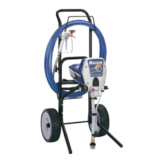
Operation
Airless Sprayers
- For portable spray applications of architectural paints and coatings -
US Patent 6,752,067
European Patent 1 208 287
Korean Patent 10-0668583
Use water based or mineral spirit-type material only.
Do not use materials having flash points lower than
70°F (21°C). For more information about your mate-
rial request MSDS from distributor or retailer.
ti4309a
Graco Inc. P.O. Box 1441 Minneapolis, MN 55440-1441
Copyright 2004, Graco Inc. is registered to I.S. EN ISO 9001
(Specifications, page 2.)
M
dx
AGNUM
Model 232735
Model 247328
M
XR7
AGNUM
Model 232745
Visit our website;
http://Magnum.Graco.com
309225W
IMPORTANT SAFETY INSTRUCTIONS.
Read all warnings and instructions in this
manual. Save these instructions. See page
2 for model and series information including
dispense rate, recommended hose length,
guns, and maximum working pressure.
Model 232740
M
XR5
AGNUM
M
XR9
AGNUM
Model 232750
Advertisement
Table of Contents

Related Manuals for Graco MAGNUM 309225W


Summary of Contents for Graco MAGNUM 309225W
- Page 1 Operation Airless Sprayers - For portable spray applications of architectural paints and coatings - US Patent 6,752,067 European Patent 1 208 287 Korean Patent 10-0668583 Use water based or mineral spirit-type material only. Do not use materials having flash points lower than 70°F (21°C).
-
Page 2: Specifications
Models Models Model Name, Model No. Series Magnum dx 232735 Magnum dx 247328 – Magnum XR5 232740 Magnum XR7 232745 Magnum XR9 232750 Specifications This equipment is not intended for use with flammable or combustible materials used in places such as cabinet shops or other “factory”, or fixed locations. If you intend to use this equipment in this type of application, you must comply with NFPA 33 and OSHA requirements for the use of flammable and combustible materials. - Page 3 Warnings The following are general warnings related to the setup, use, grounding, maintenance and repair of this equipment. Additional, more specific warnings may be found throughout the body of this manual where applicable. Symbols appearing in the body of the manual refer to these general warnings.
- Page 4 Warnings EQUIPMENT MISUSE HAZARD Misuse can cause death or serious injury. • Do not exceed the maximum working pressure or temperature rating of the lowest rated system component. Read Technical Data in all equipment manuals. • Use fluids and solvents that are compatible with equipment wetted parts. Read Technical Data in all equipment manuals.
-
Page 5: Thermal Overload
Installation Grounding and Electric Requirements Sprayer must be grounded. Grounding reduces the risk of static and electric shock by providing an escape wire for electrical current due to static build up or in the event of a short circuit. The 120 Vac spray- ers require a 120 Vac, 60 Hz, 15A cir- cuit with a ground-... -
Page 6: Component Identification
Component Identification Component Identification Electric motor (inside enclosures) Power switch Pressure control knob Pump fluid outlet fitting ™ InstaClean fluid filter (XR models only) ™ Power-Piston pump (behind Easy Access door) (XR models only) Suction tube Prime tube (with diffuser) Spray- Prime/Drain valve control Fluid inlet connection/ inlet valve Inlet screen... -
Page 7: Spray Guns
Component Identification Sprayers Magnum XR7 Connect cart handle on XR7 and XR9 as fol- lows: 1. Position handle on frame and align bolt holes in frame. 2. Run bolts through holes with heads pointing toward each other and hand tighten wingnuts. NOTE: For space-saving configuration, loose, (but do not remove) wing- nuts. -
Page 8: Operation
Operation Operation Pressure Relief Procedure Follow Pressure Relief Procedure when you stop spraying and before cleaning, checking, servicing, or transporting equipment. Read Injection Warning, page 3. 1. Turn power switch (B) OFF and unplug power cord. 2. Turn Spray-Prime/Drain valve (J) to PRIME to relieve pressure. - Page 9 Setup 1. Unscrew tip and guard assembly from gun. 2. Uncoil hose and con- nect one end to gun. 3. Connect other end of hose to sprayer. XR models dx models connect here If hose is already connected, make sure connections are tight.
-
Page 10: Oil- Or Water-Based Materials
Priming Priming Oil- or Water-based Materials To spray lacquers, purchase Lacquer Conversion Kit 248202, and follow Prim- ing procedure for oil-based materials. To spray water-based materials after spraying oil-based materials, flush the system thoroughly with water first. The water flowing out of prime tube should be clear and solvent-free before you begin spraying the water-based material. -
Page 11: Pump Check Valves
11. Submerge suction tube in paint. 12. Turn power switch ON. 13. When paint starts to come out of prime tube, aim gun toward waste pail, pull and hold gun trigger and turn Spray-Prime/Drain valve to SPRAY. Motor stopping indicates pump and hose are primed with paint. -
Page 12: Unclogging Spray Tip
Installing Tip and Base Installing Tip and Base 1. Engage trigger lock. 2. Verify tip and guard parts are assembled in order shown. retaining nut metal seat guard Use tip to align seat Tip must be pushed all the way into guard in guard. -
Page 13: Tip Selection
Tip Selection Selecting Tip Hole Size Tips come in a variety of hole sizes for spray- ing a range of fluids. Your sprayer includes an 0.015 in (0.38 mm) tip for use in most spraying applications. Use the following table to deter- mine the range of recommended tip hole sizes for each fluid type. -
Page 14: Reversible Tip Selection Chart
Tip Selection Reversible Tip Selection Chart Fan Width 12 in. Tip Part (305 mm) from surface 221311 6 - 8 in. (152 - 203 mm) 221411 8 - 10 in. (203 - 254 mm) 221313 6 - 8 in. (152 - 203 mm) 221413 8 - 10 in. -
Page 15: Spraying Techniques
Spraying Techniques This sprayer is set up for most airless spraying applications. Details on tip selection, tip wear, coat thickness, etc. are provided on page 13. Motor only runs when gun is triggered. Sprayer is designed to stop pumping when gun trigger is released. -
Page 16: Shutdown And Cleaning
Shutdown and Cleaning Triggering Gun Pull trigger after starting stroke. Release trig- ger before end of stroke. Gun must be moving when trigger is pulled and released. Shutdown and Cleaning If spraying lacquers, purchase Lacquer Conversion Kit 248202. Follow Shutdown and Cleaning procedures for oil-based materials. -
Page 17: Power Flush
7. Turn power switch ON. 8. Slowly align arrow on sprayer with Pail symbol on Pressure Control knob until pump starts. 9. Flush until approximately 1/3 of the flushing fluid is emptied from the pail. 10. Turn power switch OFF. Turn Spray-Prime/Drain valve to SPRAY. - Page 18 Shutdown and Cleaning 9. Turn lever to close power flush attachment. 10. Unscrew inlet screen from suction tube. Place inlet screen in waste pail. 11. Connect garden hose to suction tube with Power Flush attach- ment. Leave prime tube in waste pail.
-
Page 19: Cleaning Instaclean ™ Fluid Filter
Cleaning InstaClean Fluid Filter (XR models only) The InstaClean Fluid Filter prevents particles from entering paint hose. After each use, remove and clean it to insure peak perfor- mance. 1. Turn power switch OFF. 2. Disconnect airless spray InstaClean filter hose from sprayer and remove... -
Page 20: Short-Term Storage
Storage Storage Short Term Storage 2 days) 1. Place suction and drain tube in paint can. 2. Cover can and hoses tightly with plastic wrap. a. Engage trigger lock. b. Leave gun attached to hose. c. Remove tip and guard and clean with water or flushing solvent. -
Page 21: Stowing Sprayer
5. Turn pressure control knob clockwise until the pump turns on. 6. When storage fluid comes out of prime tube (5-10 seconds) turn power switch OFF. 7. Turn Spray-Prime/Drain valve to SPRAY to keep storage fluid in sprayer dur- ing storage. Stowing Sprayer CAUTION •... -
Page 22: Troubleshooting
Troubleshooting Troubleshooting Check everything in this Troubleshooting Table before you bring the sprayer to a Graco/Magnum authorized service center. Refer to Component Identification, page 6 for reference letters used in table. Problem Power switch is on and sprayer is plugged in, but motor does not run, and pump does not cycle. - Page 23 Problem Pump does not prime. Pump does not prime. Spray gun stopped spraying. Pump cycles but does not build up pressure. Pump cycles but does not build up pressure. Pump cycles but does not build up pressure. 309225W Cause Spray-Prime/Drain Valve (J) is in SPRAY position.
- Page 24 Troubleshooting Problem Pump cycles, but paint only dribbles or spurts when spray gun is trig- gered. Spray pattern is inconsistent or is leaving stripes. Pressure is set at maximum but cannot achieve a good spray pattern. Pressure is set at maximum but cannot achieve a good spray pattern.
- Page 25 Problem Motor is hot and runs intermittently. This is NOT a thermal overload con- dition. Motor automatically shuts off due to excessive heat. Damage can occur if cause is not corrected. Thermal Overload, page 5. Building circuit breaker opens after sprayer operates for 5 to 10 minutes.
-
Page 26: Maintenance And Service
Maintenance and Service Maintenance and Service CAUTION Protect the internal drive parts of this sprayer from water. Openings in shroud allow cooling of mechanical parts and elec- tronics inside. If water gets into these open- ings, the sprayer could malfunction or be permanently damaged. -
Page 27: Technical Data
Technical Data AGNUM Working pressure 0-2800 psi (0-19 MPa, range 0 -193 bar) Electric motor All 120 Vac: 6.5A Model 247238: 3.5A (open frame, universal) Operating horsepower Maximum delivery 0.24 gpm (0.91 lpm) (with tip) Paint hose 3/16 in. x 25 ft (4.8 mm x 8 m) Maximum tip hole size 0.015 in. -
Page 28: Graco Standard Warranty
Graco Standard Warranty Graco Standard Warranty Graco warrants all equipment referenced in this document which is manufactured by Graco and bearing its name to be free from defects in material and workmanship on the date of sale to the original purchaser for use. With the exception of any special, extended, or limited warranty published by Graco, Graco will, for a period of twelve months from the date of sale, repair or replace any part of the equipment determined by Graco to be defective.