Table of Contents
Advertisement
Repair
™
390
Airless Sprayer
- For portable spray applications of architectural paints and coatings -
3300 psi (22.7MPa, 227bar) Maximum Working Pressure
IMPORTANT SAFETY INSTRUCTIONS!
Read all warnings and instructions. Save these instructions. Contact Graco Customer Service
or your local Graco distributor to obtain a manual in your language.
Stand
ProStep
Model*
262019, 253958
254968, 254969, 256391
254998, 262024, 256392
256481, 253961
*all models not available in all countries
Graco Inc., PO Box 1441, Minneapolis, MN 55440-1441
Copyright 2004, Graco Inc. is registered to I.S. EN ISO 9001
ti11608a
Hi-Boy
ti11583a
VAC
120
North America
240
Europe / Europe
240
Asia / Australia
110
Country
✔
multicord
✔
UK
310824D
Related Manuals
310820
309639
309250
310876
ti11626a
✔
✔
Advertisement
Table of Contents

Related Manuals for Graco 256391


Summary of Contents for Graco 256391
- Page 1 Stand ProStep Model* 262019, 253958 254968, 254969, 256391 254998, 262024, 256392 256481, 253961 *all models not available in all countries Graco Inc., PO Box 1441, Minneapolis, MN 55440-1441 Copyright 2004, Graco Inc. is registered to I.S. EN ISO 9001...
-
Page 2: Table Of Contents
Contents Manual Conventions ......2 Warnings ....... . . 3 Component Identification . -
Page 3: Warnings
Warning The following warnings are for the setup, use, grounding, maintenance and repair of this equipment. The exclamation point symbol alerts you to a general warning and the hazard symbol refers to procedure-specific risks. Refer back to these warnings. Additional, product-specific warnings may be found throughout the body of this manual where appli- cable. - Page 4 All parts of the spray system, including the pump, hose assembly, spray gun, and objects in and around the spray area shall be properly grounded to protect against static discharge and sparks. Use Graco conductive or grounded high-pressure airless paint sprayer hoses.
- Page 5 EQUIPMENT MISUSE HAZARD Misuse can cause death or serious injury. • Always wear appropriate gloves, eye protection, and a respirator or mask when painting. • Do not operate or spray near children. Keep children away from equipment at all times. •...
-
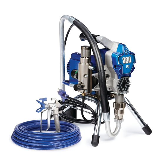
Page 6: Component Identification
Component Identification Item English Pressure Control ON/OFF switch Power Cord Fluid Outlet Prime Valve Pump Suction Hose Drain Hose Fluid Hose Guard Trigger Safety Lock Model/Serial Tag Filter Platform Component Identification ti12008a 310824D... -
Page 7: Installation
Installation Grounding and Electric Requirements WARNING Your system must be grounded. Read warnings, page The sprayer cord includes: a grounding wire with an appropriate grounding contact. The sprayer requires: 110-120V Units: 100-130VAC, 50/60 Hz, 11A, 1 phase, circuit with a grounding receptacle. 240V Units: 210-255 VAC, 50/60 Hz, 7.5A, 1 phase, cir- cuit with a grounding receptacle. -
Page 8: Pressure Relief Procedure
Pressure Relief Procedure WARNING Follow this Pressure Relief Procedure whenever you are instructed to relieve pressure, stop spraying, check or service equipment or install or clean spray tip. Read Injection Hazard Warning, page 3. 1. Turn OFF power and turn pressure control to lowest pressure setting. -
Page 9: General Repair Information
General Repair Information WARNING Read Electric Shock Warning, page 3 and Burn Hazard Warning, page 4. WARNING Flammable materials spilled on hot, bare, motor could cause fire or explosion. To reduce risk of burns, fire or explosion, do not operate sprayer with cover removed. •... -
Page 10: Troubleshooting
Troubleshooting WARNING Read Electric Shock Warning, page 3, Burn Hazard Warning, page 4 and Pressure Relief Procedure, page 8. Problem (If check is OK, go to next check) Motor Won’t Operate Basic Fluid Pressure 1. Pressure control knob setting. 2. Spray tip or fluid filter may be Basic Mechanical 1. - Page 11 Problem (If check is OK, go to next check) Basic Electrical 1. Electric supply. Meter must read See wiring diagram, page 2. Extension cord. Check extension 3. Sprayer power supply cord. 4. Fuse. Check replaceable fuse on 5. Motor leads are securely fas- 6.
- Page 12 Problem (If check is OK, go to next check) Low Output 1. Worn spray tip. 2. Verify pump does not continue to 3. Prime valve leaking. 4. Suction hose connections. 5. Electric supply with volt meter. 6. Extension cord size and length. 8.
- Page 13 Problem (If check is OK, go to next check) Motor runs and pump 1. Prime Valve Open. strokes 2. Paint supply. 3. Intake strainer clogged. 4. Suction hose leaking air. 5. Intake valve ball and piston ball 6. Leaking around throat packing 7.
-
Page 14: Displacement Pump Replacement
Displacement Pump Replacement See manual 309250 for pump repair instructions. Removal WARNING Read Injection Hazard Warning, page 3, Moving Parts Hazard Warning, page 4 and Pressure Relief Procedure, page 8. 1. Relieve pressure, page 8. 2. Loosen two screws (30) and rotate cover (44). ti6104a 3. - Page 15 Installation WARNING If pump pin works loose, parts could break off due to force of pumping action. Parts could project through air and result in serious injury or property damage. CAUTION If the pump jam nut loosens during operation, the threads of the drive housing will be damaged.
-
Page 16: Drive Housing Replacement
Drive Housing Replacement WARNING Read Injection Hazard Warning, page 3 and page 8. Removal 1. Relieve pressure, page 8. 2. Remove pump (9). Displacement Pump Replace- ment, page 14. Disconnect power cord from outlet. ti5641a 3. Remove two screws (30) and cover (32). 4. -
Page 17: Spin Test
Spin Test See Wiring Diagram, page 28. WARNING Read Electric Shock Warning, page 3 and Pressure Relief Procedure, page 8. To check armature, motor winding and brush electrical continuity: 1. Relieve pressure, page 8. Disconnect power cord from outlet. 2. Remove two screws (30) and shroud (29). 3. -
Page 18: Fan Replacement
Fan Replacement Removal WARNING Read Electric Shock Warning, page 3 and Pressure Relief Procedure, page 8. 1. Relieve pressure, page 8. Disconnect power cord from outlet. 2. Remove two screws (30) and shroud (29). 3. Remove spring clip (101) on back of motor. 4. -
Page 19: Motor Brush Replacement
Motor Brush Replacement See Wiring Diagram, page 28. Removal Replace brushes worn to less than 1/4 in. (6mm). Brushes wear differently on each side of motor, check both sides. WARNING Read Electric Shock Warning, page 3 and Pressure Relief Procedure, page 8. 1. -
Page 20: Control Board Replacement
Control Board Replacement See Wiring Diagram, page 28. WARNING Read Electric Shock Warning, page 3 and Pressure Relief Procedure, page 8. Removal 1. Relieve pressure, page 8. Disconnect power cord from outlet. 2. Remove two screws (30) and shroud (29). 3. - Page 21 Installation 1. Position grommet and power cord wires through strain relief in control board (33). ti6122a 2. Reconnect the power cord connectors to the correct terminals indicated on the control board (120V, black and white, 240V, blue and brown) on control board (33).
-
Page 22: Fuse Replacement
Fuse Replacement Removal 1. Relieve pressure, page 8. Disconnect power cord from outlet. 2. Remove two screws (30) and shroud (29). 3. Remove fuse from control board. 4. Remove spare fuse from motor. Spare Fuse (included n 110V and 120 models only) Installation 1. -
Page 23: Pressure Control Assembly Replacement
Pressure Control Assembly Replacement See Wiring Diagram, page 28. WARNING Read Electric Shock Warning, page 3 and Pressure Relief Procedure, page 8. Removal 1. Relieve pressure, page 8. Disconnect power cord from outlet. 2. Remove two screws (30) and shroud (29). 3. -
Page 24: Manifold Replacement
Manifold Replacement See Wiring Diagram, page 28. WARNING Read Electric Shock Warning, page 3 and Pressure Relief Procedure, page 8. Removal 1. Relieve pressure, page 8. Disconnect power cord from outlet. 2. Remove drain line (40) and barbed fitting (20) from manifold. - Page 25 Drain Line Replacement This procedure should be used whenever you replace the manifold and reinstall an existing drain line or install a new drain line using the Drain Line Kit. Removal To remove the drain line (40) from the manifold: 1.
-
Page 26: Power Cord Replacement
Power Cord Replacement See Wiring Diagram, page 28. WARNING Read Electric Shock Warning, page 3 and Pressure Relief Procedure, page 8. Removal 1. Follow Control Board Replacement removal instructions, steps 1-8, page 20. 2. Disconnect green ground wire (G) from sprayer by loosening grounding screw (31). -
Page 27: Motor Replacement
Motor Replacement See Wiring Diagram, page 28. WARNING Read Electric Shock Warning, page 3 and Pressure Relief Procedure, page 8. CAUTION Do not drop gear cluster (3) and (2) when removing drive housing (5). Gear cluster may stay engaged in motor frontend bell or drive housing. -
Page 28: Wiring Diagram
Wiring Diagram 120V Model Pressure Control Assembly 240V Model Capacitor from Motor 2 x Yellow ti5643a Power White Plug from Motor Red (+) 2 x Yellow Black (-) ti5857a Brown Power Plug Wiring Diagram Red (+) Black (-) Replaceable Fuse ON/OFF Switch Black... -
Page 29: Technical Data
Technical Data Power requirements ......100/120V AC, 50/60 hz, 11A, 1 phase Generator required . -
Page 30: Graco Standard Warranty
Graco Standard Warranty Graco warrants all equipment referenced in this document which is manufactured by Graco and bearing its name to be free from defects in material and workmanship on the date of sale to the original purchaser for use. With the exception of any special, extended, or limited warranty published by Graco, Graco will, for a period of twelve months from the date of sale, repair or replace any part of the equipment determined by Graco to be defective.