Table of Contents
Advertisement
Quick Links
Advertisement
Table of Contents
Troubleshooting

Related Manuals for Zeiss Axiovert 40


Summary of Contents for Zeiss Axiovert 40
- Page 4 Violations will entail an obligation to pay compensation. The manual is not covered by an update service. Issued by: Carl Zeiss Light Microscopy P.O.B. 4041 D-37030 Göttingen...
- Page 5 CONTENTS DESCRIPTION...
- Page 6 OPERATION...
- Page 7 MAINTENANCE AND TROUBLESHOOTING ANNEX...
- Page 8 LIST OF ILLUSTRATIONS...
- Page 10 NOTE • • •...
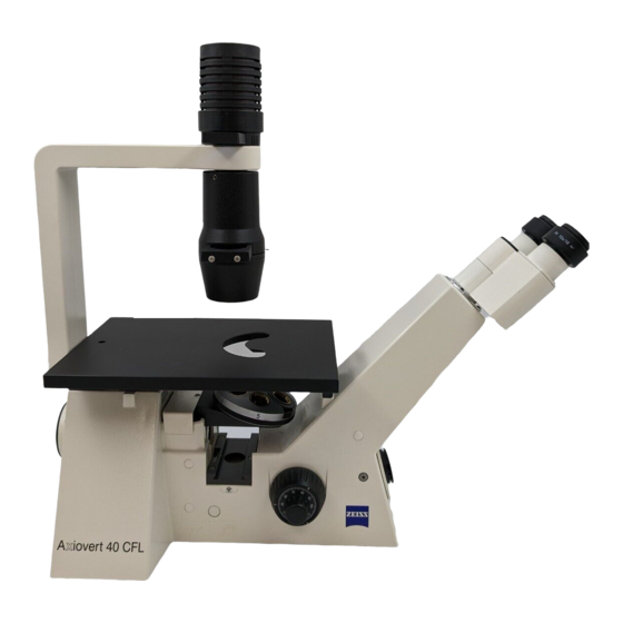
- Page 11 GENERAL VIEW Axiovert 40 CFL...
- Page 13 NOTES ON INSTRUMENT SAFETY NOTE This symbol is a warning, which you must observe under all circumstances. CAUTION This symbol is a warning, which indicates a hazard to the instrument or instrument system. CAUTION This symbol is a warning, which indicates a hazard to the user of the instrument. CAUTION Hot surface! CAUTION...
- Page 14 ± ...
- Page 17 Description Name and intended use Laboratory microscopes Research microscopes • • Instrument description Axiovert 40 C Axiovert 40 CFL...
- Page 18 • • • • • • • • • • • • • • • • • •...
- Page 19 1.2.1 Mechanical design Axiovert 40 C stand • • • • • • • • Axiovert 40 CFL stand • • • Fig. 1 1 Instrument models...
- Page 20 1.2.2 Optical design Fig. 1 2 Optical diagram of Axiovert 40...
- Page 21 Technical data (1) Dimensions and weight (2) Ambient conditions ° ° ° (3) Operating data...
- Page 22 ± (4) Light sources (5) Optical/mechanical data...
- Page 23 ³ ³ °...
- Page 24 System overview Fig. 1 3/1 Axiovert 40 system overview...
- Page 25 Fig. 1-3/2 Axiovert 40 system overview...
- Page 26 Fig. 1-3/3 Axiovert 40 system overview...
- Page 27 Operation Installation of the microscope 2.1.1 Unpacking • • • • • • • Fig. 2 1 Axiovert 40 packing units...
- Page 28 2.1.2 Installation (1) Preparations • • • • NOTE Fig. 2 2 Unpacking and installation (2) Screwing in of objectives • Fig. 2 3 Screwing in objectives...
- Page 29 (3) Inserting diaphragm sliders • NOTE Fig. 2 4 Inserting diaphragm sliders (4) Mounting the HBO 50 illuminator • • • Fig. 2 5 Mounting the HBO 50 illuminator...
- Page 30 (5) Mounting the attachable object traverser M • NOTE • Fig. 2 6 Attaching the attachable object traverser M NOTE •...
- Page 31 (6) Connection to the power outlet CAUTION • • NOTE • • … CAUTION Fig. 2 7 Connection to the power outlet...
- Page 32 (7) Inserting the eyepieces • NOTE Fig. 2 8 Inserting the eyepieces (8) Compensation for defective vision 1) With one fixed and one focusing eyepiece • 2) With two focusing eyepieces • • • NOTE...
- Page 33 (9) Using the binocular tube • • (10) Inserting an eyepiece reticle (26 mm dia.) Fig. 2 9 Positions of the binocular tube • • • • • Fig. 2 10 Inserting an eyepiece reticle...
- Page 34 (11) Switching on/setting the instrument • • • • • Fig. 2 11 Switching on/setting the instrument NOTE Start-up...
- Page 35 Use of LD objectives Fig. 2 12 Working with LD objectives Table of free working distances (FWD) on Axiovert 40 Objective Name Catalogue No. with coverglass cap without coverglass cap (000000-1016-757) for bot for bottom thickness tom thickness 0.17 - 0.6...
- Page 36 Use of objectives with correction mount (corr objectives) CAUTION Use of immersion objectives CAUTION...
- Page 37 Illumination and contrast techniques • • • 2.4.1 Use of condensers • • NOTE • NOTE...
- Page 38 Height adjustment of the condenser 0.55 Á • • Fig. 2 13 Condenser 0.55 2.4.2 Brightfield illumination • • • • NOTE • Fig. 2 14 Various modes of brightfield illumination...
- Page 39 2.4.3 Phase contrast • NOTE • • • • Fig. 2 15 Observation in phase contrast Fig. 2 16 Illustration of phase-contrast adjustment • •...
- Page 40 NOTE • • • Fig. 2 17 Inserting the annular diaphragms Objective Annular diaphragms for condenser 0.55 condenser 0.4 condenser 0.2 •...
- Page 41 2.4.4 VAREL • • • • • • NOTE Fig. 2 18 Observation with VAREL ° Fig. 2 19 VAREL with microtiter plates NOTE • •...
- Page 42 • • Objective VAREL Oblique brightfield Unilateral darkfield illumination illumination phase ring VAREL ring VAREL diaphragm Fig. 2 20 Pupil images with VAREL Preparing the slider Var, H, Var for phase contrast • • • Fig. 2 21 Slider Var, H, Var Objective VAREL diaphragms for condenser 0.55...
- Page 43 2.4.5 PlasDIC • • • • • • Fig. 2 22 Observation with PlasDIC...
- Page 44 • • • • NOTE Preparing the slider Ph, H, PlasDIC • • • NOTE Fig. 2 23 Slider Ph, H, PlasDIC...
- Page 45 2.4.6 Incident-light fluorescence • • • • • • Fig. 2 24 Observation in incident-light fluorescence...
- Page 46 Working with attachable object traverser M and mounting frames • • • Fig. 2 25 Working with attachable object traverser M ∅ • • • • • • • •...
- Page 47 Counting, measuring and framing reticles Crossline micrometer 14:140, d=26 Net micrometer 25/2x2, d = 26 mm ≤ Net micrometer 12.5x12.5/5;10 / d = 26 mm Framing reticle MC 2.5x / d = 26 mm Stage micrometer, positive, 5+100/100y d = 0.17 mm "...
- Page 48 Working with micromanipulators • • • Fig. 2 27 Mounting facilities for micromanipulators...
- Page 49 Replacing the specimen stage • • • Fig. 2 28 Replacing the specimen stage...
- Page 50 2.8.1 Specimen stage glass Installation • • • Fig. 2 29 Mounting the specimen stage glass 2.8.2 Heatable stage and temperable microscope stage • • • •...
- Page 51 Documentation Mounting compact digital cameras • • • • • Fig. 2 30 Camera system...
- Page 52 • • • Notes on the adjustment of the digital camera adapter D 40 M37/52x0.75 and the camera settings • • ∞ • • • Fig. 2 31 Adjusting the digital camera adapter • • • • •...
- Page 53 Maintenance and troubleshooting Maintenance • • • • ° • • • • NOTE • ° ° • •...
- Page 54 Troubleshooting and service • • (1) Checking the line voltage • • Fig. 3 1 Checking the line voltage...
- Page 55 (2) Replacing the halogen bulb CAUTION Make sure to let them cool down sufficiently! • • • • • CAUTION before • Fig. 3 2 Replacing the halogen bulb...
- Page 56 (3) Replacing the HBO 50 • • • • Wavelength in nm Fig. 3 3 HBO 50 illuminator with line spectrum...
- Page 57 Safety notes for the use of the HBO 50 CAUTION • • • CAUTION Caution: Hot surface! Replacing the HBO 50 lamp CAUTION • • • • • Fig. 3 4 Replacing the lamp of the HBO 50...
- Page 58 • CAUTION • • • • • CAUTION • • •...
- Page 59 Adjustment of the HBO 50 CAUTION • • • • Fig. 3 5 Adjustment of HBO 50 • • • Fig. 3 6 Lamp image...
- Page 60 (4) Replacing reflector modules FL P&C on 3-position reflector slider P&C • • • • • Fig. 3 7 Replacing the reflector modules FL P&C...
- Page 61 (5) Changing the filter set CAUTION • • • • Fig. 3 8 Changing the fluorescence filter set Fig. 3 9 Inserting filters and dichroic beam splitter...
- Page 62 • • (6) Changing the dichroic beam splitter CAUTION Fig. 3 10 Changing the dichroic beam splitter • • emission excitation • excitation emis sion • • Fig. 3 11 Mounting the dichroic beam splitter...
- Page 63 NOTE • excitation emis sion • • Fig. 3 12 Marking of dichroic beam splitter •...
- Page 64 (7) Service authorized...
- Page 65 ANNEX • •...
- Page 67 Index...
- Page 71 List of abbreviations...