Table of Contents
Advertisement
Advertisement
Chapters
Table of Contents
Troubleshooting

Related Manuals for Zeiss Axiovert 200


Summary of Contents for Zeiss Axiovert 200
- Page 1 Operating Manual Axiovert 200 / Axiovert 200 M Inverted Microscopes...
- Page 2 INTRODUCTION Carl Zeiss Copyright Axiovert 200 Knowledge of this manual is required for the operation of the instrument. Would you please therefore make yourself familiar with the contents of this manual and pay special attention to hints concerning the safe operation of the instrument.
-
Page 3: Table Of Contents
Notes on instrument safety..................0-7 Notes on warranty ....................0-10 Overall view of the Axiovert 200................0-11 Overall view of the Axiovert 200 M................0-11 Microscopy in transmitted-light brightfield in a few steps ........... 0-12 CHAPTER 1 INSTRUMENT DESCRIPTION ..................1-3 Name and intended application ...................1-3... - Page 4 2.7.4 Changing the beam splitter in the FL reflector module ..........2-16 Connection to the line ....................2-18 Interfaces of the Axiovert 200 M ................2-19 2.10 Switch microscope and ebq 100 dc power supply on and off........2-19 2.11 Equipotential bonding terminals ................
- Page 5 Axiovert 200 M (motorized)..................3-16 3.2.1 Operation and function controls on the Axiovert 200 (motorized)....... 3-16 3.2.2 Switching on and basic settings on the Axiovert 200 M (motorized) ......3-23 Illumination and contrasting techniques..............3-28 3.3.1 Setting of transmitted-light brightfield for KÖHLER illumination........3-28 3.3.2...
- Page 6 INTRODUCTION Carl Zeiss Contents Axiovert 200 page CHAPTER 4 CARE, MAINTENANCE, TROUBLESHOOTING AND SERVICE........4-3 Care ........................... 4-3 Maintenance ......................4-4 4.2.1 Performing checks ...................... 4-4 4.2.2 Changing the fuses on the microscope................ 4-4 4.2.3 Changing the fuses on the ebq 100 dc power supply ..........4-5 Service........................
-
Page 7: Notes On Instrument Safety
Carl Zeiss Notes on instrument safety The Axiovert 200 / Axiovert 200 M microscopes were designed, produced and tested in compliance with DIN 61010-1 (IEC 1010-1), Safety requirements for electrical measuring, control and laboratory instruments, and meet the requirements of appendix I of directive 73/23/EC and the relevant CSA and UL directives. - Page 8 If it is established that the protection measures are no longer effective, the instrument must be switched off and safeguarded against inadvertent operation. For repair of the instrument, contact the Carl Zeiss microscope service in Germany (see page 4-6) or your local Carl Zeiss agency.
- Page 9 The instruments may only be operated by trained personnel who must be aware of the possible danger involved with microscopy and the relevant application. The Axiovert 200 microscopes are opto-mechanical precision instruments which can be impaired in their performance or damaged when handled improperly.
-
Page 10: Notes On Warranty
With the exception of the work specified in this manual, no maintenance or repair of the microscopes may be performed. Repairs may only be performed by Carl Zeiss service staff or specially authorized personnel. Should any defect occur with the instrument, please get in touch with the Carl Zeiss microscopy service in Germany (see page 4-6) or your local Zeiss agency. -
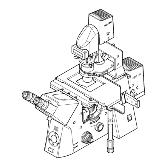
Page 11: Overall View Of The Axiovert 200
INTRODUCTION Axiovert 200 Overall view of the Axiovert 200 and Axiovert 200 M Carl Zeiss B 40-080 e 03/01 0-11... -
Page 12: Microscopy In Transmitted-Light Brightfield In A Few Steps
Axiovert 200 Microscopy in transmitted-light brightfield in a few steps Before starting to use the Axiovert 200, make sure to read the notes on instrument safety and the chapters entitled "Instrument Description" (Chapter 1) and "Start-up" (Chapter 2). Make the microscope ready for operation as described in chapter 2 and switch it on via the On/Off switch (0-2/1). - Page 13 INTRODUCTION Axiovert 200 Microscopy in transmitted-light brightfield in a few steps Carl Zeiss 1 On / Off switch 10 Turning or sliding knob for 18 Centering screw for condenser 2 Objective nosepiece Bertrand lens and manual shutter 19 Turret disk of condenser...
- Page 14 INTRODUCTION Carl Zeiss Microscopy in transmitted-light brightfield in a few steps Axiovert 200 0-14 B 40-080 e 03/01...
- Page 15 INSTRUMENT DESCRIPTION Axiovert 200 Contents / List of illustrations Carl Zeiss INSTRUMENT DESCRIPTION Contents INSTRUMENT DESCRIPTION ..................1-3 Name and intended application..................1-3 Instrument description and main features.................1-5 Microscope configurations and modules................1-6 Objectives........................1-10 Eyepieces........................1-12 Condensers ........................1-12 Specimen stages and mounting frames ................1-13 Binocular tubes......................
- Page 16 INSTRUMENT DESCRIPTION Carl Zeiss Contents / List of illustrations Axiovert 200 B 40-080 e 03/01...
-
Page 17: Chapter 1 Instrument Description
VAREL contrast, and the epi-fluorescence technique. The microscopes Axiovert 200 and Axiovert 200 M are the basis for scientific microscopic work on living cells. The sturdy stand provides attachment possibilities for various tools (micromanipulation), different light sources, temperature control devices, etc. - Page 18 INSTRUMENT DESCRIPTION Carl Zeiss Name and intended application Axiovert 200 Typical fields of application: Observation of intracellular processes in living cell cultures, cell/cell interactions, motility, growth, measurements of potential, drug detection, microinjection, IVF (in-vitro fertilization), toxicity examinations, patch-clamp technique, ion measurements, digital recording, long-time / time lapse...
-
Page 19: Instrument Description And Main Features
Carl Zeiss Instrument description and main features The Axiovert 200 / Axiovert 200 M is available either as manual or as motorized version. The accessory components are part of a modular system. For documentation purposes, the Axiovert 200 / Axiovert 200 M can be equipped with the maximum of five camera / TV ports in accordance with the customer's requests. -
Page 20: Microscope Configurations And Modules
INSTRUMENT DESCRIPTION Carl Zeiss Microscope configurations and modules Axiovert 200 Microscope configurations and modules Fig. 1-1 Microscope configurations and modules (sheet 1) B 40-080 e 03/01... - Page 21 INSTRUMENT DESCRIPTION Axiovert 200 Microscope configurations and modules Carl Zeiss Fig. 1-2 Microscope configurations and modules (sheet 2) B 40-080 e 03/01...
- Page 22 INSTRUMENT DESCRIPTION Carl Zeiss Microscope configurations and modules Axiovert 200 Fig. 1-3 Microscope configurations and modules (sheet 3) B 40-080 e 03/01...
-
Page 23: Microscope Configurations And Modules
INSTRUMENT DESCRIPTION Axiovert 200 Microscope configurations and modules Carl Zeiss Fig. 1-4 Microscope configurations and modules (sheet 4) B 40-080 e 03/01... -
Page 24: Objectives
The objectives are the optical centerpiece of the microscope. The following is an example of how objectives can be labelled: A-Plan 10 /0.20 HD /- Key: objective magnification, with a color ring on the objective being allocated to each magnification step (Zeiss color code) 0.20 numerical aperture reflected-light brightfield and darkfield objective infinite tube length can be used without cover slip (D = 0 mm) or with cover slip thickness D = 0.17 mm... -
Page 25: Objectives
INSTRUMENT DESCRIPTION Axiovert 200 Objectives Carl Zeiss The following objectives are available for the Axiovert 200 / Axiovert 200 M microscope: Objective type Magnification/ Cover slip Free working Contrasting Cat. No. numeric aperture thickness D in distance A in A-Plan A-Plan 5x/0.12... -
Page 26: Eyepieces
INSTRUMENT DESCRIPTION Carl Zeiss Eyepieces / Condensers Axiovert 200 Eyepieces The following eyepieces are available for the Axiovert 200 and Axiovert 200 M: Eyepiece type Image angle Cat. No. 24.7° 455043-0000-000 Eyepiece W-PL 10 /23 Br. foc. 24.7° 000000-1016-758 Eyepiece W-PL 10 /23 Br. foc. -
Page 27: Specimen Stages And Mounting Frames
Axiovert 200 Specimen stages and mounting frames / Binocular tubes Carl Zeiss Specimen stages and mounting frames The Axiovert 200 microscopes can be equipped with the following specimen stages and mounting frames: Description Cat. No. Specimen stage 250x230 mm with ceramic surface and... -
Page 28: Technical Data
Stand Axiovert 200..................approx. 295 707 mm Weight Axiovert 200 without fluorescence equipment ..............approx. 26 kg Axiovert 200 M with fluorescence equipment ..............approx. 40 kg Ambient conditions Storage and transport (in packaging): Permissible ambient temperature................... -40 to +50 °C Operation: Permissible ambient temperature.................. -
Page 29: Technical Data
Line frequency ........................50 to 60 Hz Power consumption with internal power units Axiovert 200 ...........................235 VA Axiovert 200 M ........................235 VA and external power units Power supply N XBO 75, 100 ... 240 V AC ................130 VA Power supply N HBO 100, 90 ... 240 V AC................265 VA... - Page 30 INSTRUMENT DESCRIPTION Carl Zeiss Technical Data Axiovert 200 1-16 B 40-080 e 03/01...
-
Page 31: Start-Up
2.5.5 Attachment of gliding stage Z..................2-12 Attachment of condensers ..................... 2-13 2.6.1 Condensers for the Axiovert 200..................2-13 2.6.2 Condensers from the Axioplan 2 imaging / Axioskop 2 product line ........ 2-13 2.6.3 Changing the DIC prism in the condenser turret ............. 2-14 Reflector turret ...................... - Page 32 START-UP Carl Zeiss Contents Axiovert 200 Connection to the line....................2-18 Interfaces of the Axiovert 200 M ................... 2-19 2.10 Switch microscope and ebq 100 dc power supply on and off ......... 2-19 2.11 Equipotential bonding terminals ..................2-19 2.12 HAL 100 halogen illuminator ..................
- Page 33 Changing the filter set in the FL reflector module ............2-16 Fig. 2-19 Changing the beam splitter.................... 2-16 Fig. 2-20 Changing the beam splitter.................... 2-17 Fig. 2-21 Axiovert 200 M (rear)..................... 2-18 Fig. 2-22 Power supply ebq 100 dc (rear)..................2-18 Fig. 2-23 Axiovert 200 M (rear)..................... 2-19 Fig. 2-24 Power supply ebq 100 dc (front) ..................
- Page 34 START-UP Carl Zeiss List of illustrations Axiovert 200 B 40-080 e 03/01...
-
Page 35: Chapter 2 Start-Up
START-UP On account of the complexity of the equipment and to ensure proper functioning, installation and initial start-up of the Axiovert 200 or Axiovert 200 M at your site will be performed entirely by the responsible Carl Zeiss agency. The following major services will be performed: Installation of the microscope, assembly and alignment of all components (if these are not already factory-aligned). -
Page 36: Attachment Of Binocular (Photo) Tube
Attachment of binocular (photo) tube All the binocular tubes listed in the microscope configuration can be attached to the Axiovert 200 and Axiovert 200 M as described below. Proceed as follows to attach a tube for the first time, or to replace a tube: Loosen hexagonal screw (2-2/2) using the SW3 ball-headed screwdriver. -
Page 37: Inserting The Eyepiece Reticle
START-UP Axiovert 200 Attachment of binocular (photo)tube Carl Zeiss 2.2.2 Inserting the eyepiece reticle The eyepieces W-PL 10x/23 Br. foc. are intended for use with eyepiece reticles. The slight image shift caused by the additional path through the glass is taken into account on... -
Page 38: Attachment Of Transmitted-Light Illumination
Before attachment of the carrier for transmitted-light illumination 30 W (451380-0000-000) to the stand, the control electronics included in the stand must be changed by Zeiss service staff. Remove the HAL 100 and N HBO 103 illuminators from the microscope. -
Page 39: Screw In Objectives
START-UP Axiovert 200 Screw in objectives Carl Zeiss Screw in objectives Remove dust caps (2-7/1) from the respective openings in the nosepiece. Remove objectives (2-7/2) from the case and screw them in the nosepiece (2-7/3), starting with position 1 (see engraved number), in increasing order of magnification factors. -
Page 40: Attachment Of Microscope Stages
START-UP Carl Zeiss Attachment of microscope stages Axiovert 200 Attachment of microscope stages 2.5.1 Attachment of mechanical stage 130x85 R/L and mounting frame for mechanical stage (K) The mechanical stage is mounted to the stand directly above three contact points with the relevant drilled holes. -
Page 41: Attachment Of Specimen Stage 250X230, Object Guide And Mounting Frame For Object Guide (M)
START-UP Axiovert 200 Attachment of microscope stages Carl Zeiss Because of the large travel range of the scanning stage, it may happen that the stage frame collides with the objectives at the end of the stage travel. 2.5.3 Attachment specimen... -
Page 42: Attachment Of Heating Stage
START-UP Carl Zeiss Attachment of microscope stages Axiovert 200 2.5.4 Attachment of heating stage The heating stage is attached to the contact points of the stand using three spacer disks. Remove any available microscope stage and additional mounting components. Place spacer disks (2-12/2) on the three contact points of the stand. -
Page 43: Attachment Of Condensers
Attachment of condensers Carl Zeiss Attachment of condensers 2.6.1 Condensers for the Axiovert 200 Insert condenser (2-13/1) into the condenser carrier on the carrier for transmitted-light illumination with its dovetail pointing upwards. Make sure that the orientation pin of the... -
Page 44: Changing The Dic Prism In The Condenser Turret
START-UP Carl Zeiss Attachment of condensers Axiovert 200 Insert condenser adapter (2-14/1) into the condenser carrier on the carrier for transmitted-light illumination with its dovetail pointing upwards. Make sure that the orientation pin of the condenser is positioned at the front and exactly engages into the guiding groove of the condenser carrier. -
Page 45: Reflector Turret
START-UP Axiovert 200 Reflector turret Carl Zeiss Reflector turret 2.7.1 Attachment of reflector turret The manual reflector turret can be pushed into the stand either from the right or from the left, depending on which side is accessible. motorized reflector turret can only be inserted from the right, with the instrument being switched off. -
Page 46: Changing The Filter Set In The Fl Reflector Module
START-UP Carl Zeiss Reflector turret Axiovert 200 To remove a reflector module no longer required, first pull it out of the upper spring clamps and then from the lower ones. When equipment has been finished, attach the plastic hood again and press it downwards until the holding catches on the right and left engage in the lower part of the reflector turret. - Page 47 START-UP Axiovert 200 Reflector turret Carl Zeiss Hold both halves of the reflector module together, turn them around into the installation position and put them down. Now tilt the upper module half (2-20/1) upwards and lift it out of the holding elements (2-20/5b) of the lower module half.
-
Page 48: Connection To The Line
The microscope is equipped with a wide-area power unit which automatically adapts to the available line voltage. Voltage change is not required. Fig. 2-21 Axiovert 200 M (rear) The N HBO 103 illuminator (for epi-fluorescence) is supplied via a separate power supply. power supply... -
Page 49: Interfaces Of The Axiovert 200 M
Interfaces of the Axiovert 200 M Prior to connecting any components, switch off the microscope. The Axiovert 200 M is connected to a PC via the RS 232 interface (2-23/2). Motorized components of the Axiovert 200 M (e.g. the motorized condenser) are connected via the SB interfaces (2-23/3). -
Page 50: Hal 100 Halogen Illuminator
START-UP Carl Zeiss HAL 100 W halogen illuminator Axiovert 200 2.12 HAL 100 halogen illuminator 2.12.1 Change / attachment of the HAL 100 halogen lamp Switch off the microscope, remove connector (2-27/4) from the 12 V / 100 W socket (2-27/5) and allow the illuminator to cool down for approx. -
Page 51: Coarse Alignment Of Halogen Illuminator
START-UP Axiovert 200 HAL 100 W halogen illuminator Carl Zeiss 2.12.2 Coarse alignment halogen illuminator Loosen the clamping screw (2-27/2) and remove the halogen illuminator from the carrier for transmitted-light illumination. Switch on the microscope. Direct light beam against a projection area (wall) approx. -
Page 52: Fine Alignment Of Halogen Illuminator
START-UP Carl Zeiss HAL 100 W halogen illuminator Axiovert 200 2.12.4 Fine alignment halogen illuminator Fine alignment requires the diffusion disk to be removed: Loosen clamping screw of HAL 100 W (2-28/1) and remove the illuminator from the carrier for transmitted-light illumination. -
Page 53: Illuminator N Hbo 103
START-UP Axiovert 200 Illuminator N HBO 103 Carl Zeiss 2.13 Illuminator N HBO 103 2.13.1 Attachment / change of the HBO 103 W/2 mercury pressure short-arc lamp The illuminator N HBO 103 and the HBO 103 W/2 mercury pressure short-arc lamp are supplied to the customer in separate packaging for safety reasons. - Page 54 START-UP Carl Zeiss Illuminator N HBO 103 Axiovert 200 Use focusing knob (2-30/3) to bring collector to the position at the very front (in the direction of the light). ball-headed screwdriver loosen clamping screw for lamp housing (2-30/2) and carefully remove lamp housing (2-30/1) from the lamp mount (2-31/3) in an upward direction.
-
Page 55: Coarse Alignment Of Illuminator N Hbo 103
START-UP Axiovert 200 Illuminator N HBO 103 Carl Zeiss 2.13.2 Coarse alignment of illuminator N HBO 103 The following settings for adjustment of the N HBO 103 illuminator are performed in two steps: the coarse adjustment and the subsequent fine adjustment using the adjustment aid. -
Page 56: Attachment Of Illuminator N Hbo 103
START-UP Carl Zeiss Illuminator N HBO 103 Axiovert 200 If required, the above settings for coarse adjustment of the N HBO 103 illuminator can be performed repeatedly. During coarse adjustment of the focal spots, adjusting screws (2-32/1 and 2) marked red must not be changed, since they influence the reflector setting in the HBO 103 illuminator. -
Page 57: Fine Adjustment Of Illuminator N Hbo 103 Using The Adjusting Aid
START-UP Axiovert 200 Illuminator N HBO 103 Carl Zeiss 2.13.4 Fine adjustment illuminator N HBO 103 using the adjusting aid Attach illuminator N HBO 103 to the microscope stand, tighten the clamping screw, and switch on the illuminator. Pull out adjusting aid (2-37/7) from the incident-light tube. -
Page 58: Attachment Of Aqua Stop
START-UP Carl Zeiss Attachment of Aqua Stop Axiovert 200 2.14 Attachment of Aqua Stop Aqua Stop can be used to protect the objective and the nosepiece from liquids. Remove the microscope stage. Put collecting trough 2-38/5) onto nosepiece carrier (2-38/2) and screw it on by means of two screws 2-38/1). - Page 59 START-UP Axiovert 200 Attachment of Aqua Stop Carl Zeiss You can fix the drain hose using the provided clips. Fix the hose in such a way, that the drain gutter is not bent in focusing. Attach the microscope stage again.
- Page 60 START-UP Carl Zeiss Attachment of Aqua Stop Axiovert 200 Objective type Magnification / Contrasting Hole size Silicone ring Cat. No. num. aperture size Plan-Neofluar Plan-Neofluar 5x/0.15 440320-0000-000 Plan-Neofluar 5x/0.15 440321-0000-000 Plan-Neofluar 10x/0.30 440330-0000-000 Plan-Neofluar 10x/0.30 440331-0000-000 Plan-Neofluar 16x/0.50 Imm 440530-0000-000 Plan-Neofluar 16x/0.50 Imm...
-
Page 61: Operation
3.2.1 Operation and function controls on the Axiovert 200 (motorized) ........3-16 3.2.2 Switching on and basic settings on the Axiovert 200 M (motorized) ........ 3-23 Illumination and contrasting techniques ................. 3-28 3.3.1 Setting of transmitted-light brightfield for KÖHLER illumination ........3-28 3.3.2... - Page 62 Centering the phase stop on the condenser ..............3-34 Fig. 3-19 Centering of phase stop (bright in condenser) with phase ring (dark in objective).... 3-34 Fig. 3-20 Components for the transmitted-light DIC technique on the Axiovert 200 ...... 3-37 Fig. 3-21 Setting of VAREL contrast....................3-38 Fig. 3-22 VAREL contrast with microtiter plates ................
-
Page 63: Operation
Axiovert 200 Carl Zeiss OPERATION The Axiovert 200 microscopes are offered in a manual version and in a version with motorized functions and components. In the "Operation" chapter, the manual setting and operation functions are explained first, and the motorized (coded) functions are then explained separately, where required. However, many operation functions are entirely identical in both instrument versions. -
Page 64: Axiovert 200 (Manual)
OPERATION Carl Zeiss Axiovert 200 Axiovert 200 Axiovert 200 (manual) 3.1.1 Operation and function controls on the Axiovert 200 (manual) Fig. 3-1 Operation and function controls on the Axiovert 200 (manual) B 40-080 e 03/01... - Page 65 OPERATION Axiovert 200 Axiovert 200 Carl Zeiss Key to Fig. 3-1: 1 On / Off switch 2 Nosepiece 3 Compartment for analyzer slider (can be equipped from the right or left) 4 Drive controls for XY-movement of the mechanical stage 5 Sideport right 6 Setting wheel for Optovar turret (max.
- Page 66 OPERATION Carl Zeiss Axiovert 200 Axiovert 200 On / Off switch (3-1/1) position 0 = instrument switched off position I = instrument switched on, switch lights up Key HAL on/off (3-1/10) Brief pressing switches the halogen illuminator on or off alternately.
- Page 67 OPERATION Axiovert 200 Axiovert 200 Carl Zeiss Nosepiece with objectives (3-1/2) 6-position nosepiece H, DIC (3-2/1) with compartments for DIC slider (3-2/2) in all objective positions. Fast change of objectives through rotation of the nosepiece via the setting ring (3-2/4).
- Page 68 OPERATION Carl Zeiss Axiovert 200 Axiovert 200 Binocular tubes (3-1/13) The binocular tubes offered permit the individual setting of the interpupillary distance and the viewing height within defined limits. Binocular tube 45°/23 with manual shutter vis (3-3) Shutter switched on / off via rotary knob...
- Page 69 OPERATION Axiovert 200 Axiovert 200 Carl Zeiss Binocular component of the tubes (3-1/14) The eyepiece distance is matched to the individual interpupillary distance by swinging the eyepiece tubes symmetrically towards one another (3-5/A and 3-5/B). Two vertical adjustments through rotation of the binocular component around 180°.
- Page 70 OPERATION Carl Zeiss Axiovert 200 Axiovert 200 Condensers (3-1/23) Depending on their type, condensers (3-7/1) are equipped as follows: 5- or 6-position turret for: brightfield: H phase contrast: Ph0, Ph1, Ph2, Ph3 with centerable stops interference contrast: DIC Varel contrast: Var1, Var2 Aperture diaphragm (iris stop).
- Page 71 OPERATION Axiovert 200 Axiovert 200 Carl Zeiss Centering screw for condenser (3-1/18 and 22) Screws for condenser centering attached to both sides of the carrier for transmitted-light illumination / condenser. Lever for luminous-field diaphragm, transmitted light (3-1/20) Lever attached to the carrier for transmitted-light illumination / condenser which opens and closes the transmitted-light luminous-field diaphragm to set KÖHLER illumination...
- Page 72 Axiovert 200 Axiovert 200 Baseport (3-1/34) Port for the connection of documentation equipment below the Axiovert 200. Setting knob for Frontport / Baseport / vis (3-1/32) Selects the beam splitting ratio for Frontport, Baseport and visual observation. 3 switching positions: 100 % vis (free light path);...
- Page 73 OPERATION Axiovert 200 Axiovert 200 Carl Zeiss 5-position reflector turret (3-1/7) Accepts the maximum of 5 reflector modules for epi-fluorescence. Fast change of reflector position by turning the setting ring of the reflector turret. The activated reflector position is marked with a line (3-9/1) on the right of the reflector turret.
-
Page 74: Switching On And Basic Settings On The Axiovert 200 (Manual)
Axiovert 200 Axiovert 200 3.1.2 Switching on and basic settings on the Axiovert 200 (manual) Switch on the microscope with the on/off switch on the right side (3-11/1). The indicator light in the switch lights up. The microscope is ready for operation after a few seconds. - Page 75 3.1.2.2 Light Manager The Light Manager is automatically activated each time the Axiovert 200 is switched on. The Light Manager automatically sets the illumination intensity of the halogen illuminator last saved for each individual objective position. Therefore, the correct brightness is immediately available in almost all cases.
-
Page 76: Axiovert 200 M (Motorized)
OPERATION Carl Zeiss Axiovert 200 M Axiovert 200 Axiovert 200 M (motorized) 3.2.1 Operation and function controls on the Axiovert 200 (motorized) Fig. 3-13 Operation and function controls on the Axiovert 200 M (motorized) 3-16 B 40-080 e 03/01... - Page 77 OPERATION Axiovert 200 Axiovert 200 M Carl Zeiss Key to Fig. 3-13: 1 On / Off switch 2 Nosepiece (motorized) 3 Reflector turret (motorized) 4 OBJECTIVE keys (forward and backward) 5 REFLECTOR keys (forward and backward) 6 Focusing drive coarse / fine (motor-supported)
- Page 78 OPERATION Carl Zeiss Axiovert 200 M Axiovert 200 FOCUS key - Work / Load (3-13/8) Load Brings the nosepiece to the lowest position. Load Position appears in the lower line of the LCD display. The lower LCD line blinks every second as a warning sign.
- Page 79 OPERATION Axiovert 200 Axiovert 200 M Carl Zeiss LCD display (3-13/17) Two-line display with 16 characters each attached to the carrier for transmitted-light illumination / condenser. Display objective position (3-6/1), magnification (3-6/2) and contrasting technique (3-6/3) in the upper line.
- Page 80 OPERATION Carl Zeiss Axiovert 200 M Axiovert 200 Motorized condensers (3-13/16) Motorized condenser, equipped with: 6-position turret for: brightfield: H phase contrast: Ph1, Ph2, Ph3 with centerable stops interference contrast: DIC I, DIC II If a motorized condenser is recognized by the...
- Page 81 OPERATION Axiovert 200 Axiovert 200 M Carl Zeiss LEFT / RIGHT key for the motorized switching of the Sideport turret (3-13/13) Key to switch the beam splitting ratio for Sideport (doc) right, Sideport (doc) left and VIS (visual observation through the binocular).
- Page 82 OPERATION Carl Zeiss Axiovert 200 M Axiovert 200 Motorized 5-position reflector turret (3-13/3) Accepts the maximum of 5 reflector modules for epi-fluorescence. Fast change of reflector position through pressing the key (forward or backward) on the right of the stand (3-13/5).
-
Page 83: Switching On And Basic Settings On The Axiovert 200 M (Motorized)
Axiovert 200 M Carl Zeiss 3.2.2 Switching on and basic settings on the Axiovert 200 M (motorized) Switch on the microscope with the on/off switch on the right side. The indicator light in the switch lights up. Initialization of the instrument follows. - Page 84 OPERATION Carl Zeiss Axiovert 200 M Axiovert 200 Setting of nosepiece equipment Press one of the two OBJECTIVE keys. Change to nosepiece programming is made, and SET Objective is displayed in the upper line of the LCD display. The set nosepiece position, the magnification and the contrasting technique of the objective are displayed in the lower LCD line.
- Page 85 OPERATION Axiovert 200 Axiovert 200 M Carl Zeiss Setting of Z focus factors and parfocality The matching of focus positions (parfocality) and the adaptation of the focus speed (Z-focus factors) to the objective magnification are normally only performed when the microscope is used for the first time or after the change of objectives in the nosepiece.
- Page 86 This limit is an absolute focus position which applies to all nosepiece positions and which is only corrected by the amount of parfocality alignment of the relevant objective. In the factory alignment of the Axiovert 200 M, the focus limit lies above the upper end position switch and is therefore not effective.
- Page 87 3.2.2.3 Light Manager The Light Manager is applied with the Axiovert 200 M (storage of set values) in the same way as with the manual version. However, the functionality of the Light Manager is considerably greater in the Axiovert 200 M on account of the coding / motorization of the major microscope components.
-
Page 88: Illumination And Contrasting Techniques
3.3.1.3, "Transmitted-light brightfield setting according to KÖHLER on the Axiovert 200 (manual)". 3.3.1.2 Transmitted-light brightfield configuration of the Axiovert 200 manual Each manual Axiovert 200 microscope can be configured to permit the transmitted-light brightfield technique. 3-28 B 40-080 e 03/01... - Page 89 Transmitted-light brightfield setting according to KÖHLER on the Axiovert 200 (manual) Put the Axiovert 200 (manual) in operation as described in chapter 2. Switch on the Axiovert 200 (manual). Select the objective with the lowest magnification (e.g. 10x objective with the yellow ring) on the nosepiece (3-16/2) and ensure the correct stop position.
- Page 90 OPERATION Carl Zeiss Illumination and contrasting techniques Axiovert 200 1 On / Off switch 10 Rotary or slider knob for Bertrand 18 Centering screw for condenser 2 Nosepiece lens and manual shutter 19 Turret of condenser 3 Compartment for slider...
- Page 91 OPERATION Axiovert 200 Illumination and contrasting techniques Carl Zeiss Swing out 3-position filter changer (3-16/14). Place a high-contrast specimen on the microscope stage (3-16/21). Match the eyepiece distance (interpupillary distance) to the user's individual interpupillary distance: For this purpose, pull apart or push together the binocular component (3-16/11) of the tube.
- Page 92 Axiovert 200 3.3.1.4 Transmitted-light brightfield configuration of the Axiovert 200 M Each Axiovert 200 M microscope can be configured to permit the transmitted-light brightfield technique. 3.3.1.5 Transmitted-light brightfield setting according to KÖHLER on the Axiovert 200 M Put the Axiovert 200 M in operation as described in chapter 2.
-
Page 93: Setting Of Transmitted-Light Phase Contrast
3.3.2.2 Configuration of the Axiovert 200 (manual) and Axiovert 200 M Phase contrast objectives with phase rings Ph 0, Ph 1, Ph 2 or Ph 3 for different average numeric apertures which can also be used in brightfield without any restriction. - Page 94 Carl Zeiss Illumination and contrasting techniques Axiovert 200 3.3.2.3 Setting of transmitted-light phase contrast on the Axiovert 200 / Axiovert 200 M Swing phase contrast objective, e.g. Ph 1, into the beam path. Switch phase stop with the same description as the phase contrast objective (e.g.
-
Page 95: Setting Of Differential Interference Contrast (Dic) In Transmitted Light
30° (de Sénarmont) 3.3.3.3 Setting of transmitted-light DIC on the Axiovert 200 (manual) and Axiovert 200 M Swing in the suitable DIC objective. Push appropriate DIC slider (3-20/3) into the compartment on the nosepiece. Make sure that the DIC slider engages in the stop position. - Page 96 OPERATION Carl Zeiss Illumination and contrasting techniques Axiovert 200 Transmitted-light DIC with analyzer slider 30° (de SENARMONT) When the analyzer slider 30° is used, the DIC slider must be brought to the center position first. Swing in the polarizer and bring analyzer 30° (3-20/5) in 0°-position (dark position) (polarizer and analyzer are crossed).
- Page 97 Illumination and contrasting techniques Carl Zeiss 1 Polarizer D (fixed, optional: rotary) 2 Condenser 3 DIC slider 4 Analyzer slider, fixed 5 Analyzer slider 30° Fig. 3-20 Components for the transmitted-light DIC technique on the Axiovert 200 B 40-080 e 03/01 3-37...
-
Page 98: Setting Of Varel Contrast In Transmitted Light
(no flush ring positioning!). 3.3.4.2 Configuration of the Axiovert 200 (manual) and Axiovert 200 M Condenser with turret equipped with VAREL stops. Objectives which are suitable for VAREL contrast, e.g. A-Plan Ph1Var1 or LD A-Plan Ph2Var2. - Page 99 OPERATION Axiovert 200 Illumination and contrasting techniques Carl Zeiss The specimen field with the relevant pupil image of the VAREL diaphragm is shown in Fig. 3-22. In the pupil image, the diaphragm appears rotated by 180°. Fig. 3-22 VAREL contrast with microtiter...
-
Page 100: Setting Of Fluorescence Contrast In Reflected Light
If required, re-adjustment must be performed depending on the operation time. 3.3.5.3 Setting of epi-fluorescence on the Axiovert 200 (manual) and Axiovert 200 M The first epi-fluorescence setting is considerably facilitated if the Plan-Neofluar objective 20x/0.50 and a specimen featuring pronounced fluorescence are used. - Page 101 1 N HBO 103 fluorescence illuminator 2 Iris stop slider (aperture diaphragm) 3 Iris stop slider (luminous-field diaphragm) 4 Nosepiece 5 Reflector turret 6 FL on / off key Fig. 3-24 Components for epi-fluorescence on the Axiovert 200 B 40-080 e 03/01 3-41...
- Page 102 OPERATION Carl Zeiss Illumination and contrasting techniques Axiovert 200 Switch on the NHBO 103 fluorescence illuminator (3-24/1) via the power supply and allow it to heat to operating temperature for approx. 15 minutes. Select the FL reflector module in the reflector turret containing the required fluorescence filter combination (depending on the excitation) and switch it on.
-
Page 103: Documentation
Depending on the instrument configuration, the Axiovert 200 (manual) and Axiovert 200 M microscopes can be equipped with up to five documentation ports. Frontport for the connection of a SLR camera, a video or digital camera (e.g. AxioCam from Zeiss) via a special video or camera adapter. - Page 104 OPERATION Carl Zeiss Documentation Axiovert 200 Order No. / Viewed with / Intermediate / Direction of Viewing direction, Description Switch position image / Monitor motion of object schematic 000000-1005-827 Eyepieces (100% vis) Binocular tube 000000-1005-828 100% vis : 0% doc...
-
Page 105: Photomicrography With Slr Camera
3.4.2 Photomicrography with SLR camera The Axiovert 200 (manual) and Axiovert 200 M microscopes permit the beam path to be switched to 100% vis (visual observation through eyepieces and an open position for activation of the Sideport to the right or left), 100% Frontport (port pointing to the front for photomicrography) or 100% Baseport (port pointing downwards). -
Page 106: Photomicrography Using A Digital Camera And Videomicroscopy
2.5 of the camera adapter. 3.4.3 Photomicrography using a digital camera and videomicroscopy The Axiovert 200 and Axiovert 200 M permit the connection of one video camera or one digital camera (e.g. AxioCam digital camera from Zeiss, (3-26/1) to the Frontport via the 0.63/C-mount video adapter (3-26/2). -
Page 107: Care, Maintenance, Troubleshooting And Service
CARE, MAINTENANCE, TROUBLESHOOTING AND SERVICE Axiovert 200 Contents / List of illustrations Carl Zeiss CARE, MAINTENANCE, TROUBLESHOOTING AND SERVICE Contents CARE, MAINTENANCE, TROUBLESHOOTING AND SERVICE......... 4-3 Care..........................4-3 Maintenance ........................4-4 4.2.1 Performing checks ......................4-4 4.2.2 Changing the fuses on the microscope ................4-4 4.2.3... - Page 108 CARE, MAINTENANCE, TROUBLESHOOTING AND SERVICE Carl Zeiss Contents / List of illustrations Axiovert 200 B 40-080 e 03/01...
-
Page 109: Care
Clean the optical surface by moving in circles starting in the middle. Slight pressure should be exerted on the optics during cleaning. When using the Axiovert 200 in humid climatic zones, proceed as follows: Store the microscope in bright, dry and well ventilated rooms with a humidity of less than 65%; store particularly sensitive components and accessories, such as objectives and eyepieces, in a dry closet. -
Page 110: Maintenance
Check line cables and plugs for defects. If any damage is visible, switch off the instrument. Have defects repaired by Zeiss service staff. Make sure that the maximum operation time of the halogen and HBO / XBO lamps is not exceeded (once a week). -
Page 111: Changing The Fuses On The Ebq 100 Dc Power Supply
CARE, MAINTENANCE, TROUBLESHOOTING AND SERVICE Axiovert 200 Maintenance Carl Zeiss 4.2.3 Changing the fuses on the ebq 100 dc power supply The fuse holder for the fuses F1 and F2 is positioned on the rear of the power supply. It is combined with the instrument socket and contains two T 3, 15A fuses. -
Page 112: Service
CARE, MAINTENANCE, TROUBLESHOOTING AND SERVICE Carl Zeiss Service Axiovert 200 Service All repairs of optical or electronic components inside the instrument or any repair of the power supply may only be performed by service staff or specially authorized personnel. If service is required, please get in touch with your local agency or with... -
Page 113: Annex
ANNEX Axiovert 200 Overview Carl Zeiss Annex: List of abbreviations .......................... A-3 List of key words..........................A-5 Certification in accordance with DIN ISO 9001 / EN 46001 EC Declaration of Conformity B 40-080 e 03/01... - Page 114 ANNEX Carl Zeiss Overview Axiovert 200 B 40-080 e 03/01...
-
Page 115: List Of Abbreviations
ANNEX Axiovert 200 List of abbreviations Carl Zeiss List of abbreviations Free working distance Alternating Current A-Plan Achromatic objectives featuring improved image flatness (ICS line) suitable for eyeglass wearers CAN bus Controller Area Network Communication Bus Canadian Standards Association Direct Current... - Page 116 ANNES Carl Zeiss List of abbreviations Axiovert 200 phase contrast flatfield Sub-Bus Single Lens Reflex wrench opening slow-blow (fuse type) Television Underwriter Laboratories visual Xenon short-arc lamp B 40-080 e 03/01...
-
Page 117: List Of Key Words
ANNEX Axiovert 200 List of key words Carl Zeiss List of key words Page 3.200K .............................3-6, 3-17 adjusting aid............................3-13 ametropia............................2-7 analyzer.............................3-7 aperture diaphragm ........................3-32, 3-42 attachment of tube..........................2-6 Baseport ............................3-12 basic settings ..........................3-14, 3-16 beam splitter ...........................2-16 binocular component .........................3-9 binocular tubes ..........................3-8... - Page 118 ANNEX Carl Zeiss List of key words Axiovert 200 fluorescence contrast........................3-40 fluorescence illuminator ........................3-42 fluorescence shutter ........................3-15 FOCUS ............................3-18 focus limit ............................3-26 focusing drive........................... 3-6, 3-17 Frontport............................3-11 HAL on/off ............................3-17 Illuminator N HBO 103........................2-23 image orientation ..........................
- Page 119 ANNEX Axiovert 200 List of key words Carl Zeiss parfocality ............................3-25 performing checks ..........................4-4 phase contrast ..........................3-33 photomicrography ........................3-45, 3-46 polarizer ............................3-11 reflected light: ..........................3-40 REFLECTOR............................3-22 reflector turret .......................2-15, 3-13, 3-20 Service...............................4-6 Set LM............................3-11, 3-21 Set mode..........................3-14, 3-23 Sideport left.............................3-12 Sideport right ..........................3-12...
- Page 120 ANNEX Carl Zeiss List of key words Axiovert 200 B 40-080 e 03/01...