Advertisement
Quick Links
System 8
VHF Wireless System
Installation and Operation
POWER
SYSTEM
8
RF
PEAK
ATW-801
UniPak
Transmitter System
®
ATW-801/G
Guitar System
ATW-801/H
Headworn Microphone System
ATW-801/H92
Miniature Headworn Microphone System
ATW-801/H92-TH
Miniature (beige) Headworn Microphone System
ATW-801/L
Lavalier Microphone System
ATW-802
Handheld Microphone System
Advertisement

Related Manuals for Audio Technica System 8


Summary of Contents for Audio Technica System 8
- Page 1 System 8 VHF Wireless System Installation and Operation POWER SYSTEM PEAK ATW-801 UniPak Transmitter System ® ATW-801/G Guitar System ATW-801/H Headworn Microphone System ATW-801/H92 Miniature Headworn Microphone System ATW-801/H92-TH Miniature (beige) Headworn Microphone System ATW-801/L Lavalier Microphone System ATW-802 Handheld Microphone System...
-
Page 2: Receiver Installation
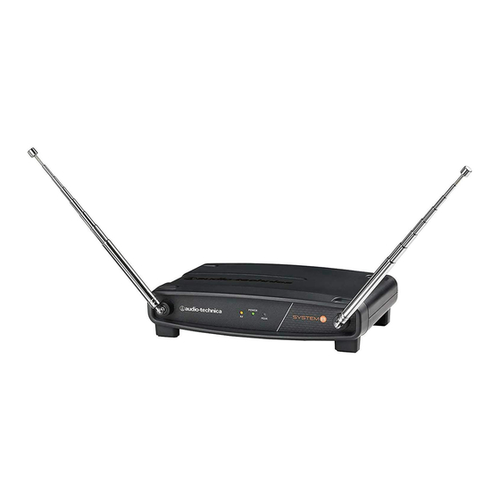
Position the two antennas at 90° in the form of a “V, ” or position the left (“signal”) antenna vertically and the right (“ground”) Each System 8 professional VHF wireless system includes a receiver antenna horizontally, in the shape of an “L ” (Fig. A). Use the position and either a body-pack transmitter or a handheld microphone/ that performs better in your operating environment. -
Page 3: Receiver Controls And Functions
System 8 Installation and Operation Receiver Controls and Functions POWER SYSTEM PEAK POWER SYSTEM PEAK Figure A — Front Panel Controls and Functions 1. ANTENNAS: Position the “signal” antenna (1a) and POWER SYSTEM PEAK “ground” antenna (1b) as shown to the right and above right. Fully extend both antennas by pulling on the endcaps. - Page 4 System 8 Installation and Operation Transmitter Setup Controls and Functions Battery Selection and Installation Two alkaline AA batteries are recommended. When inserting the battery, observe correct polarity as marked inside the battery compartment. Gain Trimmer LEVEL Battery Compartment Screwdriver LR6,AA...
- Page 5 System 8 Installation and Operation Instrument Trimmer (INST) Microphone Trimmer (MIC) Screwdriver Battery Compartment Figure D — UniPak Transmitter ® UniPak ® Transmitter Battery Installation 1. Slide off the battery cover as shown in Figure D. 2. Carefully insert two fresh AA alkaline batteries, observing polarity markings.
-
Page 6: System Operation
System 8 Installation and Operation System Operation Return the screwdriver to its clip and close and secure the lower body. No further transmitter gain adjustments should be needed, as long as the acoustic input does not change significantly. Turn down the receiver volume control and the mixer/amplifier level before starting up the wireless system. -
Page 7: Specifications
System 8 Installation and Operation System Operating Frequencies Application Freq. Code Freq. (MHz) • Traveling frequencies: 169.505 (Normally work anywhere in the U.S.A. and 170.245 Canada.) Not all frequencies available in all areas 171.905 outside the US. Please check with local regulations. - Page 8 Audio-Technica U.S., Inc. 1221 Commerce Drive, Stow, Ohio 44224 USA +1 (330) 686-2600 Audio-Technica Limited Old Lane, Leeds LS11 8AG England +44 (0) 113 277 1441 Audio-Technica (Greater China) Limited Unit K, 9/F ., Kaiser Est. (Ph.2) 51 Man Yue St. Kowloon, HK. +852-2356-9268 Audio-Technica (S.E.A.) Pte.