
Related Manuals for Audio Technica ATW-201


Summary of Contents for Audio Technica ATW-201
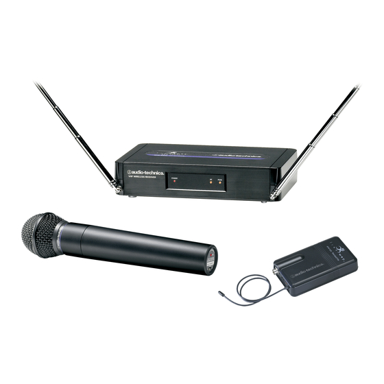
- Page 1 200 Series Professional VHF Wireless Systems ATW-201 UniPak ATW-201/G Guitar System ATW-201/H Headworn Microphone System ATW-201/L Lavalier Microphone System ATW-202 Handheld Microphone System Installation and Operation ™ System...
- Page 2 Wireless Essentials ™ microphones and cables, available sepa- rately, are pre-terminated for use with any ATW-201 system. Because 200 Series packaging is designed to hold all versions of the system, some compartments in the carton are intention- ally left empty.
-
Page 3: Receiver Installation
Location For best operation the receiver should be at least 3' (1 m) above the ground and at least 3' (1 m) away from a wall or metal surface to minimize reflections. Keep the receiver antennas away from noise sources such as digital equipment, motors, automobiles and neon lights, as well as away from large metal objects. -
Page 4: Transmitter Setup
UniPak ™ Transmitter Input Connection Connect an audio input device (microphone or guitar cable) to the input connector on the bottom of the transmitter. The cable connector latches automatically when inserted into the transmitter jack. To unlatch and remove the connector, simply pull up on the connector’s knurled metal collar. -
Page 5: System Operation
Adjust the output level of the receiver so the highest sound pressure level going into the microphone (or the loudest instrument playing level) causes no input overload in the mixer, and yet permits the mixer level controls to operate in their “normal” range (not set too high or too low). - Page 6 5. Please note that wireless frequencies are shared with other radio services. According to Federal Communications Commission regulations, “Wireless microphone operations are unprotected from interference from other licensed operations within the band. If any interference is received by any Government or non-Government operation, the wireless microphone must cease operation...”...
-
Page 7: Specifications
In the interest of standards development, A.T.U.S. offers full details on its test methods to other industry professionals on request. Optional System Accessories AT-GCW Hi-Z instrument/guitar cable with with ATW-201/G systems. XLRW Connecting cable for UniPak transmitter with an XLRF-type input connector, for Lo-Z microphones with XLRM-type output terminations. - Page 8 Receiver Power Supply Release Tab Figure A (p. 3) Antennas Figure B (p. 3) Receiver Controls and Functions Figure C (p. 3) DC 12V IN AF OUT SQUELCH Figure D (p. 3)
-
Page 9: Transmitter Controls And Functions
Microphone Guitar Trimmer Trimmer (MT) (GT) Battery-Save Switch Battery Polarity (under screwdriver clip) Diagram Figure E (p. 4) Figure G (p. 4) Figure H (p. 5) Power Switch Battery Condition Off/Standby/On Indicator INPUT POWER BATT. ANT Input Antenna Connector Figure I (p. -
Page 10: Visit Our Website
One-Year Limited Warranty Audio-Technica professional wireless systems purchased in the U.S.A. are warranted for one year from date of purchase by Audio-Technica U.S., Inc. ( A. T .U.S.) to be free of defects in materials and workmanship. In event of such defect, product will be repaired promptly without charge or, at our option, replaced with a new product of equal or superior value if delivered to A.