Table of Contents

Related Manuals for Audio Technica ATW-601


Summary of Contents for Audio Technica ATW-601
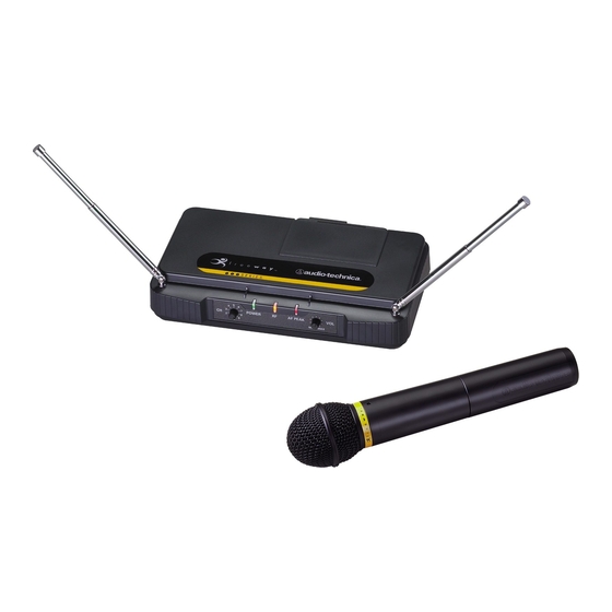
- Page 1 600 Series Professional UHF Wireless Systems ATW-601 UniPak ATW-601G Guitar System ATW-601H Headworn Microphone System ATW-601L Lavalier Microphone System ATW-602 Handheld Microphone System Installation and Operation ™ System...
- Page 2 AT-GCW guitar cable ( /G), a PRO 8HEcW headworn microphone ( /H) or an AT829cW lavalier mic ( /L) for particular applications. All A-T Wireless Essentials cables, available separately, are pre-terminated for use with any ATW-601 system.
-
Page 3: Receiver Installation
Location For best operation the receiver should be at least 3' (1 m) above the ground and at least 3' (1 m) away from a wall or metal surface to minimize reflections. Keep the receiver antennas away from noise sources such as digital equipment, motors, automobiles and neon lights, as well as away from large metal objects. -
Page 4: Transmitter Setup
Transmitter Setup UniPak ™ Transmitter Input Connection Connect an audio input device (microphone or guitar cable) to the input connector on the bottom of the transmitter. A number of Audio-Technica professional microphones and cables are available separately, pre-terminated with a UniPak input connector (see “Optional System Accessories”... -
Page 5: System Operation
RF signals. Input Level Adjustment An input trimmer control (Trim) in the transmitters enables you to maximize performance for a particular microphone or guitar sensitivity, or to adjust for different acoustic input levels. Adjusting Input Level - UniPak Transmitter Slide the battery cover off the top part of transmitter and remove the screwdriver from its clip (Fig. - Page 6 RF performance. Please note that wireless frequencies are shared with other radio services. According to Federal Communications Commission regulations, “Wireless microphone operations are unprotected from interference from other licensed operations within the band. If any interference is received by any Government or non-Government operation, the wireless microphone must cease operation...”...
-
Page 7: Specifications
In the interest of standards development, A.T.U.S. offers full details on its test methods to other industry professionals on request. Optional System Accessories AT-GCW Hi-Z instrument/guitar cable with with ATW-601/G systems. XLRW Connecting cable for UniPak transmitter with an XLRF-type input connector, for Lo-Z microphones with XLRM-type output terminations. -
Page 8: Receiver Power Supply
Receiver Power Supply Release Tab Figure A (p. 3) Antennas Figure B (p. 3) Receiver Controls and Functions Figure C (p. 3) AF OUT DC 12V IN SQUELCH Figure D (p. 3) -
Page 9: Transmitter Controls And Functions
Trim Battery Control Polarity Diagram Channel Selector Figure E (p. 4) Figure G (p. 4) Figure H (p. 5) Battery Condition Indicator Power Switch Audio Input Figure I (p. 4) Connector Transmitter Controls and Functions Serial Number Figure F Trim Battery Control Polarity... -
Page 10: Visit Our Website
One-Year Limited Warranty Audio-Technica professional wireless systems purchased in the U.S.A. are warranted for one year from date of purchase by Audio-Technica U.S., Inc. ( A. T .U.S.) to be free of defects in materials and workmanship. In event of such defect, product will be repaired promptly without charge or, at our option, replaced with a new product of equal or superior value if delivered to A.