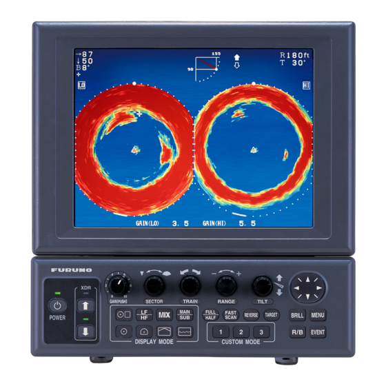
Furuno CH-300 Installation Manual
Dual-frequency searchlight sonar
Hide thumbs
Also See for CH-300:
- Operator's manual (124 pages) ,
- Operator's manual (4 pages) ,
- Installation manual (108 pages)
Table of Contents
Advertisement
Quick Links
Advertisement
Table of Contents

Related Manuals for Furuno CH-300


Summary of Contents for Furuno CH-300
- Page 1 DUAL-FREQUENCY SEARCHLIGHT SONAR CH-300 www.furuno.co.jp...
- Page 2 Nishinomiya, 662-8580, JAPAN Telephone : +81-(0)798-65-2111 : +81-(0)798-65-4200 Printed in Japan All rights reserved. Pub. No. IME-13250-B (YOSH ) CH-300 The paper used in this manual is elemental chlorine free. ・FURUNO Authorized Distributor/Dealer A : APR B : SEP . 07, 2007...
- Page 3 Also confirm that the transducer will not loosen by ship's vibration. The installer of the equipment is solely responsible for the proper installation of the equipment. FURUNO will assume no responsibility for any damage associated with improper installation. WARNING Install the specified transducer tank in accordance with the installation instructions.
- Page 4 CAUTION Ground the equipment to prevent electrical shock and mutual interference. Observe the following compass safe distances to prevent deviation of a magnetic compass: Standard Steering 0.80 m CH-302/ MU-100C CH-303 0.55 m IF-8000 0.95 m CH-302 0.30 m 0.30 m CH-256 Install the monitor unit MU-100C out of direct sunlight.
-
Page 5: Table Of Contents
TABLE OF CONTENTS SYSTEM CONFIGURATION ·······················································································iv EQUIPMENT LISTS ····································································································v 1. MOUNTING ·············································································································1-1 1.1 Monitor Unit/Control Unit ...1-1 1.2 Control Unit ...1-5 1.3 Transceiver Unit ...1-7 1.4 Hull Unit ...1-8 1.5 Interface Unit...1-22 1.6 Motion Sensor MS-100 (option)...1-23 1.7 Clinometer BS-704 (option) ...1-24 2. -
Page 6: System Configuration
SYSTEM CONFIGURATION INTERFACE UNIT IF-8000 Note 2 Navigator Display Unit VGA Ext. Monitor TRANSCEIVER UNIT CH-303 DATA/VIDEO OUT Speaker Motion Sensor Note 1: MU-100C is the standard supply monitor unit. An external monitor may be connected via the interface unit (option). The drawing above shows the system configuration with the MU-100C. -
Page 7: Equipment Lists
CH-3042 Flange CH-2543 Assembly Kit for CH-2544 field SHJ-0006 Shaft 06-007-1572 Sonar Oil 4 lit. EQUIPMENT LISTS Code no. Not supplied with blackbox type Not supplied with unibody type For blackbox type (not required for MU-151C) 400 stroke 250 stroke... - Page 8 Options Name Remote Controller CH-256-E Interface Unit IF-8000 Motion Sensor MS-100 Monitor Unit MU-100C Control Unit CH-302-E Clinometer BS-704 Loudspeaker SC-05WR Signal Cable S06-9-5 Rectifier RU-1746B-2 MJ-A6SPF0012-050 MJ-A6SPF0012-100 Cable assy. MJ-A6SPF0011-050 MJ-A6SPF0011-100 OP06-15-1.5 NEW Control Unit OP06-15-5 NEW Separate Kit OP02-83-1.5 OP02-83-5 OP06-16...
-
Page 9: Monitor Unit/Control Unit
Monitor Unit/Control Unit This searchlight sonar has two types of shipments, unibody type which is shipped with monitor unit, and blackbox type which is shipped without a monitor unit, but has an interface unit. For blackbox type, see page 1-5. - Page 10 1. MOUNTING 3. Coat threads of upset screws (M6x16, 2 pcs.) used to fasten bracket to mounting base. 4. Fasten the bracket to the mounting base with two upset screws. (Use the upper holes to tilt the monitor unit 20 ; lower holes to tilt it 9 .) Upset Screw Bracket (rear view) Bracket, rear view...
- Page 11 Flush mounting Flush mounting for unibody (Type: OP06-16, Code no.: 006-556-300) Name Fixing metal Self-tapping screw Hex. bolt 1. Cut out a hole (W287 x H297) in the mounting location. 2. Fasten monitor/control unit with the fixing metal (supplied) and four hex. bolts (M4x12, supplied).
- Page 12 1. MOUNTING 4. Coat threads of upset screws (M6x16, 2 pcs.) used to fasten bracket to mounting base. 5. Fasten the bracket to the mounting base with two upset screws. (Use the upper holes to tilt the monitor unit 20°; lower holes to tilt it 9°.) Flush mounting for monitor unit (Type: OP06-17, Code no.
-
Page 13: Control Unit
1.1.4 Blackbox type The blackbox type requires a VGA monitor, connected via the interface unit IF-8000. Supply commercial monitor and interconnection cable (Max. length 15 m with Dsub-15P connectors of male, three rows of 15 pins). The monitor used should satisfy the specifications shown below. VGA type ANALOG RGB 0.7 Vpp, positive polarity TTL level H, V, Negative polarity... - Page 14 1. MOUNTING To mount the control unit separate from the monitor unit, the optional control unit separate kit is required. Mount the control unit same as the above procedure. See the outline drawing at the back of this manual to mount. Type: OP06-15-1.5 NEW Type: OP06-15-5 NEW Name...
-
Page 15: Transceiver Unit
Transceiver Unit 1.3.1 General mounting considerations The mounting location should be well ventilated and dry. The unit can be mounted on a bulkhead or the deck. The maximum cable length between the transceiver unit and the raise/lower drive unit is 50 m. The maximum cable length between the transceiver unit and the monitor (interface) unit is 10 m. -
Page 16: Hull Unit
An obstacle in the fore direction not only causes a shadow zone but also aerated water, resulting in poor sonar performance. Be sure to locate the transducer well away from any obstacle in the fore direction. - Page 17 1.4.3 Transducer tank Tank length Shorten the transducer tank so the transducer is lowered into water as deep as possible. Pay particular attention to the tank length Lt. Determine the length of the main shaft. Length of main shaft = Lt + 200 mm (for 400 stroke) Length of main shaft = Lt + 50 mm (for 250 stroke)
- Page 18 1. MOUNTING Mounting of transducer tank Install the transducer tank referring to the hull unit outline drawings at the back of this manual. Note 1: When making a retraction tank locally, the inside diameter of the retraction tank should be 190 0.5 as shown in the outline at the back of this manual.
- Page 19 1. Calculate necessary length of main shaft from the length of retraction tank Lt and cut off the unnecessary portion. Supplied length: 2.2 m or 3.8 m Lt + 200 mm for 400 mm travel Lt + 50 mm for 250 mm travel Take care not to damage.
- Page 20 1. MOUNTING 4. Fully screw main shaft into the soundome neck, and then unscrew by four turns. Coat threads with CEMEDINE HIGH SUPER. Applying CEMEDINE HIGH SUPER to main shaft 5. Screw in main shaft completely. 6. As shown in the drawing below, confirm that the narrowest gap between the tank guide, and retraction tank in the range (20 to 170 mm) is within 0.5 mm.
- Page 21 7. If the gap at a side is more than 0.5 mm, install shim(s) to make the gap within 0.5 mm. a) Unscrew four M10x50 bolts. b) Unscrew four countersunk screws, then attach shim(s) with the countersunk screws as shown below. Flat washer Hex.
- Page 22 1. MOUNTING The table below shows tank length and necessary shim thickness. In addition, the shim thickness shown is for one side. For example, when cutting the 1800 mm tank to 800 mm, the tank inside diameter is 191.25 mm, and shim thickness is 2.5 mm as shown the table in below.
- Page 23 8. Coat the inside of the tank guide with ADHESIVE 1104 200G. Then, fasten tank guide at the neck of the main shaft securely with M10X80 bolts. Hex. bolt (M10X80) Bow mark Tank guide attachment 9. Pass the main shaft through the flange assembly. 10.
- Page 24 1. MOUNTING 11. Align the bow mark on the soundome with the bow mark on the flange assembly, and then fix the main shaft with and shaft retainer. 12. Fix the jubilee clip to the main shaft. Shaft retainer Note: Attach the shaft retainer so it is 15 mm from the top of the shaft. The soundome is then placed 10 mm above the bottom of tank when retracted.
- Page 25 18. Stand the soundome upright on top of the soundome packing. Fill the soundome with oil (supplied) so the level is 5 cm from the top of the soundome. Keep the soundome packing for future use. Ball wrench Filling the soundome with sonar oil Socket head cap screw 10pcs, M5x30 Spring washer O-ring Remove.
- Page 26 1. MOUNTING Keep oil away from eyes. Where protective goggles when working with the oil. The oil cause inflammation of the eyes. Do not touch the oil. The oil can cause inflammation of the skin. Wear protective gloves when working with the oil. Do not ingest the oil.
- Page 27 Note 2: When the soundome is painted (to keep marine life off the transducer), observe the following precautions: Use only anti-fouling paint type MARINE STAR 20 (Manufacture: Chugoku Marine Paint Co., Ltd., Japan). Paint only the plastic portion of the dome. Painting the metal parts causes electric corrosion.
- Page 28 1. MOUNTING 23. Fix the shaft sleeve and retraction tank with hex bolts, flat washers and spring washers. Shaft retainer 1-20 Hex bolt 15 mm 1-2 mm Jubilee clip Main shaft 10 mm...
- Page 29 Checking manual raise/lower of soundome with hand crank Perform this check after all wiring has been completed. CAUTION Turn the main power off before this check, otherwise the raise/lower motor action may cause injury. 1. Turn off the breaker on the hull unit. 2.
-
Page 30: Interface Unit
1. MOUNTING Interface Unit The interface unit is shipped with the blackbox type to enable connection of a monitor. Note that this unit is not necessary when using monitor MU-151C. 1.5.1 General mounting considerations The mounting location should be well ventilated and dry. Avoid locations subject to water splash or rain. -
Page 31: Motion Sensor Ms-100 (Option)
Motion Sensor MS-100 (option) The MS-100 measures ship’s pitching and rolling angles with a sensor, using the principles of the gyroscope. The MS-100 is free from error caused by ship’s vertical and horizontal motion. Therefore, it can be installed at any convenient location. -
Page 32: Clinometer Bs-704 (Option)
Clinometer BS-704 (option) The clinometer detects ship’s inclination caused by ship’s rolling, pitching and its output is used to stabilize the sonar beam against rolling and pitching. The clinometer is, in principle, a pendulum. It measures the inclination of the ship by sensing the direction of gravity acted on it and therefore when installed on a ship, it should be placed on or near the rotation axes of the ship’s rolling... -
Page 33: Wiring Among Units
The raise/lower drive motor and breaker are different depending on ship’s mains. Install the mains switch for the sonar where it can be easily accessed. Turn off this switch when the sonar is not being used, to reduce power consumption and to prevent the transducer from slipping by vibration. - Page 34 2. WIRING Monitor/control unt CH-302/MU-100C Note 3 06S4078 (5/10m) Loudspeaker (w/cable) Ext. KP 06S4080 (15/30/50m) Note 1: Optional cable between the monitor unit and control unit for separate installation -MJ-A10SPF0002-015 (1.5m) -MJ-A10SPF0002-050 (5m) Note 2 a b<15m Note 3: MU-151C can be connected for MU-100C. In this case, the monitor and control units should be mounted seprately.
- Page 35 Interface unit IF-8000 Note 3 06S4078 Note 3 (5/10m) MJ-A10SPF0002-050 06S4078 (5m) (5/10m) SPEAKER Loudspeaker (w/cable) Ext. KP Monitor unit Clinometer Note 1: Two interface units may be connected. Note 2: For interface unit, the external monitor (user supply) is required. Note 3 *a b<15m Note 1 Navigation equipment...
- Page 36 2. WIRING Transceiver Unit Connect the cables as shown in the figure below. *Note SPEAKER External loudspeaker SC-05WR 06S4080 Hull unit External KP CH-304/CH-305 *: Fix the braided shield with the clamp. 06P0254 7P-NH connector (local supply) Tie these cables with locking spacer.
- Page 37 Synchronizing Transmission with Echo Sounder or Other Sonar To synchronize transmission of the CH-300 with an echo sounder or other type of sonar, connect it as shown below. H7P-SHF (local supply) Transceiver unit 06P0254 EXT_SW Connection of transceiver unit to other sonar/echo sounder...
- Page 38 2. WIRING Hull Unit Pass the cables to the 06P0257 Board, through the cable protectors. 06P0257 06P0243 *Note: Fix the braided shield with cable clamp. Fasten glands securely by hand. *Note *Note *Note Power switch Should always be in up position (ON). Earth Connect to ship's earth.
- Page 39 Note 3: Connect control unit or navigator equipment to either interface unit or monitor unit (supplied by FURUNO). Note 4: When connecting the monitor unit MU-100C to the interface unit, or two interface units in parallel to the transceiver unit, the length of cables should be as shown in the figure on next page.
-
Page 40: I/O Sentences
2. WIRING 06S4078 Transceiver unit External monitor 06S4078 Transceiver unit I/O Sentences Talkers may be chosen from among GP, LC, LA, DR, DE and other (II). Refer to “NAV DATA” in System Setting 1 menu. Sentences External monitor 06S4078 Display unit Interface MU-100C unit... -
Page 41: General Checks
ADJUSTMENTS General Checks Check Item Retraction tank level Clearance between transducer and bottom of retraction tank when transducer is completely retracted by hand crank Transducer travel (lowered by hand clank) Note: For checking purposes, a clearance of approximately 1 meter is required beneath the bottom of the transducer. -
Page 42: Checking Tx Frequency
3. ADJUSTMENT Check Item Wiring check Rejecting source of noise and interference Earth Ship’s mains voltage Watertightness Checking TX Frequency Check the TX frequency after installing the equipment. 1. Press the MENU key to open the menu. 2. Press the cursor pad to select SYS at the top of the menu display. 3. - Page 43 ** SYSTEM MENU ** SYSTEM RANGE-SONAR MODE RANGE-VERTICAL MODE RANGE-E/S MODE RANGE-TRACK MODE COLOR PALETTE LANGUAGE SYSTEM BACKUP LOAD BACKUP DATA HEADING OFFSET, DRAFT OFFSET ADJ MOTION SENSOR TX FREQ ADJUST TEST TEST PATTERN DEMO MODE DEFAULT : SELECT System menu 5.
- Page 44 3. ADJUSTMENT Heading Alignment Setting The heading line can be compensated from the system menu ( –180 to +180 ). 1. Locate a target (buoy, etc.) in the bow direction and display it on the screen at close range, read deviation. The heading alignment is correct when the target is displayed at 12 o’clock on the screen.
-
Page 45: Setting For Synchronizing Transmission With Other Equipment
Setting for Synchronizing Transmission with other Equipment To synchronize transmission with other echo sounder (see paragraph 2.2), do as follows: 1. Press the MENU key to display the menu. 2. Press ◄ to select COM1 at the top of menu display. MENU COM1 TX POWER... -
Page 46: Setting For Satellite Compass
3. ADJUSTMENT Setting for Satellite Compass FURUNO Satellite Compass SC-50/110 can be connected to feed rolling/pitching data to this equipment. Connect the SC-50/110 sensor to the NMEA/SATELLITE COMPASS port, and set up this port as below. 1. Press the MENU key to show the menu. - Page 47 ** SYSTEM SETTING 2 ** MENU GAIN SETTING PROTECT : HORZ/HISTORY HORZ/VERT ZOOM HORZ/PLOTTER EMPHASIS MODE STABILIZER AUTO RETRACTION SPEED ALARM/MESSAGE : : DOT SWEEP INDICATOR DEFAULT SETTING : NO MAXIMUM ALLOWABLE SPEED IS 15 KNOTS WHILE SOUNDOME IS BEING RETRACTED.
-
Page 48: Setting Of Motion Sensor/Satellite Compass
3. ADJUSTMENT Setting of Motion Sensor/Satellite Compass When connecting the motion sensor, clinometer or satellite compass, enter ship’s roll and pitch angles as shown below. Note that the adjustment can be done only when connected to the MOTION SENSOR port. For the satellite compass, however, do not duplicate this adjustment;... -
Page 49: System Back Up
System Back Up After setting up the equipment, follow the procedure below to back up system settings. Backup data can be loaded in the event of equipment trouble, to restore previous system settings. 1. Press the MENU key to display the user menu. 2. -
Page 50: Setting Of Interface Unit
3. ADJUSTMENT Setting of Interface Unit Set DIP switch S1 in the interface unit as follows. A unit is connected to DATA/VIDEO OUT port of the interface unit : all OFF. Nothing is connected to DATA/VIDEO OUT port of the interface unit: all ON. Processor Unit Processor... - Page 64 This page is intentionally left blank.
- Page 65 Y. Hatai...
- Page 66 D-10 Y. Hatai...
- Page 67 D-11 Takahashi T Takahashi T...
- Page 68 D-12...
- Page 69 D-13...
- Page 70 D-14...
- Page 71 D-15...
- Page 72 D-16 Y. Hatai...
- Page 73 D-17...
- Page 74 This page is intentionally left blank.
- Page 75 D-18...
- Page 76 D-19...
- Page 77 D-20...
- Page 78 D-21...
- Page 79 D-22...
- Page 80 CLINOMETER BS-704 TITLE CH-300 E. MIYOSHI 名 称 2周波サーチライトソナー TAKAHASHI.T 相互結線図 Y. Hatai MASS NAME DUAL-FREQUENCY SEARCHLIGHT SONER C1325-C01- A INTERCONNECTION DIAGRAM FURUNO ELECTRIC CO., LTD. MJ-A7SPF REMS0-N REMS1-N REMR0-N REMR1-N REMR2-N +12V SC-50/110 J11 ROLL ROLL J12 PITCH PITCH...
- Page 81 CH-300 E. MIYOSHI 名 称 2周波サーチライトソナー(I/Fユニット使用) TAKAHASHI.T Y. Hatai 相互結線図 MASS NAME DUAL-FREQUENCY SEARCHLIGHT SONER (W/ I/F UNIT) C1325-C02- B INTERCONNECTION DIAGRAM FURUNO ELECTRIC CO., LTD. 外部モニター VGA MONITOR リモートコントローラ REMOTE CONTROLLER CH-256 操作部 CONTROL UNIT CH-302 MJ-A7SPF DISP TRXTD-A...