
Related Manuals for Scytek electronic ASTRA 4000RS Series


Summary of Contents for Scytek electronic ASTRA 4000RS Series
- Page 1 ASTRA 4000RS SERIES VEHICLE SECURITY SYSTEM WITH REMOTE START W W I T H S E P E R A A T E L O C K / U N L O C K B U T T O N S...
- Page 2 Limited Lifetime Warranty This vehicle security system is warranted to the original purchaser, to be free from defects in material and workmanship. The manufacturer will repair or replace at its option, and free of charge for the first twelve (12) months, any part that proves defective in material or workmanship under normal installation, use, and service, provided the product is returned to the manufacturer freight prepaid.
-
Page 3: Table Of Contents
Table of Contents About Your System ............Page 1 Remote Transmitters . -
Page 4: About Your System
To ensure the safety and security of the system while it is remote started, the Astra 4000RS SERIES employs several safeguards. In the event the alarm is triggered while the engine is remotely running, the remote start will immediately shutdown to prevent unauthorized users from attempting to drive the vehicle. -
Page 5: Remote Transmitters
Button 5 Button 3 Button 4 The Astra 4000RS Series comes equipped with the 5-button Remote Transmitters used to control system operations. Button 1 Arms the system and when held for 5 seconds, activates the system’s Panic feature. Button 1 also locks the doors when the system is in Valet Mode. -
Page 6: Adding/Replacing Transmitters
6. Turn off the ignition key. Two Car Operation If two vehicles are equipped with Astra 4000RS Series system, for convenience both can be operated using the same remote transmitter. If all four transmitters are to be used with both cars, program transmitters A and B into the first vehicle in the manner described above. -
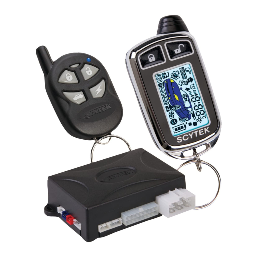
Page 7: Optional 2-Way Lcd Remote Transmitter Description
Button 4 Button 5 The Astra 4000RS-2W-1 is supplied one 2-way LCD remote transmitter, offering increased range and confirmation of any activated features. Button 1 Arms the system and when held for 5 seconds, activates the system’s Panic feature. Button 1 also locks the doors when the system is in Valet Mode. -
Page 8: Lcd Transmitter Battery Replacement
1. Press and hold Buttons 2 and 3 until the remote beeps four times. · The fan and clock will be shown indicating automatic start mode is entered. 2. Press Button 2 until the desired hour is displayed. Astra 4000RS Series - Page 5... -
Page 9: Lcd Backlight
· The transmitter will beep three times. 2. Release Button 5. · The transmitter will beep once. · The LCD panel will play a tone if the sounds are enabled or "off" will be displayed if the chirps are disabled. Page 6 - Astra 4000RS Series... - Page 10 · The transmitter will beep four times. 2. Release Button 5. · The transmitter will beep once. · The LCD panel will play a tone if the sounds are enabled or "off" will be displayed if the chirps are disabled. Astra 4000RS Series - Page 7...
-
Page 11: System Operation
* During Disarming, if the system was triggered while away from the vehicle, the siren will chirp 3 times, the parking lights will flash 3 times, and the LED will flash to indicate triggered zone. See Tamper Alert for zone listing. If the optional Dome Activation Feature was installed. Page 8 - Astra 4000RS Series... -
Page 12: Tamper Alert
= shock sensor Silent Arming/Disarming The Astra 4000RS Series system can be programmed to operate the system without Arm and Disarm chirp indications. When programmed for full-time silent operation, the siren will sound only when the system is triggered. -
Page 13: Panic Mode
5. The vehicle will now be able to start. Optional Coded Emergency Override As an extra measure of security, the Astra 4000RS Series is equipped with an optional Coded Emergency Override feature. Once an Emergency Override Code is chosen and programmed during installation, the system can no longer be disarmed using the standard override procedure. -
Page 14: Automatic Rearming
DRIVER CALLING/PAGE FEATURE The Astra 4000RS Series is equipped with a driver calling or paging feature that allows the system to send a page to the LCD transmitter in the event the transmitter has been misplaced or lost (within 1500... -
Page 15: Remote Start Feature
1. Unlock the doors manually or by pressing Disarm Button on the Remote Transmitter. 2. Turn on the ignition. 3. Press the Brake Pedal to disengaged the remote start. · The parking lights will turn Off. Page 12 - Astra 4000RS Series... -
Page 16: Automatic Start Mode
To turn off Auto Starting do one of the following: · Turn ignition On. · Arm and then Disarm the system · Alarm or Panic the system * Automatic Start Mode will stay active for 24 hours only. Astra 4000RS Series - Page 13... -
Page 17: Extended Features
Remote Transmitter, and remain on for 30 seconds or until the ignition is turned on. Auxiliary Function Outputs The Astra 4000RS Series are equipped with 1 Auxiliary Channel Output allowing the convenience features of the system to be further expanded. This output can be programmed for pulsed, timed, or latched operation, and used to add a number of optional features such as: power trunk release, power window activation, power sunroof control, auxiliary lighting, audio/video system control, and more. -
Page 18: System Installation
6. Verify with the owner, the mounting locations for all visible components, including the LED and Override switch. Verify with the owner, the optional features of the Astra 4000RS Series and the features that must be programmed during installation. 8. Inspect and perform a function test of all vehicle systems before and after the installation. -
Page 19: Mounting The Control Unit
Suggested mounting locations include air conditioning ducts, dashboard braces, or center console supports. During proper operation, the shock sensor will detect impacts to the vehicle only and will not usually be triggered by slow rocking movements of the vehicle like those caused by wind. Page 16 - Astra 4000RS Series... -
Page 20: System Wiring
Connect to the wire that requires a ground pulse to disarm the factory security system. Pin 11 BLUE/ORANGE: Ground When Running Output (-) 500 mA. Connect to an optional factory security bypass module if required. Astra 4000RS Series - Page 17... -
Page 21: Plug-In Connectors
· BLUE WIRE - negative unlock output (-) 500mA. · RED WIRE - (+) Not used · GREEN WIRE - negative lock output (-) 500mA. 5-PIN White Remote Start Relay Module: Connect to Remote Start 6 Wire Relay Module Page 18 - Astra 4000RS Series... -
Page 22: Jumper Settings
Parking Light Output. Selects the polarity (+/-) for the output of the on-board Parking Light relay. Left Pin and Center Pin = negative Right Pin and Center Pin = positive default setting shown Astra 4000RS Series - Page 19... -
Page 23: System Programming
5. Extended Parking Lights. When Enabled, upon Disarming Parking lights will turn On for 30 seconds or until the Dome light turns Off. 6. Ignition Door Locking / Override Code Set. This dual program branch selects Ignition Door Page 20 - Astra 4000RS Series... -
Page 24: Branch Table
11. Ignore Open Door Report. Bypasses the open zone warning chirps for vehicles equipped with a residual dome light circuit that remains on for a period of time after closing the door. 12. Auxiliary 1 Mode. Selects from momentary, 10 second timed, or latched operation for Auxiliary 1. Astra 4000RS Series - Page 21... - Page 25 22. Ignition 2 Relay Program. Selects one of three operating modes for the Ignition 2 relay output: Ignition 2, Accessory 2, or Starter 2. 23. Ignition Door Lock Mode. Selects Lock when engine RPM exceeds twice the idle, and Lock 3 seconds after ignition is turned On. Page 22 - Astra 4000RS Series...
-
Page 26: Relay Diagrams
Relay Diagrams Positive Dome Light Activation Negative Dome Light Activation Positive Horn Honk Negative Horn Honk Negative Glow Plug Starter Defeat/Anti-Grind Astra 4000RS Series - Page 23... -
Page 27: Door Lock Diagrams
Follow the diagrams below for connecting basic door lock systems. For Two Stage door lock systems (separately unlocks driver and passenger doors) see following pages. Negative Trigger Positive Trigger Green Blue Reverse Polarity Vacuum Adding Actuators Page 24 - Astra 4000RS Series... -
Page 28: Two Stage Door Lock Diagrams
Two Stage Door Lock Diagrams The Astra 4000RS Series can be wired for the Passenger Unlock output feature, allowing Two Stage Door Lock operation. When connected as shown below, disarming the system will unlock only the driver’s door. Pressing the Aux 1 button will unlock all doors. - Page 29 Two Stage Door Lock Diagrams cont’d Two Stage Reverse Polarity Aux 1 output (gray wire) Two Stage Adding Actuators Aux 1 output (gray wire) Page 26 - Astra 4000RS Series...
-
Page 30: Technical Information
4 Times - Brake Trigger is active ( Brake switch input is shorted to ground or incorrect) 5 Times - Unit is in Valet (service) mode, and start is disabled. LED LIGHT CAll/Valet/Emergency Override Switch Valet/Override Switch LED LIGHT RS-2W Series RS Series Astra 4000RS Series - Page 27... -
Page 31: Wiring Diagram
Gray - Trunk Release Out (-) 500ma Green/White - Brake Input (+) White - Parking Light Out (+/-) Red - +12V Input (+) ScyTek Electronics 11627 Cantara Street North Hollywood, CA 91605 www.scytek.net © ScyTek Electronics 2007 Astra 4000RS 3-27-07...