
Related Manuals for Scytek electronic G5.2W SERIES


Summary of Contents for Scytek electronic G5.2W SERIES
- Page 1 G5.2W, G2.2W A4.2W, A1.2W A1.1 SERIES VEHICLE SECURITY SYSTEM WITH REMOTE START PRODUCT MANUAL...
- Page 2 Limited Lifetime Warranty This vehicle security system is warranted to the original purchaser, to be free from defects in material and workmanship. The manufacturer will repair or replace at its option, and free of charge for the first twelve (12) months, any part that proves defective in material or workmanship under normal installation, use, and service, provided the product is returned to the manufacturer freight prepaid.
-
Page 3: Table Of Contents
Table of Contents About Your System ............Page 1 Remote Transmitters . - Page 4 Upgrade Options 2WC-KIT Two Way Pager upgrade kit Easy Plug and Play upgrade to a complete two way system. Increases range MobiLink 100 Smart phone upgrade Easy Plug and Play upgrade through the system- Antenna port 2 Way confirmation Arm/Disarm Remote Start On/Off Trunk Release Alert Notification...
-
Page 5: About Your System
About Your System G5, A4 Series is a Combination Vehicle Security and Remote Starting System , G2, A1 Series is a Remote Starting with keyless entry. With proper installation this system will provide superior protection and performance for many years to come. The Galaxy’s G5/G2 Series built-in remote starter is designed to offer maximum convenience by remote starting your vehicle’s engine, turning on the heater/air conditioner, and then running for a pre-determined time to provide a comfortable environment once you enter your vehicle. -
Page 6: Remote Transmitters
Remote Transmitters Standard Remote Transmitter Description Button 1 Button 2 Button 1 Button 2 Button 4 Button 4 Button 3 Button 5 Button 3 Button 5 A Series Remote Remote G Series Remote Button 1 Arms and Locks the system and when held for 5 seconds, activates the system’s Panic feature. Button 1 also locks the doors when the system is in Valet Mode. - Page 7 One Button Remote Transmitter A1.1 Series Remote Program transmitter(s): 1. Turn on the ignition key On, Off, 4 times and then back On on fifth time. · The siren will chirp 5 times. 2. Press and hold the Override switch for 5 seconds. ·...
-
Page 8: Remote Transmitter Description
Adding/Replacing Standard Remote Transmitters To replace lost or stolen transmitters or to add additional transmitters into the system, have all desired transmitters ready and follow the steps below. Note: Up to 4 one-way transmitters can be programmed to operate the system. Any previously stored transmitter will be erased if it is not programed within the following sequence To program the transmitter(s): 1. -
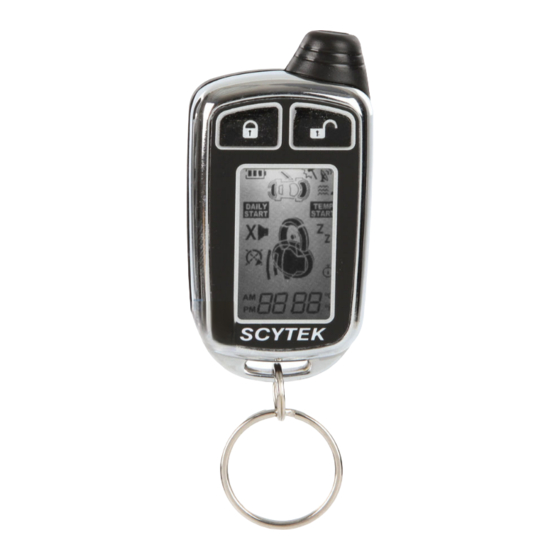
Page 9: 2-Way Lcd Remote Transmitter Description
2-way LCD Remote Transmitter Description Button 1 Button 2 Button 3 Button 4 Button 5 Page 1 Button 1 Arms and Locks the system and when held for 3 seconds, activates the system’s Panic feature. Button 1 also locks the doors when the system is in Valet Mode. Button 2 Disarms and Unlocks the system. -
Page 10: Setting The Time
Setting The Time The LCD display is equipped with a 12-hour clock Set the time: 1. Press and hold Buttons 2 and 3 for three seconds. · The remote will beep two times and three bars will be shown indicating time set mode is entered. 2. - Page 11 Automatic Cold Start Temperature Setting ( 2 step procedure, for second step see page 7 under “C st” ) The Automatic Cold Start setting sets the temperature threshold. If automatic start is set to cold temperature setting,the starter will activate every 2 or 4 hours if the temperature drops bellow the set value. (LED will flash slow in this mode) 1.
- Page 12 AUTO display starter autostart enabled features. 1. Press and hold Button 5 until the display shows AUTO. ·The transmitter will beep three times. 2. Release Button 5. · The LCD panel will display what starter auto start features are enabled. SPCL Program the pager time of a day clock from the internal Remote Starter clock, the remoter starter sends its time to the pager.
- Page 13 Pager Icon Description Battery Status Valet Starter Status Chirp Disable Timer Start Enabled Alarm Clock Daily Start Enabled Temperature Start Enabled Lock/Unlock Status Vibration Sensor Triggered Hood Sensor Triggered Trunk Sensor Triggered Vibraton On/Sound Off Sound On/Vibration Off Transmit G5.2W, G2.2W, A4.2W, A1.2W - Page 9...
-
Page 14: System Operation
System Operation Remote Arming/Locking The system monitors 5 independent areas ( zones ) while armed: doors, hood/ trunk, shock sensor, optional sensor input. To Arm and Lock the System: 1. Turn off the ignition. 2. Press Button 1. · The siren/horn will chirp/honk once. ·... -
Page 15: Tamper Alert
Tamper Alert If the system was triggered while away, the LED will flash to indicate which zone triggered the system after disarming and turning the ignition ON. The LED indication will repeat 8 times. LED Flashes (60 seconds): 1 flash optional sensor 2 flashes shock sensor 3 flashes... -
Page 16: Panic Mode
Panic Mode In the event of an emergency, the transmitter’s remote Panic feature can be used to instantly trigger the alarm/panic feature. To activate the Panic Mode: 1. Press and hold Button 1 for three seconds. · The alarm will sound. ·... -
Page 17: Automatic Rearming
· The siren will chirp each time the valet switch is pressed. 4. Within 5 seconds, press Button 3 on the transmitter. · The siren will chirp 3 times. 5. Press the valet switch the number of times equal to the desired code (from 1-15). 6. -
Page 18: Remote Start Features
Remote Start Features Remote Starting To Remote Start the System: 1. Be sure the system is not in Valet Mode. 2. Press and hold Button 4 for three seconds. · The parking lights will flash 4 times and turn on. ·... -
Page 19: Automatic Start Mode
Automatic Start Mode Automatic Start feature has three modes that will start the vehicle every one or two hours within a 24 hour period. 1. Timer Only Mode (factory default) The Automatic Start feature starts the vehicle automatically every one or two hours and runs for the preset Run Time. -
Page 20: Manual Transmission Remote Starting
Manual Transmission Remote Start Features Model: G5-M/G2-M 1- Tach wire must be connected , The system must learn RPM. 2- Hand brake must be connected. 3- Door trigger must be connected 4- Clutch override installed NOTE: MUST USE RELAY, SEE PAGE 28. Remote Starting ready With engine running and Hand-brake engaged put the vehicle transmission in neutral and remove the foot from the brake pedal, press the remote start button on your transmitter, parking lights will flash twice... -
Page 21: Extended Features
Extended Features Ignition Door Locking For added safety, the Ignition Door Locking feature allows vehicles equipped with power door lock systems to automatically lock the doors when the ignition is turned on. If a door is open when the ignition is turned on, the Ignition Door Locking feature is disabled to protect against locking the keys inside the vehicle. -
Page 22: System Installation
System Installation 1. Thoroughly read and become familiar with the installation instructions before beginning the installation. 2. Review system contents: Main Unit 1 or 2 One-way 5 Button Remote Transmitters (varies by model) 1 or 2 Two-way 5 Button LCD Remote Transmitters (varies by model) Siren Shock Sensor Harnesses... -
Page 23: Mounting The Control Unit
Mounting the Control Unit The control unit must only be mounted in the interior of the vehicle. Do not mount the main unit in the engine compartment. Choose a mounting location that will not be easily accessible to a thief, and will not interfere with the operation of any vehicle components such as foot pedals, steering column, air vents, seat rails, etc. -
Page 24: System Wiring
System Wiring 6-Pin Starter Harness Pin 1 RED WIRE A: Main Power Input A (+). Connect to the battery or constant power wire at the ignition switch with a minimum 25 Amp supply. Remove the fuse until the installation is complete and all wiring is checked. -
Page 25: Plug-In Connectors
Pin 12 GREEN WIRE: Negative Door Input (-). Connect to the door switch circuit wire that shows ground when the door is open. Pin 13 WHITE/BLACK WIRE: Hood/Trunk Pin Input (-). Connect the to the hood/trunk pin switch. The switch must provide a ground output when switch is opened. Pin 14 ORANGE WIRE: Armed Output (-) 500 mA. -
Page 26: Jumper Settings
4-Pin Black DBP Connector: The plug-in DBP connector port is located on the side of the main module. this DBP port may be used with the optional bypass modules for data bus interface. Jumper Selection Carefully separate the top and bottom halves of the main unit case. Once the cover is removed, the parking light polarity jumper will be visible next to the parking light relay. -
Page 27: System Programming
System Programming Entering System Programming This system is compatible with both the LCD two way transmitter or the standard transmitter, all system programming can be performed using either one. To enter System Programming using standard 5 button remote: 1. Turn the ignition switch to the ON position. 2. -
Page 28: Programmable System Options
Programming Branch Table Branch Feature Button 1 (default) Button 2 Button 3 Button 4 Arm Mode Manual Arming Passive Arming Auto Rearming Mode Disabled Enabled Reset Mobilink Arming Chirps Siren Chirps On Siren & Horn Chirps On Silent Data Bus Module ADS Ignition Door Locking Set Override Code Data Bus Module Fortin... - Page 29 2. Auto Rearming Mode. When selected, the system will automatically re-arm 30 seconds after it is disarmed . Restart Mobilink - Reset Mobilink (Galaxy Mobile) module. 3. Arming Chirps. Selects between normal and silent operation. Bypass Data Bus Module - set Bypass module to iDataLink 4.
- Page 30 16. Auxiliary 3 Output Mode. Selects between Channel 3, Factory Rearm output, or third Ignition ouput. 17. Lock After Start. When selected, the doors will automatically lock after remote starting. 18. Lock After Shutdown. When selected, the doors will automatically lock after remote shutdown. 19.
- Page 31 28. Extended Parking Lights. When selected, the parking lights will remain ON for 30 seconds after disarming the system. 29. Warn-Away Pager Report. When Enabled, Warn-Away report will be sent to the pager. If Disabled no Warn-Away report will be sent to the pager. 30.
-
Page 32: Relay Diagrams
Relay Diagrams Positive Dome Light Activation Negative Dome Light Activation Positive Horn Honk Negative Horn Honk Starter Defeat/Anti-Grind Negative Glow Plug Page 28 - G5.2W, G2.2W, A4.2W, A1.2W... -
Page 33: Door Lock Diagrams
Door Lock Diagrams Follow the diagrams below for connecting basic door lock systems. For Two Stage door lock systems (separately unlocks driver and passenger doors) see following pages. Negative Trigger Positive Trigger blue green Reverse Polarity Vacuum Adding Actuators G5.2W, G2.2W, A4.2W, A1.2W - Page 29... - Page 34 Two Stage Door Lock Diagrams The Galaxy 5000/2000RS-DBP Series is equipped with a dedicated Passenger Unlock output allowing Two Stage Door Lock operation. When connected as shown below, disarming the system will unlock only the driver’s door. Pressing the disarm button again will unlock all doors. Two Stage Negative Trigger Two Stage Positive Trigger Door Lock Inverter Green Wire...
- Page 35 Two Stage Door Lock Diagrams cont’d Two Stage Reverse Polarity Two Stage Adding Actuators G5.2W, G2.2W, A4.2W, A1.2W - Page 31...
-
Page 36: Technical Information
Technical Information FCC ID: OARRXAM2000 This device complies with Part 15 of FCC Rules. Operation is subject to the following two conditions: 1) This device may not cause harmful interference. 2) This device must accept any interference received, including interference that may cause undesired operation Built-in LED Light/Override/Valet/Call Switch into Antenna... -
Page 37: Shock Sensor Adjustment
Wiring Diagram Violet Starter Output Yellow Ignition 1 Output/ Input Orange Accessory Output Starter Harness Brown Ignition 2 Output +12V Battery Input #1 G5.2W, A4.2W +12V Battery Input #2 Green/White Brake Input(+) G2.2W, A1.2W Black/Gray Tachometer Input White/Red Auxiliary 2 Output (-)500mA Black/White Dome Light output (-)500mA (must use relay) Series...