Weider 8970 User Manual
Uk manual
Hide thumbs
Also See for 8970:
- Bedienungsanleitung (26 pages) ,
- Manuale d'istruzioni (26 pages) ,
- Manual del usuario (26 pages)
Table of Contents
Advertisement
Model No. WEEVSY10230
Serial No.
Write the serial number in the
space above for reference.
Serial Number Decal (under seat)
QUESTIONS?
As a manufacturer, we are
committed to providing com-
plete customer satisfaction. If
you have questions, or if there
are missing parts, please call:
08457 089 009
Or write:
ICON Health & Fitness, Ltd.
Unit 4
Revie Road Industrial Estate
Revie Road
Beeston
Leeds, LS118JG
UK
email: csuk@iconeurope.com
CAUTION
Read all precautions and instruc-
tions in this manual before using
this equipment. Save this manual
for future reference.
USER'S MANUAL
Visit our website at
www.iconeurope.com
Advertisement
Table of Contents

Related Manuals for Weider 8970


Summary of Contents for Weider 8970
- Page 1 Model No. WEEVSY10230 USER'S MANUAL Serial No. Write the serial number in the space above for reference. Serial Number Decal (under seat) QUESTIONS? As a manufacturer, we are committed to providing com- plete customer satisfaction. If you have questions, or if there are missing parts, please call: 08457 089 009 Or write:...
-
Page 2: Table Of Contents
Note: A PART IDENTIFICATION CHART and a PART LIST/EXPLODED DRAWING are attached in the centre of this manual. Remove the PART IDENTIFICATION CHART and the PART LIST/EXPLODED DRAWING before beginning assembly. WEIDER is a registered trademark of ICON Health & Fitness, Inc. -
Page 3: Important Precautions
IMPORTANT PRECAUTIONS WARNING: To reduce the risk of serious injury, read the following important precau- tions before using the weight system. 1. Read all instructions in this manual and in 13. Always disconnect the lat bar from the the accompanying literature before using the weight system when performing an exercise weight system. -
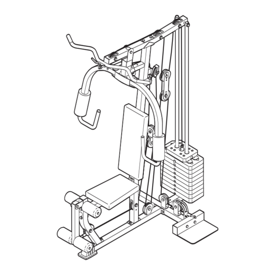
Page 4: Before You Begin
BEFORE YOU BEGIN Thank you for selecting the versatile WEIDER ® 8970 tions, please call our Customer Service Department at weight system. The weight system offers a selection of 08457 089 009. To help us assist you, please note the weight stations designed to develop every major muscle product model number and serial number before calling. -
Page 5: Assembly
ASSEMBLY • As you assemble the weight system, make sure Make Things Easier for Yourself all parts are oriented as shown in the drawings. Everything in this manual is designed to ensure • For help identifying small parts, use the PART that the weight system can be assembled suc- IDENTIFICATION CHART. - Page 6 3. Press a 38mm Square Inner Cap (41) into the tube on the Front Upright (6). Attach the Front Upright (6) to the Front Base (1) with the two indicated M10 x 65mm Carriage Bolts (57) and two M10 Nylon Locknuts (71). Do not tighten the Locknuts yet.
- Page 7 5. Slide the nine Weights (7) onto the Weight Guides (31). Make sure the pin grooves are on Lubricate the indicated side. Press the Weight Tube Bumper (14) into the Weight Tube (20). Insert the Weight Tube into the stack of Weights (7). Lubricate the indicated holes in the Top Weight (30) with grease.
- Page 8 8. Attach the Seat Frame (5) to the Front Upright (6) with an M10 x 70mm Bolt (58), an M10 x 77mm Bolt (60), three M10 Washers (26), and two M10 Nylon Locknuts (71). Don’t over tighten the Locknut on the M10 x 77mm Bolt; a cable will be attached to this bolt in step 23.
- Page 9 11. Lubricate an M10 x 80mm Allen Head Bolt (50) and both sides of two Plastic Washers (55) with Lubricate Welded grease. Attach the Right Butterfly Arm (11) to the Bushing Butterfly Frame (9) with the Bolt, the two Plastic Washers, two Butterfly Caps (54), two M10 Washers (26), and an M10 Nylon Locknut (71).
- Page 10 15. Wrap the Butterfly Cable (46) under a 90mm Pulley (38). Attach the Pulley and a pair of Pulley Covers (44) to the Double “U”-bracket (37) with Small an M10 x 53mm Bolt (61) and an M10 Nylon Tabs Locknut (71). Make sure the small tabs on the Pulley Covers are on top.
- Page 11 20. Wrap the High Cable (45) under a 90mm Pulley (38). Attach the Pulley and a pair of Pulley Covers (44) to the second set of holes from the top of the two Pulley Plates (36) with an M10 x Small 53mm Bolt (61) and an M10 Nylon Locknut (71).
- Page 12 25. Attach the Short Cable (83) to the Large “U”- bracket (82) with an M8 Washer (62) and an M8 Nylon Locknut (70). Do not completely tighten the Locknut; it should be tightened so that only two threads of the Cable show past the Locknut, as shown in the inset drawing.
- Page 13 30. Wrap the Low Cable (47) over a 90mm Pulley (38). Attach the Pulley and a pair of Pulley Covers (44) to the Large “U”-bracket (82) with an M10 x 53mm Bolt (61) and an M10 Nylon Locknut (71). Make sure the small tabs on the Pulley Covers are on the bottom.
- Page 14 34. Attach the Backrest (15) to the Front Upright (6) with two M6 x 65mm Screws (65), and two M6 Washers (35). 35. Press two 19mm Round Inner Caps (27) into the ends of a Pad Tube (17). Slide the Pad Tube through the hole in the Leg Lever (4).
-
Page 15: Adjustments
ADJUSTMENTS This section explains how to adjust the weight system. See the EXERCISE GUIDELINES on page 18 for impor- tant information about how to get the most benefit from your exercise program. Also, refer to the accompanying exercise guide to see the correct form for each exercise. Make sure all parts are properly tightened each time the weight system is used. -
Page 16: Weight Resistance Chart
LOCKING THE WEIGHT STACK To prevent unauthorised use of the weight system, insert the Locking Bar (80) into the indicated hole in one of the Weight Guides (31) and secure the Locking Bar with the Lock (79). Remove the Lock (79) and Locking Bar (80) to use the weight system again. -
Page 17: Cable Diagram
CABLE DIAGRAMS The cable diagrams below show the proper routing of the Butterfly Cable (46), the High Cable (45), the Low Cable (47), and the Short Cable (83). Use the diagrams to make sure that the cables and the cable traps have been assembled correctly. -
Page 18: Exercise Guidelines
EXERCISE GUIDELINES THE FOUR BASIC TYPES OF WORKOUTS PERSONALIZING YOUR EXERCISE PROGRAM Muscle Building Determining the exact length of time for each workout, To increase the size and strength of your muscles, as well as the number of repetitions or sets completed, push them close to their maximum capacity. -
Page 19: Muscle Chart
Rest for a short period of time after each set. The slowly as you stretch and do not bounce. Ease into ideal resting periods are: each stretch gradually and go only as far as you can • Rest for three minutes after each set for a muscle without strain. -
Page 20: Ordering Replacement Parts
Fax: 0 (044) 113 387 7125 Please provide the following information when ordering replacement parts: • the MODEL NUMBER of the product (WEEVSY10230) • the NAME of the product (WEIDER ® 8970 weight system) • the SERIAL NUMBER of the product (see the front cover of this manual) •... -
Page 21: Arm Assembly
This chart is provided to help you identify the small parts used in assembly. The number in parenthesis below each part refers to the key number of the part from the PART LIST in the centre of this manual. Important: Some parts may have been pre-assembled for shipping. - Page 22 PART LIST—Model No. WEEVSY10230 R1003A Key No. Qty. Description Key No. Qty. Description Front Base High Cable Centre Base Butterfly Cable Rear Base Low Cable Leg Lever Pivot Bracket Seat Frame Chain Front Upright M10 x 80mm Allen Head Bolt Weight 8mm Spacer Top Frame...
- Page 23 PART IDENTIFICATION CHART—Model No. WEEVSY10230 R1003A 90mm Pulley (38) (Not shown to scale) "V"-pulley (39) (Not shown to scale) 19mm Round Inner Cap (27) 31mm Round Inner Cap (24) 40mm x 50mm Inner Cap (23) 38mm Square Inner Cap (41) 50mm Square Inner Cap (22) 50mm x 75mm Inner Cap (29)
- Page 24 M8 x 27mm Shoulder Bolt (63) M6 Washer (35) M10 Washer (26) M8 x 43mm Bolt (56) M5 Washer (75) M10 x 53mm Bolt (61) M8 Washer (62) M10 x 57mm Bolt (69) M10 Nylon Locknut (71) M6 x 65mm Screw (65) M10 x 65mm Bolt (81) M8 Nylon Locknut (70) M10 x 68mm Bolt (59)
- Page 25 REMOVE THIS PART LIST/EXPLODED DRAWING FROM THE MANUAL. SAVE THIS PART LIST/EXPLODED DRAWING FOR FUTURE REFERENCE...
- Page 26 EXPLODED DRAWING—Model No. WEEVSY10230 R1003A...