Juniper SRX3400 Hardware Manual
Services gateway
Hide thumbs
Also See for SRX3400:
- Hardware manual (286 pages) ,
- Manual (2 pages) ,
- Instructions (2 pages)
Table of Contents
Advertisement
Quick Links
Download this manual
See also:
Hardware Manual
Advertisement
Table of Contents
Troubleshooting

Related Manuals for Juniper SRX3400


Summary of Contents for Juniper SRX3400
- Page 1 SRX3400 Services Gateway Hardware Published: 2013-01-02 Copyright © 2013, Juniper Networks, Inc.
- Page 2 Products made or sold by Juniper Networks or components thereof might be covered by one or more of the following patents that are owned by or licensed to Juniper Networks: U.S. Patent Nos. 5,473,599, 5,905,725, 5,909,440, 6,192,051, 6,333,650, 6,359,479, 6,406,312, 6,429,706, 6,459,579, 6,493,347, 6,538,518, 6,538,899, 6,552,918, 6,567,902, 6,578,186, and 6,590,785.
-
Page 3: Table Of Contents
SRX3400 Services Gateway Chassis ........23... - Page 4 SRX3400 Services Gateway IOCs ........33 SRX3400 Services Gateway NP-IOCs ........34 SRX3400 Services Gateway Routing Engine .
- Page 5 Agency Approval and Compliance Statements ..... . . 107 SRX3400 Services Gateway Agency Approvals ......107 SRX3400 Services Gateway Compliance Statements for EMC Requirements .
- Page 6 Required Tools and Parts for Unpacking the SRX3400 Services Gateway ..131 Unpacking the SRX3400 Services Gateway ......131 Verifying Parts Received with the SRX3400 Services Gateway .
- Page 7 Replacing the Air Filter on the SRX3400 Services Gateway ....192 Replacing the SFB on the SRX3400 Services Gateway ....194 Replacing a Routing Engine on the SRX3400 Services Gateway .
- Page 8 Returning the Services Gateway ........227 Return Procedure for the SRX3400 Services Gateway ..... 227 Listing the SRX3400 Services Gateway Component Serial Numbers with the CLI .
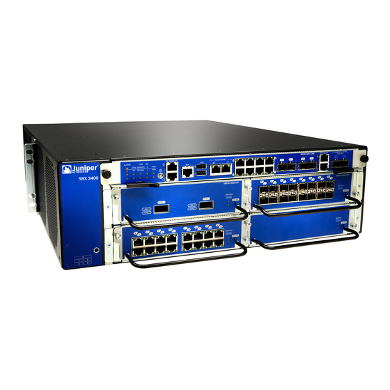
- Page 9 Figure 1: SRX3400 Services Gateway ........
- Page 10 Unpacking the Services Gateway ........131 Figure 43: Unpacking the SRX3400 Services Gateway ..... 132 Chapter 17 Installing the Mounting Hardware .
- Page 11 List of Figures Figure 54: Installing the SCM in the SRX3400 Services Gateway ... . 152 Figure 55: Identifying Power Supply Types ......153 Figure 56: Installing an AC Power Supply .
- Page 12 SRX3400 Services Gateway Hardware Figure 89: SRX3400 Services Gateway Chassis Serial Number Label ..235 Figure 90: SFB Serial Number Label ........236 Figure 91: AC Power Supply Serial Number Label .
- Page 13 Introduction ............3 Table 3: Summary of SRX3400 Services Gateway Features ....4 Chapter 2 Hardware Specifications .
- Page 14 Unpacking the Services Gateway ........131 Table 32: Parts List for a Fully Configured SRX3400 Services Gateway ..133 Table 33: Accessory Box Parts List .
-
Page 15: About The Documentation
® To obtain the most current version of all Juniper Networks technical documentation, see the product documentation page on the Juniper Networks website at http://www.juniper.net/techpubs/ If the information in the latest release notes differs from the information in the documentation, follow the product Release Notes. -
Page 16: Table 1: Notice Icons
[edit protocols directories; configuration hierarchy levels; hierarchy level. ospf area area-id] or labels on routing platform The console port is labeled CONSOLE components. < > (angle brackets) Enclose optional keywords or variables. stub <default-metric metric>; Copyright © 2013, Juniper Networks, Inc. -
Page 17: Documentation Feedback
Software release version (if applicable) Requesting Technical Support Technical product support is available through the Juniper Networks Technical Assistance Center (JTAC). If you are a customer with an active J-Care or JNASC support contract, Copyright © 2013, Juniper Networks, Inc. -
Page 18: Self-Help Online Tools And Resources
7 days a week, 365 days a year. Self-Help Online Tools and Resources For quick and easy problem resolution, Juniper Networks has designed an online self-service portal called the Customer Support Center (CSC) that provides you with the following features: Find CSC offerings: http://www.juniper.net/customers/support/... -
Page 19: Overview
PART 1 Overview Introduction on page 3 Hardware Specifications on page 7 Power Supply Specifications on page 11 Hardware Components on page 19 Modules Supported On SRX1400, SRX3400, and SRX3600 Services Gateways on page 41 Copyright © 2013, Juniper Networks, Inc. - Page 20 SRX3400 Services Gateway Hardware Copyright © 2013, Juniper Networks, Inc.
-
Page 21: Introduction
SRX3400 Services Gateway Performance and Features on page 4 Employing the SRX3400 Services Gateway For Your Enterprise Gateway on page 4 Employing the SRX3400 Services Gateway in Your Enterprise Data Center on page 5 Employing the SRX3400 Services Gateway in the Service Provider Network on page 5... -
Page 22: Srx3400 Services Gateway Performance And Features
IPsec VPN tunnel termination. Application Layer security, including high-speed intrusion protection. Related Employing the SRX3400 Services Gateway in Your Enterprise Data Center on page 5 Documentation Employing the SRX3400 Services Gateway in the Service Provider Network on page 5 SRX3400 Services Gateway Description on page 3... -
Page 23: Employing The Srx3400 Services Gateway In Your Enterprise Data Center
Employing the SRX3400 Services Gateway For Your Enterprise Gateway on page 4 Documentation Employing the SRX3400 Services Gateway in the Service Provider Network on page 5 SRX3400 Services Gateway Description on page 3 Employing the SRX3400 Services Gateway in the Service Provider Network The Service Provider (SP) provides secure hosting and network services at the SP. - Page 24 SRX3400 Services Gateway Hardware Copyright © 2013, Juniper Networks, Inc.
-
Page 25: Hardware Specifications
SRX3400 Services Gateway Environmental Specifications on page 8 SRX3400 Services Gateway Grounding-Cable Lug Specification on page 9 SRX3400 Services Gateway Grounding Cable Specification on page 9 Console Port Cable and Wire Specifications for the SRX3400 Services Gateway on page 10 SRX3400 Services Gateway Physical Specifications... -
Page 26: Srx3400 Services Gateway Environmental Specifications
Related Available Components for the SRX3400 Services Gateway on page 19 Documentation Hardware Component Locations in the SRX3400 Services Gateway Chassis on page 21 SRX3400 Services Gateway Chassis on page 23 SRX3400 Services Gateway Environmental Specifications Table 5 on page 8 specifies the environmental specifications required for normal services gateway operation. -
Page 27: Srx3400 Services Gateway Grounding-Cable Lug Specification
Related SRX3400 Services Gateway Agency Approvals on page 107 Documentation SRX3400 Services Gateway General Safety Guidelines and Warnings on page 85 SRX3400 Services Gateway Fire Safety Requirements and Fire Suppression Equipment on page 87 SRX3400 Services Gateway Definition of Safety Warning Levels on page 83... -
Page 28: Table 6: Cable And Wire Specifications For Routing Engine Management And Alarm Interfaces
RJ-45/DB-9 connectors Related Connecting the SRX3400 Services Gateway to a Management Console or an Auxiliary Documentation Device on page 166 SRX3400 Services Gateway Switch Fabric Board on page 26 SRX3400 Services Gateway Routing Engine on page 35... -
Page 29: Power Supply Specifications
CHAPTER 3 Power Supply Specifications SRX3400 Services Gateway AC Power Supply Electrical Specifications on page 11 SRX3400 Services Gateway AC Power System Electrical Specifications on page 12 SRX3400 Services Gateway AC Power Cord Specifications on page 13 SRX3400 Services Gateway DC Power Supply Electrical Specifications on page 15... -
Page 30: Srx3400 Services Gateway Ac Power System Electrical Specifications
Related SRX3400 Services Gateway Chassis on page 23 Documentation Hardware Component Locations in the SRX3400 Services Gateway Chassis on page 21 SRX3400 Services Gateway AC Power Supply Overview on page 37 SRX3400 Services Gateway AC Power System Electrical Specifications Table 9 on page 12 lists the AC power system electrical specifications. -
Page 31: Srx3400 Services Gateway Ac Power Cord Specifications
Chapter 3: Power Supply Specifications SRX3400 Services Gateway AC Power Cord Specifications Each AC power supply has a single AC appliance inlet located on the power supply that requires a dedicated AC power feed and a dedicated 15 A (250 VAC) circuit breaker. Most... -
Page 32: Figure 3: Ac Plug Types
167. For instructions on replacing the AC power cables, see “Replacing AC Power Supply Cables on the SRX3400 Services Gateway” on page 210. Related SRX3400 Services Gateway AC Power System Electrical Specifications on page 12 Documentation Copyright © 2013, Juniper Networks, Inc. -
Page 33: Srx3400 Services Gateway Dc Power Supply Electrical Specifications
Chapter 3: Power Supply Specifications SRX3400 Services Gateway AC Power Supply Electrical Specifications Power Requirements for AC-Powered SRX3400 Services Gateways on page 71 SRX3400 Services Gateway DC Power Supply Electrical Specifications Two types of DC power supply are available. The standard DC power supply has a maximum power output of 850 W. -
Page 34: Srx3400 Services Gateway Dc Power System Electrical Specifications
Related SRX3400 Services Gateway Chassis on page 23 Documentation Hardware Component Locations in the SRX3400 Services Gateway Chassis on page 21 SRX3400 Services Gateway DC Power Supply Overview on page 37 SRX3400 Services Gateway DC Power System Electrical Specifications Table 13 on page 16 lists the DC power system electrical specifications. -
Page 35: Figure 4: Typical Dc Source Cabling To The Srx3400 Services Gateway
“Connecting the SRX3400 Services Gateway to a DC Power Source” on page 169. For instructions on replacing a DC power cable, see “Replacing DC Power Supply Cables on the SRX3400 Services Gateway” on page 215. Copyright © 2013, Juniper Networks, Inc. -
Page 36: Table 14: Dc Power Cable Specifications
), minimum 60°C wire, or as permitted by the local code Related SRX3400 Services Gateway DC Power System Electrical Specifications on page 16 Documentation SRX3400 Services Gateway DC Power Supply Electrical Specifications on page 15 Power Requirements for DC-Powered SRX3400 Services Gateways on page 73... -
Page 37: Hardware Components
CHAPTER 4 Hardware Components Available Components for the SRX3400 Services Gateway on page 19 Hardware Component Locations in the SRX3400 Services Gateway Chassis on page 21 SRX3400 Services Gateway Chassis on page 23 SRX3400 Services Gateway CFMs on page 24... - Page 38 SRX3400 Services Gateway Hardware Table 15: Available SRX3400 Services Gateway Hardware Components (continued) Hardware Component Minimum/Maximum Network Processing I/O Cards (NP-IOCs) Up to 6 allowed (see note below) Network Processing Cards (NPCs) 1 required, 2 allowed Services Processing Cards (SPCs)
-
Page 39: Hardware Component Locations In The Srx3400 Services Gateway Chassis
Table 16 on page 21 shows the supported combinations of SPCs, NPCs, and IOCs that can be installed in the SRX3400 Services Gateway. The support is different between standard and enhanced DC-powered services gateways because the standard DC power supplies have a lower power rating. -
Page 40: Figure 5: Front Slots On The Srx3400 Services Gateway
SRX3400 Services Gateway Hardware Table 17: Allowed Slot Locations for the SRX3400 Services Gateway Components Module Name Allowed Slot Locations Front slot labeled Routing Engine Rear slot labeled Rear slot labeled IOCs Front slots labeled NP-IOCs Front slots labeled and rear slots labeled . -
Page 41: Srx3400 Services Gateway Chassis
Documentation Available Components for the SRX3400 Services Gateway on page 19 Installing CFM Cards in the SRX3400 Services Gateway on page 145 Data Flow in the SRX3400 Services Gateway on page 25 Installation Overview for the SRX3400 Services Gateway on page 137... -
Page 42: Srx3400 Services Gateway Cfms
Documentation SRX3400 Services Gateway Description on page 3 Hardware Component Locations in the SRX3400 Services Gateway Chassis on page 21 Available Components for the SRX3400 Services Gateway on page 19 Data Flow in the SRX3400 Services Gateway on page 25... -
Page 43: Data Flow In The Srx3400 Services Gateway
Installation Overview for the SRX3400 Services Gateway on page 137 SRX3400 Services Gateway Midplane The midplane in the SRX3400 Services Gateway is in the center of the chassis and provides connections for installing up to four common form-factor modules (CFMs) through the front of the chassis and up to three CFMs through the rear of the chassis. -
Page 44: Srx3400 Services Gateway Switch Fabric Board
Related SRX3400 Services Gateway Chassis on page 23 Documentation Available Components for the SRX3400 Services Gateway on page 19 SRX3400 Services Gateway Switch Fabric Board on page 26 SRX3400 Services Gateway NPCs on page 32 SRX3400 Services Gateway SPCs on page 32 SRX3400 Services Gateway Switch Fabric Board The Switch Fabric Board (SFB) is the data plane for the subsystems in the chassis. -
Page 45: Table 19: Switch Fabric Board Led Indicators
A critical alarm is present in the system. A hardware (Bottom) component or software module has failed, or the network management interface is down. Dark No critical alarms are present in the system. (unlit) SFB and HA (pair) Copyright © 2013, Juniper Networks, Inc. - Page 46 The SFB or one or more of the installed CFM cards has failed. The LEDs on the failed CFM SERVICE cards are red. Dark One or more of the installed CFM cards are disabled. (unlit) SERVICE LEDs on the disabled CFM cards are dark. Copyright © 2013, Juniper Networks, Inc.
- Page 47 The Routing Engine in slot RE0 is initializing. On steadily Either the Routing Engine or Control Board function on RE0 has failed and is not operating normally. Dark The RE0 slot is empty. (unlit) Unused. (bottom) Power and Fan (pair) Copyright © 2013, Juniper Networks, Inc.
-
Page 48: Table 20: Switch Fabric Board Front Panel Ports And Connectors
Unused. (top), Universal serial bus connectors that can be managed and USB0 accessed by the master Routing Engine. USB1 (bottom) RJ-45 port used to manage the Routing Engine in slot RE0. RE ETHERNET 0 Copyright © 2013, Juniper Networks, Inc. - Page 49 Related SRX3400 Services Gateway Chassis on page 23 Documentation Available Components for the SRX3400 Services Gateway on page 19 SRX3400 Services Gateway NPCs on page 32 SRX3400 Services Gateway SPCs on page 32 SRX3400 Services Gateway NP-IOCs on page 34...
-
Page 50: Srx3400 Services Gateway Npcs
Related SRX3400 Services Gateway Chassis on page 23 Documentation Installing CFM Cards in the SRX3400 Services Gateway on page 145 Available Components for the SRX3400 Services Gateway on page 19 SRX3400 Services Gateway Switch Fabric Board on page 26 SRX3400 Services Gateway SPCs on page 32... -
Page 51: Srx3400 Services Gateway Iocs
Network Processing Card (NPC) and to forward data packets out the physical ports after services processing. The SRX3400 Services Gateway has four slots in the front of the chassis where you can install IOCs. You can install any combination of IOCs in the slots. -
Page 52: Srx3400 Services Gateway Np-Iocs
Related SRX3400 Services Gateway Chassis on page 23 Documentation Installing CFM Cards in the SRX3400 Services Gateway on page 145 Available Components for the SRX3400 Services Gateway on page 19 SRX3400 Services Gateway Switch Fabric Board on page 26 SRX3400 Services Gateway NPCs on page 32... -
Page 53: Srx3400 Services Gateway Routing Engine
Related SRX3400 Services Gateway Chassis on page 23 Documentation Installing CFM Cards in the SRX3400 Services Gateway on page 145 Available Components for the SRX3400 Services Gateway on page 19 SRX3400 Services Gateway Switch Fabric Board on page 26 SRX3400 Services Gateway NPCs on page 32... -
Page 54: Srx3400 Services Gateway Srx Clustering Module
Documentation Available Components for the SRX3400 Services Gateway on page 19 Hardware Component Locations in the SRX3400 Services Gateway Chassis on page 21 SRX3400 Services Gateway SRX Clustering Module The SRX Clustering Module (SCM) is a card that you can install in the services gateway to enable the dual control link feature for chassis cluster supported in Junos OS Release 10.2 and later. -
Page 55: Srx3400 Services Gateway Ac Power Supply Overview
Documentation SRX3400 Services Gateway AC Power Supply Overview In an AC power configuration, the SRX3400 Services Gateway contains one or two AC power supplies, located at the rear of the chassis in slots PEM0 and PEM1. Each power supply provides power to all components in the services gateway. When two power supplies are present, they share power almost equally within a fully populated system. -
Page 56: Srx3400 Services Gateway Fan Tray
Hardware Component Locations in the SRX3400 Services Gateway Chassis on page 21 SRX3400 Services Gateway DC Power Supply Electrical Specifications on page 15 Installing a DC Power Supply in the SRX3400 Services Gateway on page 155 SRX3400 Services Gateway Fan Tray The cooling system consists of a fan tray containing four fans and an air filter. -
Page 57: Figure 19: Fan Tray
The fans have three speeds: low, intermediate, and high. Table 21 on page 40 shows the correlations between fan speed and critical component temperature. Note that there is Copyright © 2013, Juniper Networks, Inc. -
Page 58: Table 21: Critical Component Temperatures And Fan Speed Transitions
Related SRX3400 Services Gateway Chassis on page 23 Documentation Hardware Component Locations in the SRX3400 Services Gateway Chassis on page 21 Available Components for the SRX3400 Services Gateway on page 19 Copyright © 2013, Juniper Networks, Inc. -
Page 59: Modules Supported On Srx1400, Srx3400, And Srx3600 Services
SRX1400, SRX3400, and SRX3600 Services Gateway Module Overview The modules described in this guide let you upgrade and customize your SRX1400, SRX3400, or SRX3600 Services Gateway to suit the needs of your network. The following types of modules are available for the SRX1400, SRX3400, and SRX3600 Services Gateways: Copyright ©... -
Page 60: Modules Supported On Srx1400, Srx3400, And Srx3600 Services
Related Modules Supported on SRX1400, SRX3400, and SRX3600 Services Gateways on Documentation page 43 Eligible Slots for SRX1400, SRX3400, and SRX3600 Services Gateway Modules on page 44 Installing Common Form Factor Modules In SRX1400, SRX3400, and SRX3600 Services Gateways Copyright © 2013, Juniper Networks, Inc. -
Page 61: Gateways
Chapter 5: Modules Supported On SRX1400, SRX3400, and SRX3600 Services Gateways Modules Supported on SRX1400, SRX3400, and SRX3600 Services Gateways Table 22 on page 43 describes the modules supported on the SRX1400, SRX3400, and SRX3600 Services Gateways. Table 22: Supported Modules for SRX1400, SRX3400, and SRX3600 Services Gateways... -
Page 62: Table 23: Supported Slots For Srx1400, Srx3400, And Srx3600 Services Gateway Modules
Table 23 on page 44 summarizes the slots in which you can install each module type for SRX1400, SRX3400, and SRX3600 Services Gateways. Table 23: Supported Slots for SRX1400, SRX3400, and SRX3600 Services Gateway Modules Supported Slots Module Name and Number... -
Page 63: Hot-Swappable And Cold-Swap-Only Modules On The Srx1400, Srx3400, And Srx3600 Services Gateways
SRX3400, CFM slots through in the SRX3600). When an SRX3400 or SRX3600 Services Gateway is in the services offload mode supported in Junos OS release 12.1X44-D10 and later, IOCs are only supported in front panel slots through . -
Page 64: Services Processing Card Srx3K-Spc-1-10-40
NOTE: For the SRX3400 Services Gateway to meet NEBS and ETSI standards, it must not have any two SPCs installed side by side in the CFM slots in the front of the chassis (CFM slots through ). -
Page 65: Network Processing Card Srx3K-Npc
Chapter 5: Modules Supported On SRX1400, SRX3400, and SRX3600 Services Gateways LEDs SERVICE LED, one tricolor Green–The SPC is running under acceptable load. Amber–The SPC is overloaded. Red–No service is being provided by the SPC. Off–The SPC is not enabled. -
Page 66: Figure 23: Network Processing Card Srx3K-Npc
SRX3400 Services Gateway Hardware Figure 23: Network Processing Card SRX3K-NPC SR X3K -NP Description NPC for SRX3400, SRX3600, and SRX1400 Power requirement: 64 W maximum Weight: 2.2 lb (1.0 kg) Software release Junos OS Release 9.3 and later Cables and connectors... -
Page 67: I/O Card Srx3K-16Ge-Tx
(except as noted below) NOTE: When an SRX3400 or SRX3600 Services Gateway is in the services offload mode supported in Junos OS release 12.1X44-D10 and later, IOCs are only supported in front panel slots through . See the Junos OS documentation for more information about services offload mode. -
Page 68: I/O Card Srx3K-16Ge-Sfp
IOCs Similar) Serial number label Related SRX1400, SRX3400, and SRX3600 Services Gateway Module Overview on page 41 Documentation Modules Supported on SRX1400, SRX3400, and SRX3600 Services Gateways on page 43 Eligible Slots for SRX1400, SRX3400, and SRX3600 Services Gateway Modules on... -
Page 69: Figure 27: 16-Port Sfp Gigabit Ethernet Ioc
(except as noted below) NOTE: When an SRX3400 or SRX3600 Services Gateway is in the services offload mode supported in Junos OS release 12.1X44-D10 and later, IOCs are only supported in front panel slots through . See the Junos OS documentation for more information about services offload mode. -
Page 70: I/O Card Srx3K-2Xge-Xfp
IOCs Similar) Serial number label Related SRX1400, SRX3400, and SRX3600 Services Gateway Module Overview on page 41 Documentation Modules Supported on SRX1400, SRX3400, and SRX3600 Services Gateways on page 43 Eligible Slots for SRX1400, SRX3400, and SRX3600 Services Gateway Modules on... - Page 71 (except as noted below) NOTE: When an SRX3400 or SRX3600 Services Gateway is in the services offload mode supported in Junos OS release 12.1X44-D10 and later, IOCs are only supported in front panel slots through . See the Junos OS documentation for more information about services offload mode.
-
Page 72: Network Processing I/O Card Srx1K3K-Np-2Xge-Sfpp
NP-IOC online after you insert it or offline before ONLINE you remove it. Description 2-port Ethernet SFP+ NP-IOC for SRX3400, SRX3600, and SRX1400 Services Gateways Power requirement: 52 W maximum Weight: 2.4 lb (1.1 kg) Maximum configurable MTU: 9192 bytes Software release Junos OS Release 12.1X44-D10 and later... -
Page 73: Routing Engines Srx3K-Re-12-10 And Srx1K-Re-12-10
Chapter 5: Modules Supported On SRX1400, SRX3400, and SRX3600 Services Gateways LEDs SERVICE LED, one bicolor Off–The NP-IOC is administratively disabled. Green–The NP-IOC is available to carry Ethernet traffic. Amber–The NP-IOC is not available to carry Ethernet traffic. LED, one bicolor OK/FAIL Off–One or more of the following conditions apply:... -
Page 74: Figure 33: Routing Engine
Figure 33: Routing Engine (SRX3K-RE-12-10 Shown, SRX1K-RE-12-10 Similar) Description Routing Engine for SRX1400 Services Gateway (SRX1K-RE-12-10) Routing Engine for SRX3400 or SRX3600 Services Gateway (SRX3K-RE-12-10) Power requirement: 53 W maximum Weight: 2.9 lb (1.3 kg) Software release SRX3K-RE-12-10: Junos OS Release 9.3 and later SRX1K-RE-12-10: Junos OS Release 10.2 and later... -
Page 75: Figure 34: Routing Engine Serial Number Label
Chapter 5: Modules Supported On SRX1400, SRX3400, and SRX3600 Services Gateways LEDs OK/FAIL LED, one bicolor Off–One or more of the following conditions apply: The services gateway is not powered on. The services gateway is still in the process of either booting or shutting down. -
Page 76: Srx Clustering Module Srx3K-Crm
SRX3400 Services Gateway Hardware SRX Clustering Module SRX3K-CRM The SRX Clustering Module (SCM) is a card that you can install in the SRX3400 and SRX3600 Services Gateway to enable the dual control link feature for chassis cluster supported in Junos OS Release 10.2 and later (Figure 16 on page 36). -
Page 77: Figure 36: Scm Serial Number Label
Chapter 5: Modules Supported On SRX1400, SRX3400, and SRX3600 Services Gateways Serial Number The serial number label is located as shown in Figure 36 on page 59). Location Figure 36: SCM Serial Number Label Serial number label Related SRX1400, SRX3400, and SRX3600 Services Gateway Module Overview on page 41... - Page 78 SRX3400 Services Gateway Hardware Copyright © 2013, Juniper Networks, Inc.
-
Page 79: Planning
PART 2 Planning Preparing the Site for Installation on page 63 Cabinet and Rack Requirements on page 65 Power Requirements on page 71 Cable and Electrical Wiring Guidelines on page 75 Copyright © 2013, Juniper Networks, Inc. - Page 80 SRX3400 Services Gateway Hardware Copyright © 2013, Juniper Networks, Inc.
-
Page 81: Preparing The Site For Installation
CHAPTER 6 Preparing the Site for Installation Site Preparation Checklist for the SRX3400 Services Gateway on page 63 Site Preparation Checklist for the SRX3400 Services Gateway The checklist in Table 25 on page 63 summarizes the tasks you need to perform when preparing a site for SRX3400 Services Gateway installation. - Page 82 SRX3400 Services Gateway Hardware Copyright © 2013, Juniper Networks, Inc.
-
Page 83: Cabinet And Rack Requirements
SRX3400 Services Gateway Rack Size and Strength Requirements on page 66 SRX3400 Services Gateway Spacing of Mounting Bracket Holes on page 68 Connecting the SRX3400 Services Gateway to the Building Structure on page 68 Clearance Requirements for Airflow and Hardware Maintenance of the SRX3400... -
Page 84: Srx3400 Services Gateway Cabinet Airflow Requirements
Clearance Requirements for Airflow and Hardware Maintenance of the SRX3400 Services Gateway on page 68 SRX3400 Services Gateway Cabinet Size and Clearance Requirements on page 65 SRX3400 Services Gateway Rack Size and Strength Requirements on page 66 SRX3400 Services Gateway Spacing of Mounting Bracket Holes on page 68 SRX3400 Services Gateway Rack Size and Strength Requirements The services gateway is designed for installation into a 19 in. -
Page 85: Figure 37: Typical Open-Frame Rack
Cabinets, Racks, Panels, and Associated Equipment (document number EIA-310-D) published by the Electronics Industry Association. You can stack eight SRX3400 Services Gateways in a rack that has at least 40 U (70 in. or 1.78 m) of usable vertical space. -
Page 86: Srx3400 Services Gateway Spacing Of Mounting Bracket Holes
Clearance Requirements for Airflow and Hardware Maintenance of the SRX3400 Services Gateway on page 68 Connecting the SRX3400 Services Gateway to the Building Structure on page 68 Connecting the SRX3400 Services Gateway to the Building Structure Always secure the rack to the structure of the building. If your geographical area is subject to earthquakes, bolt the rack to the floor. -
Page 87: Figure 38: Clearance Requirements
SRX3400 Services Gateway Rack Size and Strength Requirements on page 66 Documentation Connecting the SRX3400 Services Gateway to the Building Structure on page 68 SRX3400 Services Gateway Spacing of Mounting Bracket Holes on page 68 Copyright © 2013, Juniper Networks, Inc. - Page 88 SRX3400 Services Gateway Hardware Copyright © 2013, Juniper Networks, Inc.
-
Page 89: Power Requirements
CHAPTER 8 Power Requirements Power Requirements for AC-Powered SRX3400 Services Gateways on page 71 Power Requirements for DC-Powered SRX3400 Services Gateways on page 73 Power Requirements for AC-Powered SRX3400 Services Gateways NOTE: If you plan to operate a maximally configured AC-powered services gateway, we recommend that you provision 6 A @ 240 VAC (or 14 A @ 100 VAC) for the system. -
Page 90: Table 27: Component Ac Power Requirements
Watts * 3.41 = BTU/hr 1079 W * 3.41 = 3679 BTU/hr Related SRX3400 Services Gateway AC Power System Electrical Specifications on page 12 Documentation SRX3400 Services Gateway AC Power Supply Electrical Specifications SRX3400 Services Gateway AC Power Cord Specifications on page 13... -
Page 91: Power Requirements For Dc-Powered Srx3400 Services Gateways
Chapter 8: Power Requirements Power Requirements for DC-Powered SRX3400 Services Gateways NOTE: If you plan to operate a maximally configured DC-powered services gateway, we recommend that you provision 30 A @ -48 VDC for the system. If you do not plan to provision 30 A @ -48 VDC for the system, you can use the information... - Page 92 Watts DC * 3.41 = BTU/hr 1004 * 3.41 = 3424 BTU/hr Related SRX3400 Services Gateway DC Power System Electrical Specifications on page 16 Documentation SRX3400 Services Gateway DC Power Supply Electrical Specifications on page 15 SRX3400 Services Gateway DC Power Cable Specifications on page 16...
-
Page 93: Cable And Electrical Wiring Guidelines
CHAPTER 9 Cable and Electrical Wiring Guidelines Distance Limitations for Signaling for the SRX3400 Services Gateway on page 75 Radio Frequency Interference for the SRX3400 Services Gateway on page 75 Electromagnetic Compatibility for the SRX3400 Services Gateway on page 76... -
Page 94: Electromagnetic Compatibility For The Srx3400 Services Gateway
Related Distance Limitations for Signaling for the SRX3400 Services Gateway on page 75 Documentation Radio Frequency Interference for the SRX3400 Services Gateway on page 75... -
Page 95: Gateway
(including those from dispersion), and a safety margin for unexpected losses. Related Signal Loss in Multimode and Single-Mode Fiber-Optic Cable for the SRX3400 Services Documentation Gateway on page 76 Calculating the Power Budget for Fiber-Optic Cable for the SRX3400 Services Gateway... -
Page 96: Gateway
– P = –15 dBm – (–28 dBm) = 13 dB Related Signal Loss in Multimode and Single-Mode Fiber-Optic Cable for the SRX3400 Services Documentation Gateway on page 76 Attenuation and Dispersion in Fiber-Optic Cable for the SRX3400 Services Gateway... - Page 97 In both examples, the calculated power margin is greater than zero, indicating that the link has sufficient power for transmission and does not exceed the maximum receiver input power. Related Signal Loss in Multimode and Single-Mode Fiber-Optic Cable for the SRX3400 Services Documentation Gateway on page 76 Copyright © 2013, Juniper Networks, Inc.
- Page 98 SRX3400 Services Gateway Hardware Attenuation and Dispersion in Fiber-Optic Cable for the SRX3400 Services Gateway on page 77 Calculating the Power Budget for Fiber-Optic Cable for the SRX3400 Services Gateway on page 77 Copyright © 2013, Juniper Networks, Inc.
-
Page 99: Part 3 Safety
Installation Safety Guidelines and Warnings on page 89 Maintenance and Operation Warnings on page 97 Agency Approval and Compliance Statements on page 107 Laser and LED Safety Guidelines and Warnings on page 113 Electrical Safety Guidelines and Warnings on page 117 Copyright © 2013, Juniper Networks, Inc. - Page 100 SRX3400 Services Gateway Hardware Copyright © 2013, Juniper Networks, Inc.
-
Page 101: Safety And Regulatory Warnings
CHAPTER 10 Safety And Regulatory Warnings SRX3400 Services Gateway Safety Requirements, Warnings, and Guidelines on page 83 SRX3400 Services Gateway Definition of Safety Warning Levels on page 83 SRX3400 Services Gateway General Safety Guidelines and Warnings on page 85 Preventing Electrostatic Discharge Damage to the SRX3400 Services... - Page 102 ¡Atención! Este símbolo de aviso significa peligro. Existe riesgo para su integridad física. Antes de manipular cualquier equipo, considerar los riesgos Copyright © 2013, Juniper Networks, Inc.
-
Page 103: Srx3400 Services Gateway General Safety Guidelines And Warnings
Related SRX3400 Services Gateway General Safety Guidelines and Warnings on page 85 Documentation Preventing Electrostatic Discharge Damage to the SRX3400 Services Gateway on... -
Page 104: Gateway
Avoid touching uninsulated electrical wires or terminals that have not been disconnected from their power source. Such an action could cause electrical shock. Related SRX3400 Services Gateway Definition of Safety Warning Levels on page 83 Documentation Preventing Electrostatic Discharge Damage to the SRX3400 Services Gateway on... -
Page 105: Equipment
Figure 41: Placing a Component into an Electrostatic Bag Related SRX3400 Services Gateway General Safety Guidelines and Warnings on page 85 Documentation SRX3400 Services Gateway Definition of Safety Warning Levels on page 83 SRX3400 Services Gateway Fire Safety Requirements and Fire Suppression Equipment... -
Page 106: Equipment
To keep warranties effective, do not use a dry chemical fire extinguisher to control a fire at or near a Juniper Networks services gateway. If a dry chemical fire extinguisher is used, the unit is no longer eligible for coverage under a service agreement. -
Page 107: Installation Safety Guidelines And Warnings
(CFMs). The handles might break off and cause the chassis to fall and inflict injury. Related SRX3400 Services Gateway General Safety Guidelines and Warnings on page 85 Documentation Installation Instructions Warning on page 90 Rack-Mounting Requirements and Warnings on page 90 Ramp Warning on page 94 Copyright ©... -
Page 108: Installation Instructions Warning
Varning! Läs installationsanvisningarna innan du kopplar systemet till dess strömförsörjningsenhet. Related SRX3400 Services Gateway General Safety Guidelines and Warnings on page 85 Documentation Chassis Lifting Guidelines on page 89 Rack-Mounting Requirements and Warnings on page 90... - Page 109 De onderstaande richtlijnen worden verstrekt om uw veiligheid te verzekeren: De Juniper Networks services gateway moet in een stellage worden geïnstalleerd die aan een bouwsel is verankerd. Dit toestel dient onderaan in het rek gemonteerd te worden als het toestel het enige in het rek is.
- Page 110 SRX3400 Services Gateway Hardware Le rack sur lequel est monté le Juniper Networks services gateway doit être fixé à la structure du bâtiment. Si cette unité constitue la seule unité montée en casier, elle doit être placée dans le bas.
- Page 111 Chapter 11: Installation Safety Guidelines and Warnings Juniper Networks services gateway må installeres i et stativ som er forankret til bygningsstrukturen. Denne enheten bør monteres nederst i kabinettet hvis dette er den eneste enheten i kabinettet. Ved montering av denne enheten i et kabinett som er delvis fylt, skal kabinettet lastes fra bunnen og opp med den tyngste komponenten nederst i kabinettet.
-
Page 112: Ramp Warning
Om ställningen är försedd med stabiliseringsdon skall dessa monteras fast innan enheten installeras eller underhålls på ställningen. Related SRX3400 Services Gateway General Safety Guidelines and Warnings on page 85 Documentation Chassis Lifting Guidelines on page 89 Installation Instructions Warning on page 90... - Page 113 Chapter 11: Installation Safety Guidelines and Warnings Installation Instructions Warning on page 90 Rack-Mounting Requirements and Warnings on page 90 Copyright © 2013, Juniper Networks, Inc.
- Page 114 SRX3400 Services Gateway Hardware Copyright © 2013, Juniper Networks, Inc.
-
Page 115: Maintenance And Operation Warnings
Aviso Este equipamento deverá ser instalado ou substituído apenas por pessoal devidamente treinado e qualificado. ¡Atención! Estos equipos deben ser instalados y reemplazados exclusivamente por personal técnico adecuadamente preparado y capacitado. Copyright © 2013, Juniper Networks, Inc. -
Page 116: Restricted Access Area Warning
Restricted Access Area Warning on page 98 Documentation SRX3400 Services Gateway General Safety Guidelines and Warnings on page 85 SRX3400 Services Gateway Definition of Safety Warning Levels on page 83 Preventing Electrostatic Discharge Damage to the SRX3400 Services Gateway on... -
Page 117: Battery Handling Warning
Related Qualified Personnel Warning on page 97 Documentation SRX3400 Services Gateway General Safety Guidelines and Warnings on page 85 SRX3400 Services Gateway Definition of Safety Warning Levels on page 83 Preventing Electrostatic Discharge Damage to the SRX3400 Services Gateway on... - Page 118 Följ tillverkarens anvisningar vid kassering av använda batterier. Related Jewelry Removal Warning on page 101 Documentation Lightning Activity Warning on page 102 Operating Temperature Warning on page 103 Product Disposal Warning on page 104 Copyright © 2013, Juniper Networks, Inc.
-
Page 119: Jewelry Removal Warning
à terra, podendo causar queimaduras graves ou ficarem soldados aos terminais. ¡Atención! Antes de operar sobre equipos conectados a líneas de alimentación, quitarse las joyas (incluidos anillos, collares y relojes). Los Copyright © 2013, Juniper Networks, Inc. -
Page 120: Lightning Activity Warning
¡Atención! No operar el sistema ni conectar o desconectar cables durante el transcurso de descargas eléctricas en la atmósfera. Varning! Vid åska skall du aldrig utföra arbete på systemet eller ansluta eller koppla loss kablar. Copyright © 2013, Juniper Networks, Inc. -
Page 121: Operating Temperature Warning
104°F (40°C). To prevent airflow restriction, allow at least 6 in. (15.2 cm) of clearance around the ventilation openings. Waarschuwing Om te voorkomen dat welke services gateway van de Juniper Networks services gateway dan ook oververhit raakt, dient u deze niet te bedienen op een plaats waar de maximale aanbevolen omgevingstemperatuur van 40°C wordt overschreden. -
Page 122: Product Disposal Warning
15,2 cm à volta das aberturas de ventilação. ¡Atención! Para impedir que un encaminador de la serie Juniper Networks services gateway se recaliente, no lo haga funcionar en un área en la que se supere la temperatura ambiente máxima recomendada de 40°C. - Page 123 Varning! Slutlig kassering av denna produkt bör skötas i enlighet med landets alla lagar och föreskrifter. Related Battery Handling Warning on page 99 Documentation Jewelry Removal Warning on page 101 Lightning Activity Warning on page 102 Operating Temperature Warning on page 103 Copyright © 2013, Juniper Networks, Inc.
- Page 124 SRX3400 Services Gateway Hardware Copyright © 2013, Juniper Networks, Inc.
-
Page 125: Agency Approval And Compliance Statements
Agency Approval and Compliance Statements SRX3400 Services Gateway Agency Approvals on page 107 SRX3400 Services Gateway Compliance Statements for EMC Requirements on page 108 SRX3400 Services Gateway NEBS and ETSI Compliance on page 109 SRX3400 Services Gateway Agency Approvals The services gateway complies with the following standards:... -
Page 126: Srx3400 Services Gateway Compliance Statements For Emc Requirements
Documentation General Electrical Safety Guidelines and Warnings on page 117 DC Power Electrical Safety Guidelines and Warnings on page 122 SRX3400 Services Gateway Compliance Statements for EMC Requirements This section includes the following topics: Canada on page 108 European Community on page 108... -
Page 127: Japan
SRX3400 Services Gateway NEBS and ETSI Configuration Requirements on page 110 SRX3400 Services Gateway NEBS and ETSI Standards The SRX3400 Services Gateway, when it is installed and configured as described in this section, meets the following NEBS and ETSI standards:... -
Page 128: Requirements
ETSI 300019-2-1 ETSI 300019-2-2 ETSI 300019-2-3 GR-1089-CORE SRX3400 Services Gateway NEBS and ETSI Configuration Requirements To meet the NEBS and ETSI standards described in “SRX3400 Services Gateway NEBS and ETSI Standards” on page 109, the SRX3400 Services Gateway must be configured... -
Page 129: Table 31: Extended Temperature Sfp, Sfp+, And Xfp Transceivers
10GBASE-ER SFP+ optical transceiver SRX-SFP-10GE-LR 10GBASE-LR SFP+ optical transceiver Related SRX3400 Services Gateway Agency Approvals on page 107 Documentation In Case of Electrical Accident on page 117 General Electrical Safety Guidelines and Warnings on page 117 DC Power Electrical Safety Guidelines and Warnings on page 122... - Page 130 SRX3400 Services Gateway Hardware Copyright © 2013, Juniper Networks, Inc.
-
Page 131: Laser And Led Safety Guidelines And Warnings
Related Class 1 Laser Product Warning on page 114 Documentation Class 1 LED Product Warning on page 114 Laser Beam Warning on page 115 Radiation from Open Port Apertures Warning on page 116 Copyright © 2013, Juniper Networks, Inc. -
Page 132: Class 1 Laser Product Warning
Attention Alarme de produit LED Class I. Warnung Class 1 LED-Produktwarnung. Avvertenza Avvertenza prodotto LED di Classe 1. Advarsel LED-produkt i klasse 1. Aviso Produto de classe 1 com LED. ¡Atención! Aviso sobre producto LED de Clase 1. Copyright © 2013, Juniper Networks, Inc. -
Page 133: Laser Beam Warning
Related General Laser Safety Guidelines on page 113 Documentation Class 1 Laser Product Warning on page 114 Class 1 LED Product Warning on page 114 Radiation from Open Port Apertures Warning on page 116 Copyright © 2013, Juniper Networks, Inc. -
Page 134: Radiation From Open Port Apertures Warning
öppningar. Related General Laser Safety Guidelines on page 113 Documentation Class 1 Laser Product Warning on page 114 Class 1 LED Product Warning on page 114 Laser Beam Warning on page 115 Copyright © 2013, Juniper Networks, Inc. -
Page 135: Electrical Safety Guidelines And Warnings
General Electrical Safety Guidelines and Warnings on page 117 Documentation DC Power Electrical Safety Guidelines and Warnings on page 122 SRX3400 Services Gateway Agency Approvals on page 107 General Electrical Safety Guidelines and Warnings Install the services gateway in compliance with the following local, national, or international electrical codes: United States—National Fire Protection Association (NFPA 70), United States... - Page 136 ¡Atención! Este equipo debe conectarse a tierra. Asegurarse de que el equipo principal esté conectado a tierra durante el uso normal. Varning! Denna utrustning är avsedd att jordas. Se till att värdenheten är jordad vid normal användning. Midplane Energy Hazard Warning Copyright © 2013, Juniper Networks, Inc.
- Page 137 Varning! Denna enhet har mer än en strömförsörjningsanslutning; alla anslutningar måste vara helt avlägsnade innan strömtillförseln till enheten är fullständigt bruten. Power Disconnection Warning Copyright © 2013, Juniper Networks, Inc.
- Page 138 Varning! Innan du arbetar med ett chassi eller nära strömförsörjningsenheter skall du för växelströmsenheter dra ur nätsladden och för likströmsenheter bryta strömmen vid överspänningsskyddet. TN Power Warning WARNING: The services gateway is designed to work with TN power systems. Copyright © 2013, Juniper Networks, Inc.
- Page 139 Varning! Använd endast ledare av koppar. Related In Case of Electrical Accident on page 117 Documentation DC Power Electrical Safety Guidelines and Warnings on page 122 SRX3400 Services Gateway Agency Approvals on page 107 Copyright © 2013, Juniper Networks, Inc.
-
Page 140: Dc Power Electrical Safety Guidelines And Warnings
For personal safety, connect the green and yellow wire to safety (earth) ground at both the services gateway and the supply side of the DC wiring. Copyright © 2013, Juniper Networks, Inc. - Page 141 CC, mettere l'interruttore in posizione OFF e fissarlo con nastro adesivo in tale posizione. Advarsel Før noen av disse prosedyrene utføres, kontroller at strømmen er frakoblet likestrømkretsen. Sørg for at all strøm er slått AV. Dette gjøres ved Copyright © 2013, Juniper Networks, Inc.
- Page 142 Warnung Der Erdanschluß muß bei der Installation der Einheit immer zuerst hergestellt und zuletzt abgetrennt werden. Avvertenza In fase di installazione dell'unità, eseguire sempre per primo il collegamento a massa e disconnetterlo per ultimo. Copyright © 2013, Juniper Networks, Inc.
- Page 143 è da massa a massa, da positivo a positivo (da linea ad L) e da negativo a negativo (da neutro a N). Tenere presente che il filo di massa deve sempre venire collegato per primo e scollegato per ultimo. Copyright © 2013, Juniper Networks, Inc.
- Page 144 à circuit fermé ou du type à plage ouverte avec cosses rebroussées. Ces douilles terminales doivent être de la taille qui convient aux fils et doivent être refermées sur la gaine isolante et sur le conducteur. Copyright © 2013, Juniper Networks, Inc.
- Page 145 Related In Case of Electrical Accident on page 117 Documentation General Electrical Safety Guidelines and Warnings on page 117 SRX3400 Services Gateway Agency Approvals on page 107 Copyright © 2013, Juniper Networks, Inc.
- Page 146 SRX3400 Services Gateway Hardware Copyright © 2013, Juniper Networks, Inc.
-
Page 147: Part 4 Installation
Installing the Services Gateway Using a Mechanical Lift on page 137 Installing the Services Gateway Without a Mechanical Lift on page 141 Installing Additional Hardware Components on page 145 Grounding, Powering On, and Powering Off the Services Gateway on page 157 Copyright © 2013, Juniper Networks, Inc. - Page 148 SRX3400 Services Gateway Hardware Copyright © 2013, Juniper Networks, Inc.
-
Page 149: Unpacking The Services Gateway
CHAPTER 16 Unpacking the Services Gateway Required Tools and Parts for Unpacking the SRX3400 Services Gateway on page 131 Unpacking the SRX3400 Services Gateway on page 131 Verifying Parts Received with the SRX3400 Services Gateway on page 133 Required Tools and Parts for Unpacking the SRX3400 Services Gateway... -
Page 150: Figure 43: Unpacking The Srx3400 Services Gateway
SRX3400 Services Gateway Hardware Remove the foam covering the top of the services gateway. Remove the accessory box, the mounting shelf, and the SRX3400 Services Gateway Getting Started Guide. Figure 43: Unpacking the SRX3400 Services Gateway With a person on each side of the carton, carefully lift the services gateway from the carton and place on lift. -
Page 151: Verifying Parts Received With The Srx3400 Services Gateway
Chapter 16: Unpacking the Services Gateway Related Required Tools and Parts for Unpacking the SRX3400 Services Gateway on page 131 Documentation Verifying Parts Received with the SRX3400 Services Gateway on page 133 Verifying Parts Received with the SRX3400 Services Gateway A packing list is included in each shipment. -
Page 152: Table 33: Accessory Box Parts List
Juniper Compliance Form Letter; RoHS Declaration of Conformity Document sleeve ESD wrist strap with cable Related Required Tools and Parts for Unpacking the SRX3400 Services Gateway on page 131 Documentation Unpacking the SRX3400 Services Gateway on page 131 Copyright © 2013, Juniper Networks, Inc. -
Page 153: Installing The Mounting Hardware
CHAPTER 17 Installing the Mounting Hardware Installing the Mounting Hardware for the SRX3400 Services Gateway on page 135 Installing the Mounting Hardware for the SRX3400 Services Gateway The specific mounting hardware used depends on the type of rack being utilized. Use the appropriate procedure steps to install the mounting hardware for your situation. -
Page 154: Figure 45: Attaching Mounting Hardware For Cabinet Or Four-Post Rack
SRX3400 Services Gateway Definition of Safety Warning Levels on page 83 Documentation Preparing the SRX3400 Services Gateway for Rack-Mount or Cabinet Installation on page 138 Installing the SRX3400 Services Gateway in a Rack or Cabinet Using a Mechanical Lift on page 138 Copyright © 2013, Juniper Networks, Inc. -
Page 155: Installing The Services Gateway Using A Mechanical Lift
Required Tools for Installing the SRX3400 Services Gateway on page 138 Preparing the SRX3400 Services Gateway for Rack-Mount or Cabinet Installation on page 138 Installing the SRX3400 Services Gateway in a Rack or Cabinet Using a Mechanical Lift on page 138 Installation Overview for the SRX3400 Services Gateway After you have prepared your installation site, as described in “Site Preparation Checklist... -
Page 156: Required Tools For Installing The Srx3400 Services Gateway
138 Installing the Mounting Hardware for the SRX3400 Services Gateway on page 135 Installing the SRX3400 Services Gateway in a Rack or Cabinet Using a Mechanical Lift on page 138 Preparing the SRX3400 Services Gateway for Rack-Mount or Cabinet Installation Before you begin the installation, verify the following: Your site has been properly prepared for the services gateway. -
Page 157: Figure 47: Load The Services Gateway Onto The Lift
For four-post rack or cabinet mounting, position the services gateway so that the bottom rear edge of the chassis rests on the support shelf you installed earlier, as described in “Installing the Mounting Hardware for the SRX3400 Services Gateway” on page 135. -
Page 158: Figure 48: Installing The Services Gateway In A Two-Post Rack
Related SRX3400 Services Gateway Definition of Safety Warning Levels on page 83 Documentation Preparing the SRX3400 Services Gateway for Rack-Mount or Cabinet Installation on page 138 Copyright ©... -
Page 159: Installing The Services Gateway Without A Mechanical Lift
Required Tools for Installing the SRX3400 Services Gateway Without a Mechanical Lift on page 141 Removing Components from the Chassis for Manual Lifting of the SRX3400 Services Gateway on page 141 Lifting the SRX3400 Services Gateway Chassis into the Rack on page 143... -
Page 160: Figure 50: Components To Remove From The Front Of The Services Gateway
ESD points on the chassis. For more information about ESD, see “Preventing Electrostatic Discharge Damage to the SRX3400 Services Gateway” on page If you have not already done so, power off the services gateway by pressing the Power button on the front panel of the SFB for three to five seconds. The LED blinks to show you that the services gateway is shutting down. -
Page 161: Lifting The Srx3400 Services Gateway Chassis Into The Rack
Required Tools for Installing the SRX3400 Services Gateway Without a Mechanical Documentation Lift on page 141 Lifting the SRX3400 Services Gateway Chassis into the Rack on page 143 Reinstalling Components in the SRX3400 Services Gateway Chassis on page 144 Lifting the SRX3400 Services Gateway Chassis into the Rack Lifting the chassis and mounting it in a rack requires two people. -
Page 162: Reinstalling Components In The Srx3400 Services Gateway Chassis
Related Installing the Mounting Hardware for the SRX3400 Services Gateway on page 135 Documentation Required Tools for Installing the SRX3400 Services Gateway Without a Mechanical... -
Page 163: Installing Additional Hardware Components
Components Installing CFM Cards in the SRX3400 Services Gateway on page 145 Installing SPCs in an Operating SRX3400 Services Gateway Chassis Cluster on page 148 Installing an SCM in the SRX3400 Services Gateway on page 151 Installing an AC Power Supply in the SRX3400 Services Gateway on page 152... - Page 164 CFM types, see “Hardware Component Locations in the SRX3400 Services Gateway Chassis” on page 21. For information about the slot eligibility of specific CFMs, see the SRX1400, SRX3400, and SRX3600 Services Gateway Module Guide at www.juniper.net/techpubs/ NOTE:...
-
Page 165: Figure 53: Installing A Cfm (Spc Shown, Other Cfms Similar)
86 SRX3400 Services Gateway NEBS and ETSI Compliance on page 109 Installing SPCs in an Operating SRX3400 Services Gateway Chassis Cluster on page 148 Hardware Component Locations in the SRX3400 Services Gateway Chassis on page 21 Copyright © 2013, Juniper Networks, Inc. -
Page 166: Installing Spcs In An Operating Srx3400 Services Gateway Chassis Cluster
RTOs and rebuild their RTO tables. If you do have To install SPCs in an SRX3400 Services Gateway cluster without incurring downtime: Use the console port on the Routing Engine to establish a command-line interface (CLI) session with one of the devices in the cluster. - Page 167 If the services gateway has only one SPC installed and the full-cp-key license is also installed, record the identifier of the full-cp-key license from the command output of the previous step. Then use the following command to remove the license: admin@node1_device> request system license delete identifier Copyright © 2013, Juniper Networks, Inc.
- Page 168 In the example below, the second column shows that all of the cards are online. This example is for an SRX3400 Services Gateway; for other devices the output will be similar. admin@node1_device> show chassis fpc pic-status...
-
Page 169: Installing An Scm In The Srx3400 Services Gateway
Use the show chassis cluster status command to make sure that the priority for all redundancy groups is greater than zero. Related Installing CFM Cards in the SRX3400 Services Gateway on page 145 Documentation Installing an SCM in the SRX3400 Services Gateway... -
Page 170: Installing An Ac Power Supply In The Srx3400 Services Gateway
Related SRX3400 Services Gateway SRX Clustering Module on page 36 Documentation Replacing an SCM on the SRX3400 Services Gateway on page 201 Installing an AC Power Supply in the SRX3400 Services Gateway NOTE: For the services gateway to meet NEBS and ETSI standards, both AC power supplies must be Revision 09 or later. -
Page 171: Figure 55: Identifying Power Supply Types
Chapter 20: Installing Additional Hardware Components NOTE: The same AC power supply is used in both the SRX3400 and SRX3600 Services Gateways. However, this power supply is not interchangeable with that used in the SRX1400 Services Gateway. The SRX1400 Services Gateway power supply will fit into the SRX3400 Services Gateway, but will not work properly. -
Page 172: Figure 56: Installing An Ac Power Supply
The power supply faceplate should be flush with any adjacent power supply faceplate or blank installed in the power supply slot. “Connecting the SRX3400 Services Gateway to an AC Power Source” on page 167 for information on connecting the power supply to AC power. -
Page 173: Installing A Dc Power Supply In The Srx3400 Services Gateway
Gateway NEBS and ETSI Compliance” on page 109 for more information. NOTE: The same DC power supply is used in both the SRX3400 and SRX3600 Services Gateways. However, this power supply is not interchangeable with that used in the SRX1400 Services Gateway. The SRX1400 Services Gateway power supply will fit into the SRX3400 Services Gateway, but will not work properly. -
Page 174: Figure 58: Installing A Dc Power Supply
The power supply faceplate should be flush with any adjacent power supply faceplate. “Connecting the SRX3400 Services Gateway to a DC Power Source” on page 169 information on connecting the power supply to DC power. -
Page 175: Grounding, Powering On, And Powering Off The Services Gateway
CHAPTER 21 Grounding, Powering On, and Powering Off the Services Gateway Required Tools and Parts for Grounding and Providing Power to the SRX3400 Services Gateway on page 157 Grounding the SRX3400 Services Gateway on page 158 SRX3400 Services Gateway Chassis Grounding Point on page 159... -
Page 176: Grounding The Srx3400 Services Gateway
ESD points on the chassis. For more information about ESD, see “Preventing Electrostatic Discharge Damage to the SRX3400 Services Gateway” on page Place the grounding cable lug over the grounding point—a pair of M5 holes to the left of the power supply slots. See Figure 59 on page 158. -
Page 177: Srx3400 Services Gateway Chassis Grounding Point
Chapter 21: Grounding, Powering On, and Powering Off the Services Gateway Related Required Tools and Parts for Grounding and Providing Power to the SRX3400 Services Documentation Gateway on page 157 Connecting the SRX3400 Services Gateway to an AC Power Source on page 167... -
Page 178: Table 34: Dc-Powered Base System Requirements
IOC. Minimum DC-powered configuration: Base services gateway (nonredundant) + 1 SPC + 1 NPC = 288 W + 148 W + 80W = 516 W @ -48 VDC = 10.7 A Copyright © 2013, Juniper Networks, Inc. -
Page 179: Powering On The Srx3400 Services Gateway
On state. Related Required Tools and Parts for Grounding and Providing Power to the SRX3400 Services Documentation Gateway on page 157 Grounding the SRX3400 Services Gateway on page 158... - Page 180 On state. Related Required Tools and Parts for Grounding and Providing Power to the SRX3400 Services Documentation Gateway on page 157 Grounding the SRX3400 Services Gateway on page 158...
-
Page 181: Part 5 Configuration
PART 5 Configuration Connecting the Services Gateway to the Network on page 165 Configuring Basic Settings on page 173 Copyright © 2013, Juniper Networks, Inc. - Page 182 SRX3400 Services Gateway Hardware Copyright © 2013, Juniper Networks, Inc.
-
Page 183: Connecting The Services Gateway To The Network
CHAPTER 22 Connecting the Services Gateway to the Network Required Tools and Parts for Connecting the SRX3400 Services Gateway on page 165 Connecting the SRX3400 Services Gateway to a Network for Out-of-Band Management on page 166 Connecting the SRX3400 Services Gateway to a Management Console or an Auxiliary... -
Page 184: Auxiliary Device
One Ethernet cable is provided with the services gateway. Plug the other end of the cable into the network device. Related Required Tools and Parts for Connecting the SRX3400 Services Gateway on page 165 Documentation Connecting the SRX3400 Services Gateway to a Management Console or an Auxiliary... -
Page 185: Connecting The Srx3400 Services Gateway To An Ac Power Source
Figure 62: Connecting to the Console Port Figure 63: Console and Auxiliary Cable Connector Related Required Tools and Parts for Connecting the SRX3400 Services Gateway on page 165 Documentation Connecting the SRX3400 Services Gateway to a Network for Out-of-Band Management... -
Page 186: Figure 64: Connecting To Ac Power
If power is lost to the services gateway, the Power-On/Power-Off state is retained. For example, if the services gateway loses power while the services gateway is on, when power returns, it will still be in the On state. Copyright © 2013, Juniper Networks, Inc. -
Page 187: Connecting The Srx3400 Services Gateway To A Dc Power Source
Chapter 22: Connecting the Services Gateway to the Network Related Required Tools and Parts for Grounding and Providing Power to the SRX3400 Services Documentation Gateway on page 157 SRX3400 Services Gateway AC Power Cord Specifications on page 13 Grounding the SRX3400 Services Gateway on page 158... -
Page 188: Figure 65: Connecting To Dc Power
If you are installing multiple power supplies, repeat steps 1 through 7 for the other power supplies. Figure 65: Connecting to DC Power Copyright © 2013, Juniper Networks, Inc. - Page 189 For example, if the services gateway loses power while the services gateway is on, when power returns, it will still be in the On state. Related Required Tools and Parts for Grounding and Providing Power to the SRX3400 Services Documentation Gateway on page 157...
- Page 190 SRX3400 Services Gateway Hardware Copyright © 2013, Juniper Networks, Inc.
-
Page 191: Configuring Basic Settings
Configuring Basic Settings SRX3400 Services Gateway Software Configuration Overview on page 173 Performing Initial Software Configuration on the SRX3400 Services Gateway on page 174 SRX3400 Services Gateway Software Configuration Overview The services gateway is shipped with the Junos operating system (Junos OS) preinstalled and ready to be configured when the services gateway is powered on. -
Page 192: Performing Initial Software Configuration On The Srx3400 Services
SRX3400 Services Gateway Hardware Performing Initial Software Configuration on the SRX3400 Services Gateway This procedure connects the services gateway to the network but does not enable it to forward traffic. For complete information about enabling the services gateway to forward traffic, including examples, see the appropriate Junos OS configuration guides. - Page 193 { uid 928; class super-user; authentication { encrypted-password "$1$cdOPmACd$QvreBsJkNR1EF0uurTBkE."; ## SECRET-DATA services { ssh; web-management { http { interface ge-0/0/0.0; syslog { user * { any emergency; file messages { any any; authorization info; Copyright © 2013, Juniper Networks, Inc.
- Page 194 { security-zone trust { interfaces { ge-0/0/0.0; security-zone untrust { interfaces { ge-0/0/1.0; policies { from-zone trust to-zone untrust { policy bob { match { source-address any; destination-address any; application any; then { Copyright © 2013, Juniper Networks, Inc.
- Page 195 When you have finished configuring the services gateway, exit configuration mode. [edit] admin@# exit admin@# Related SRX3400 Services Gateway Software Configuration Overview on page 173 Documentation SRX3400 Services Gateway Switch Fabric Board on page 26 Copyright © 2013, Juniper Networks, Inc.
- Page 196 SRX3400 Services Gateway Hardware Copyright © 2013, Juniper Networks, Inc.
-
Page 197: Part 6 Maintenance
PART 6 Maintenance Maintaining Hardware Components on page 181 Replacing Hardware Components on page 187 Replacing Power Supply Components on page 207 Copyright © 2013, Juniper Networks, Inc. - Page 198 SRX3400 Services Gateway Hardware Copyright © 2013, Juniper Networks, Inc.
-
Page 199: Maintaining Hardware Components
Components on page 181 Routine Maintenance Procedures for the SRX3400 Services Gateway on page 181 Maintaining the Air Filter on the SRX3400 Services Gateway on page 182 Maintaining the Fan Tray on the SRX3400 Services Gateway on page 182 Maintaining the Routing Engine on the SRX3400 Services Gateway on page 183... -
Page 200: Maintaining The Air Filter On The Srx3400 Services Gateway
Do not run the services gateway for more than a few minutes without the air filter in place. Related Maintaining the Air Filter on the SRX3400 Services Gateway on page 182 Documentation Maintaining the Fan Tray on the SRX3400 Services Gateway on page 182... -
Page 201: Maintaining The Routing Engine On The Srx3400 Services Gateway
Components on page 181 Routine Maintenance Procedures for the SRX3400 Services Gateway on page 181 Maintaining the Air Filter on the SRX3400 Services Gateway on page 182 Maintaining the Routing Engine on the SRX3400 Services Gateway on page 183 Maintaining the Power Supplies on the SRX3400 Services Gateway on page 185 Maintaining the Routing Engine on the SRX3400 Services Gateway The host subsystem comprises a Routing Engine installed directly into the midplane. - Page 202 SRX3400 Services Gateway Routing Engine on page 35 Routine Maintenance Procedures for the SRX3400 Services Gateway on page 181 Maintaining the Air Filter on the SRX3400 Services Gateway on page 182 Maintaining the Fan Tray on the SRX3400 Services Gateway on page 182 Maintaining the Power Supplies on the SRX3400 Services Gateway on page 185 Copyright ©...
-
Page 203: Maintaining The Power Supplies On The Srx3400 Services Gateway
Routine Maintenance Procedures for the SRX3400 Services Gateway on page 181 Grounding the SRX3400 Services Gateway on page 158 Maintaining the Air Filter on the SRX3400 Services Gateway on page 182 Maintaining the Fan Tray on the SRX3400 Services Gateway on page 182 Maintaining the Routing Engine on the SRX3400 Services Gateway on page 183 Copyright ©... - Page 204 SRX3400 Services Gateway Hardware Copyright © 2013, Juniper Networks, Inc.
-
Page 205: Replacing Hardware Components
Required Tools and Parts for Replacing Hardware Components on the SRX3400 Services Gateway on page 188 Replacing the Fan Tray on the SRX3400 Services Gateway on page 190 Replacing the Air Filter on the SRX3400 Services Gateway on page 192... -
Page 206: Required Tools And Parts For Replacing Hardware Components On The Srx3400 Services Gateway
Replacing the SFB on the SRX3400 Services Gateway on page 194 Replacing a Routing Engine on the SRX3400 Services Gateway on page 196 Replacing an AC Power Supply on the SRX3400 Services Gateway on page 208 Replacing a DC Power Supply on the SRX3400 Services Gateway on page 212... - Page 207 Replacing an SCM on the SRX3400 Services Gateway on page 201 Replacing a CFM Card on the SRX3400 Services Gateway on page 198 Replacing an AC Power Supply on the SRX3400 Services Gateway on page 208 Replacing a DC Power Supply on the SRX3400 Services Gateway on page 212...
-
Page 208: Replacing The Fan Tray On The Srx3400 Services Gateway
ESD points on the chassis. For more information about ESD, see “Preventing Electrostatic Discharge Damage to the SRX3400 Services Gateway” on page Turn the screw to the left on the fan tray door. Open it to the right and remove it. -
Page 209: Figure 67: Removing The Fan Tray
Press the fan tray into the chassis about 1 in. (2.5 cm) beyond where the latch closes to engage the power connection. Figure 68: Inserting the Fan Tray Reinsert the fan tray door, and close and tighten the captive screw to secure it in the chassis. Copyright © 2013, Juniper Networks, Inc. -
Page 210: Replacing The Air Filter On The Srx3400 Services Gateway
Documentation Services Gateway on page 188 Replacing the Air Filter on the SRX3400 Services Gateway on page 192 Replacing the Air Filter on the SRX3400 Services Gateway The services gateway has one air filter that installs vertically in the rear of the chassis. -
Page 211: Figure 69: Removing The Fan Tray Door
Locate the up arrow on the replacement filter to ensure that the air filter is right side Slide the air filter straight into the chassis until it stops. Replace the fan tray door and tighten the screw to secure it in the chassis. Figure 71: Installing the Air Filter Copyright © 2013, Juniper Networks, Inc. -
Page 212: Replacing The Sfb On The Srx3400 Services Gateway
Documentation Services Gateway on page 188 Replacing the Fan Tray on the SRX3400 Services Gateway on page 190 Replacing the SFB on the SRX3400 Services Gateway The SFB is accessible from the front panel, in the topmost slot. It weighs approximately 5.1 lb (2.3 kg). -
Page 213: Figure 73: Inserting The Sfb
Required Tools and Parts for Replacing Hardware Components on the SRX3400 Documentation Services Gateway on page 188 Replacing a Routing Engine on the SRX3400 Services Gateway on page 196 Replacing an SCM on the SRX3400 Services Gateway on page 201 Copyright © 2013, Juniper Networks, Inc. -
Page 214: Replacing A Routing Engine On The Srx3400 Services Gateway
SRX3400 Services Gateway Hardware Replacing a CFM Card on the SRX3400 Services Gateway on page 198 Replacing an AC Power Supply on the SRX3400 Services Gateway on page 208 Replacing a Routing Engine on the SRX3400 Services Gateway The Routing Engine is located in the rear slot labeled on the services gateway. -
Page 215: Figure 75: Installing A Routing Engine
1 day, 2 hours, 33 minutes, 6 seconds Last reboot reason 0x1:power cycle/failure Load averages: 1 minute 5 minute 15 minute 0.02 0.04 0.00 For more information about using the CLI, see the Junos OS manuals. Copyright © 2013, Juniper Networks, Inc. -
Page 216: Replacing A Cfm Card On The Srx3400 Services Gateway
Replacing the SFB on the SRX3400 Services Gateway on page 194 Replacing a CFM Card on the SRX3400 Services Gateway on page 198 Replacing an AC Power Supply on the SRX3400 Services Gateway on page 208 Replacing a CFM Card on the SRX3400 Services Gateway... -
Page 217: Figure 76: Removing A Cfm (Ioc Shown, Other Cfms Similar)
Place the CFM on the antistatic mat. If you are not reinstalling a replacement CFM into the emptied slot within 30 minutes, install a blank panel over the slot to maintain proper airflow in the card cage. Copyright © 2013, Juniper Networks, Inc. -
Page 218: Figure 77: Inserting A Cfm (Ioc Shown, Other Cfms Similar)
SRX3400 Services Gateway Hardware If you need to replace IOC transceivers, see “Replacing SFP, SFP+, and XFP Transceivers on the SRX3400 Services Gateway” on page 203; otherwise, continue with step 10. Carefully align the sides of the replacement CFM with the guides inside the chassis. -
Page 219: Replacing An Scm On The Srx3400 Services Gateway
Replacing a Routing Engine on the SRX3400 Services Gateway on page 196 Replacing an SCM on the SRX3400 Services Gateway on page 201 Replacing an AC Power Supply on the SRX3400 Services Gateway on page 208 Replacing an SCM on the SRX3400 Services Gateway When it is installed, the SRX Clustering Module (SCM) is located in the rear slot labeled on the services gateway. -
Page 220: Figure 78: Removing An Scm
If the services gateway is configured for chassis clustering, the OK/FAIL LED on the SCM faceplate should blink green, then light steadily. For more information about configuring and managing chassis clusters, see the chapter “Chassis Cluster” in the Junos OS Security Configuration Guide. Copyright © 2013, Juniper Networks, Inc. -
Page 221: Replacing Sfp, Sfp+, And Xfp Transceivers On The Srx3400 Services
SRX3400 Services Gateway SRX Clustering Module on page 36 Documentation Installing an SCM in the SRX3400 Services Gateway on page 151 Replacing SFP, SFP+, and XFP Transceivers on the SRX3400 Services Gateway Small form-factor pluggable (SFP), enhanced small form-factor pluggable (SFP+), and 10-Gigabit SFP (XFP) are transceivers that you install in sockets in various cards or modules in the services gateway. - Page 222 Grasp the transceiver ejector handle and pull the transceiver approximately 0.5 in. (1.3 cm) out of the IOC. Using your fingers, grasp the body of the transceiver and pull it the rest of the way out of the IOC. Copyright © 2013, Juniper Networks, Inc.
-
Page 223: Figure 80: Removing Sfp, Sfp+, Or Xfp Transceivers
Preventing Electrostatic Discharge Damage to the SRX3400 Services Gateway on Documentation page 86 Required Tools and Parts for Replacing Hardware Components on the SRX3400 Services Gateway on page 188 Replacing a CFM Card on the SRX3400 Services Gateway on page 198 Copyright © 2013, Juniper Networks, Inc. - Page 224 SRX3400 Services Gateway Hardware Copyright © 2013, Juniper Networks, Inc.
-
Page 225: Replacing Power Supply Components
CHAPTER 26 Replacing Power Supply Components Replacing an AC Power Supply on the SRX3400 Services Gateway on page 208 Replacing AC Power Supply Cables on the SRX3400 Services Gateway on page 210 Replacing a DC Power Supply on the SRX3400 Services Gateway on page 212 Replacing DC Power Supply Cables on the SRX3400 Services Gateway on page 215 Copyright ©... -
Page 226: Replacing An Ac Power Supply On The Srx3400 Services Gateway
NEBS and ETSI Compliance” on page 109 for more information. NOTE: The same AC power supply is used in both the SRX3400 and SRX3600 Services Gateways. However, this power supply is not interchangeable with that used in the SRX1400 Services Gateway. The SRX1400 Services Gateway power supply will fit into the SRX3400 Services Gateway, but will not work properly. -
Page 227: Figure 82: Removing An Ac Power Supply
Attach the power cord to the power supply. If the power supply is correctly installed and functioning normally, the power supply powers up immediately. Copyright © 2013, Juniper Networks, Inc. -
Page 228: Replacing Ac Power Supply Cables On The Srx3400 Services Gateway
Required Tools and Parts for Replacing Hardware Components on the SRX3400 Documentation Services Gateway on page 188 Replacing AC Power Supply Cables on the SRX3400 Services Gateway on page 210 Replacing AC Power Supply Cables on the SRX3400 Services Gateway WARNING: Before working on an AC-powered services gateway or near power supplies, unplug the power cord. -
Page 229: Figure 84: Inserting An Ac Power Cord
Related Required Tools and Parts for Replacing Hardware Components on the SRX3400 Documentation Services Gateway on page 188 Replacing an AC Power Supply on the SRX3400 Services Gateway on page 208 Copyright © 2013, Juniper Networks, Inc. -
Page 230: Replacing A Dc Power Supply On The Srx3400 Services Gateway
Gateway NEBS and ETSI Compliance” on page 109 for more information. NOTE: The same DC power supply is used in both the SRX3400 and SRX3600 Services Gateways. However, this power supply is not interchangeable with that used in the SRX1400 Services Gateway. The SRX1400 Services Gateway power supply will fit into the SRX3400 Services Gateway, but will not work properly. -
Page 231: Figure 86: Removing A Dc Power Supply
Make sure the tab on the left edge of the power supply clicks into place. The power supply faceplate should be flush with any adjacent power supply faceplate. Copyright © 2013, Juniper Networks, Inc. - Page 232 NOTE: For information about connecting to DC power sources, see “SRX3400 Services Gateway DC Power System Electrical Specifications” on page Replace the clear plastic cover over the terminal studs on the faceplate. Verify that the power cabling is correct, that the cables are not touching or blocking access to services gateway components, and that they do not drape where people could trip on them.
-
Page 233: Replacing Dc Power Supply Cables On The Srx3400 Services Gateway
Documentation Services Gateway on page 188 Replacing DC Power Supply Cables on the SRX3400 Services Gateway on page 215 Replacing DC Power Supply Cables on the SRX3400 Services Gateway To replace a power supply cable connected to a DC power supply: Attach an ESD grounding strap to your bare wrist and connect the strap to an approved site ESD grounding point. -
Page 234: Figure 88: Connecting Dc Power Cables
LED on the power supply lights green steadily. Related Required Tools and Parts for Replacing Hardware Components on the SRX3400 Documentation Services Gateway on page 188 Replacing a DC Power Supply on the SRX3400 Services Gateway on page 212 Copyright © 2013, Juniper Networks, Inc. -
Page 235: Part 7 Troubleshooting
PART 7 Troubleshooting Troubleshooting Hardware Components on page 219 Returning the Services Gateway on page 227 Packing Components for Shipment on page 231 Locating Component Serial Numbers on page 235 Product Recycling on page 237 Copyright © 2013, Juniper Networks, Inc. - Page 236 SRX3400 Services Gateway Hardware Copyright © 2013, Juniper Networks, Inc.
-
Page 237: Chapter 27 Troubleshooting Hardware Components
CHAPTER 27 Troubleshooting Hardware Components Troubleshooting with the CLI on the SRX3400 Services Gateway on page 219 Troubleshooting with LEDs on the SRX3400 Services Gateway on page 220 Troubleshooting with Chassis and Interface Alarm Messages on the SRX3400 Services Gateway on page 220... -
Page 238: Troubleshooting With Leds On The Srx3400 Services Gateway
SRX3400 Services Gateway AC Power Supply Overview on page 37 SRX3400 Services Gateway DC Power Supply Overview on page 37 Troubleshooting with the CLI on the SRX3400 Services Gateway on page 219 Troubleshooting with Chassis and Interface Alarm Messages on the SRX3400 Services... -
Page 239: Troubleshooting The Cooling System On The Srx3400 Services Gateway
Interface alarms—Indicate a problem with a specific network interface. Related Troubleshooting with the CLI on the SRX3400 Services Gateway on page 219 Documentation Troubleshooting with LEDs on the SRX3400 Services Gateway on page 220 Troubleshooting the Cooling System on the SRX3400 Services Gateway The services gateway cooling system consists of a fan tray and an air filter, both of which are located vertically in the rear of the chassis. -
Page 240: Troubleshooting Iocs And Np-Iocs On The Srx3400 Services Gateway
If all power supplies have failed, the system temperature might have exceeded the threshold, causing the system to shut down. Related Replacing the Fan Tray on the SRX3400 Services Gateway on page 190 Documentation Troubleshooting with the CLI on the SRX3400 Services Gateway on page 219... - Page 241 For further description of the output from the commands, see the Junos System Basics and Services Command Reference. Related Troubleshooting with the CLI on the SRX3400 Services Gateway on page 219 Documentation Troubleshooting the Cooling System on the SRX3400 Services Gateway on page 221...
-
Page 242: Troubleshooting Npcs On The Srx3400 Services Gateway
SRX3400 Services Gateway Hardware Troubleshooting the Power System on the SRX3400 Services Gateway on page 225 Troubleshooting NPCs on the SRX3400 Services Gateway To troubleshoot an NPC, follow these guidelines: Make sure the NPC is properly seated in the midplane and its screws are tightened. -
Page 243: Troubleshooting The Power System On The Srx3400 Services Gateway
For further description of the output from the commands, see the Junos System Basics and Services Command Reference. Related Troubleshooting with the CLI on the SRX3400 Services Gateway on page 219 Documentation Troubleshooting the Cooling System on the SRX3400 Services Gateway on page 221... - Page 244 SRX3400 Services Gateway AC Power Supply Electrical Specifications on page 11 Documentation Troubleshooting with the CLI on the SRX3400 Services Gateway on page 219 Troubleshooting the Cooling System on the SRX3400 Services Gateway on page 221 Troubleshooting IOCs and NP-IOCs on the SRX3400 Services Gateway on page 222...
-
Page 245: Chapter 28 Returning The Services Gateway
To return a services gateway or component to Juniper Networks for repair or replacement: Determine the part number and serial number of the services gateway or component. For the serial number locations of cards and modules such as IOCs, SPCs, port modules... - Page 246 1-888-314-JTAC (within the United States) or 1-408-745-9500 (outside the United States). Related Listing the SRX3400 Services Gateway Component Serial Numbers with the CLI on Documentation page 228 Locating the SRX3400 Services Gateway Chassis Serial Number Label on page 235...
-
Page 247: Information You Might Need To Supply To Jtac
Return Procedure for the SRX3400 Services Gateway on page 227 Documentation Locating the SRX3400 Services Gateway Chassis Serial Number Label on page 235 Locating the SRX3400 Services Gateway SFB Serial Number Label on page 235 Information You Might Need to Supply to JTAC... - Page 248 (#) key if this is an existing case, or press the star (*) key to be routed to the next available support engineer. Related Return Procedure for the SRX3400 Services Gateway on page 227 Documentation Information You Might Need to Supply to JTAC on page 229...
-
Page 249: Chapter 29 Packing Components For Shipment
CHAPTER 29 Packing Components for Shipment Required Tools and Parts for Packing the SRX3400 Services Gateway on page 231 Packing the SRX3400 Services Gateway for Shipment on page 231 Packing SRX3400 Services Gateway Components for Shipment on page 232 Required Tools and Parts for Packing the SRX3400 Services Gateway... -
Page 250: Packing Srx3400 Services Gateway Components For Shipment
Write the Return Materials Authorization (RMA) number on the exterior of the box to ensure proper tracking. Related Return Procedure for the SRX3400 Services Gateway on page 227 Documentation Packing SRX3400 Services Gateway Components for Shipment on page 232 Preventing Electrostatic Discharge Damage to the SRX3400 Services Gateway on... - Page 251 Return Procedure for the SRX3400 Services Gateway on page 227 Documentation Packing the SRX3400 Services Gateway for Shipment on page 231 Required Tools and Parts for Packing the SRX3400 Services Gateway on page 231 Copyright © 2013, Juniper Networks, Inc.
- Page 252 SRX3400 Services Gateway Hardware Copyright © 2013, Juniper Networks, Inc.
-
Page 253: Chapter 30 Locating Component Serial Numbers
CHAPTER 30 Locating Component Serial Numbers Locating the SRX3400 Services Gateway Chassis Serial Number Label on page 235 Locating the SRX3400 Services Gateway SFB Serial Number Label on page 235 Locating the SRX3400 Services Gateway Power-Supply Serial Number Label on page 236... -
Page 254: Label
Related Return Procedure for the SRX3400 Services Gateway on page 227 Documentation Listing the SRX3400 Services Gateway Component Serial Numbers with the CLI on page 228 Locating the SRX3400 Services Gateway Power-Supply Serial Number Label The serial number label for the AC and DC power supplies is located on the top of the... -
Page 255: Chapter 31 Product Recycling
CHAPTER 31 Product Recycling Removing the Battery from the Routing Engine of an SRX3400 Services Gateway for Recycling on page 237 Removing the Battery from the Routing Engine of an SRX3400 Services Gateway for Recycling The Routing Engine installed in the services gateway contains a CR2032 .3.0-volt lithium battery. -
Page 256: Figure 92: Location Of Cr2032 Battery In A Routing Engine
Figure 92: Location of CR2032 Battery in a Routing Engine Battery Related Powering Off the SRX3400 Services Gateway on page 161 Documentation Replacing a Routing Engine on the SRX3400 Services Gateway on page 196 Copyright © 2013, Juniper Networks, Inc. -
Page 257: Part 8 Index
PART 8 Index Index on page 241 Copyright © 2013, Juniper Networks, Inc. - Page 258 SRX3400 Services Gateway Hardware Copyright © 2013, Juniper Networks, Inc.
-
Page 259: Index
(for Routing Engine management) battery-handling warning...........99 cable braces, in configuration statements.......xvii connection during initial installation...166 brackets specifications............10 angle, in syntax descriptions........xvi square, in configuration statements......xvii Copyright © 2013, Juniper Networks, Inc. - Page 260 Ethernet port (for Routing Engine management) tools required............165 cable DC power and grounding cables connection during initial installation...166 tools required..........157, ETSI rack standards..............66 installing AC power supply............153 fan tray DC power supply............155 maintaining..............182 SCM..................151 troubleshooting.............221 Copyright © 2013, Juniper Networks, Inc.
- Page 261 Network Processing I/O Card See NP-IOC relative humidity, acceptable..........8 NP-IOC..................34 repair policies.................228 replacing status, checking............224 AC power supply cord..........210 NPCs filter................192 troubleshooting............224 DC power supply cord..........215 trays................190 Routing Engine..............196 operating temperature warning........103 SCM...................201 SFB..................194 restricted access area warning.........98 Copyright © 2013, Juniper Networks, Inc.
- Page 262 IOC detail command.......222 transmission distances, fiber-optic cable.....76 show chassis NPC command..........224 troubleshooting show chassis NPC detail command......224 commands..............219 show chassis SPC command..........224 cooling system...............221 show chassis SPC detail command......224 fans..................221 signal dispersion..............76 IOC..................222 Copyright © 2013, Juniper Networks, Inc.
- Page 263 1 laser..............114 class 1 LED................114 electrical safety guidelines.........117 installation instructions..........90 jewelry removal..............101 laser beam................115 lightning activity............102 operating temperature..........103 product disposal............104 rack-mount requirements..........90 radiation from open apertures.........116 wavelength ranges supported by fiber-optic cable..................76 installing.................203 Copyright © 2013, Juniper Networks, Inc.
- Page 264 SRX3400 Services Gateway Hardware Copyright © 2013, Juniper Networks, Inc.