Juniper SRX3400 Hardware Manual
Services
Hide thumbs
Also See for SRX3400:
- Hardware manual (264 pages) ,
- Manual (2 pages) ,
- Instructions (2 pages)

Related Manuals for Juniper SRX3400


Summary of Contents for Juniper SRX3400
- Page 1 SRX3400 Services Gateway Hardware Guide Modified: 2017-04-19 Copyright © 2017, Juniper Networks, Inc.
- Page 2 END USER LICENSE AGREEMENT The Juniper Networks product that is the subject of this technical documentation consists of (or is intended for use with) Juniper Networks software. Use of such software is subject to the terms and conditions of the End User License Agreement (“EULA”) posted at http://www.juniper.net/support/eula.html.
-
Page 3: Table Of Contents
SRX3400 Services Gateway NP-IOCs ........15... - Page 4 SRX3400 Services Gateway Fan Tray ........
- Page 5 Required Tools and Parts for Unpacking the SRX3400 Services Gateway ..87 Unpacking the SRX3400 Services Gateway ......87 Verifying Parts Received with the SRX3400 Services Gateway .
- Page 6 Connecting the SRX3400 Services Gateway to a DC Power Source ..125 Powering On the SRX3400 Services Gateway ......127 Powering Off the SRX3400 Services Gateway .
- Page 7 Replacing Host Subsystem Components ......175 Replacing the SFB on the SRX3400 Services Gateway ....175 Replacing a Routing Engine on the SRX3400 Services Gateway .
- Page 8 Agency Approvals and Regulatory Compliance Information ... 259 SRX3400 Services Gateway Agency Approvals ......259 SRX3400 Services Gateway Compliance Statements for EMC Requirements .
- Page 9 United States ..........261 SRX3400 Services Gateway NEBS and ETSI Compliance ....261 SRX3400 Services Gateway NEBS and ETSI Standards .
- Page 10 SRX3400 Services Gateway Hardware Guide Copyright © 2017, Juniper Networks, Inc.
- Page 11 Figure 1: SRX3400 Services Gateway ........
- Page 12 Figure 31: Airflow Through the Chassis ........44 Figure 32: SRX3400 Services Gateway Air Deflector Kit ....46 Figure 33: SRX5600 Services Gateway Air Deflector Kit (Services Gateway Chassis Contents Omitted for Clarity) .
- Page 13 Chapter 20 Grounding the SRX3400 Services Gateway ......115 Figure 57: Grounding Point on Rear of SRX3400 Services Gateway ... 116 Figure 58: Connecting the Grounding Cable .
- Page 14 SRX3400 Services Gateway Hardware Guide Figure 88: SRX3400 Services Gateway Chassis Serial Number Label ..208 Figure 89: Routing Engine Serial Number Label ......208 Figure 90: SFB Serial Number Label .
- Page 15 Table 14: Physical Specifications ........53 Table 15: SRX3400 Services Gateway Environmental Specifications ..54 Table 16: Site Preparation Checklist .
- Page 16 Unpacking the Services Gateway ........87 Table 32: Parts List for a Fully Configured SRX3400 Services Gateway ..89 Table 33: Accessory Box Parts List .
-
Page 17: About The Documentation
® To obtain the most current version of all Juniper Networks technical documentation, see the product documentation page on the Juniper Networks website at http://www.juniper.net/techpubs/ If the information in the latest release notes differs from the information in the documentation, follow the product Release Notes. -
Page 18: Table 1: Notice Icons
SRX3400 Services Gateway Hardware Guide Table 1: Notice Icons Icon Meaning Description Informational note Indicates important features or instructions. Caution Indicates a situation that might result in loss of data or hardware damage. Warning Alerts you to the risk of personal injury or death. -
Page 19: Documentation Feedback
We encourage you to provide feedback, comments, and suggestions so that we can improve the documentation. You can provide feedback by using either of the following methods: Online feedback rating system—On any page of the Juniper Networks TechLibrary site , simply click the stars to rate the content, http://www.juniper.net/techpubs/index.html and use the pop-up form to provide us with information about your experience. -
Page 20: Requesting Technical Support
7 days a week, 365 days a year. Self-Help Online Tools and Resources For quick and easy problem resolution, Juniper Networks has designed an online self-service portal called the Customer Support Center (CSC) that provides you with the following features: Find CSC offerings: http://www.juniper.net/customers/support/... - Page 21 About the Documentation For international or direct-dial options in countries without toll-free numbers, see http://www.juniper.net/support/requesting-support.html Copyright © 2017, Juniper Networks, Inc.
- Page 22 SRX3400 Services Gateway Hardware Guide xxii Copyright © 2017, Juniper Networks, Inc.
-
Page 23: Overview
System Overview on page 3 Hardware Component Overview on page 5 Chassis Description on page 19 Line Card and Module Description on page 23 Cooling System Description on page 43 Power System Description on page 47 Copyright © 2017, Juniper Networks, Inc. - Page 24 SRX3400 Services Gateway Hardware Guide Copyright © 2017, Juniper Networks, Inc.
-
Page 25: System Overview
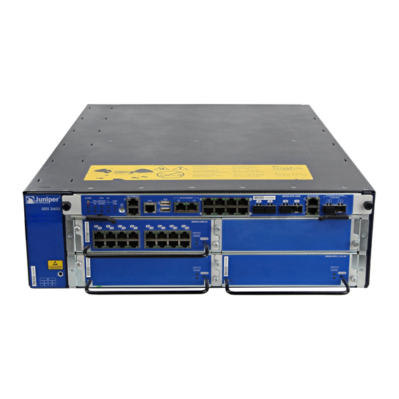
CHAPTER 1 System Overview SRX3400 Services Gateway Description on page 3 Data Flow in the SRX3400 Services Gateway on page 4 SRX3400 Services Gateway Description The SRX3400 Services Gateway is a high-performance, scalable, carrier-class security device with multi-processor architecture. The services gateway has a capacity of up to 20 gigabits per second (Gbps) in full duplex and is three rack units (U) tall. -
Page 26: Data Flow In The Srx3400 Services Gateway
SRX3400 Services Gateway Chassis on page 19 Documentation Available Components for the SRX3400 Services Gateway on page 5 Hardware Component Locations in the SRX3400 Services Gateway Chassis on page 20 Installation Overview for the SRX3400 Services Gateway on page 85 Copyright © 2017, Juniper Networks, Inc. -
Page 27: Hardware Component Overview
CHAPTER 2 Hardware Component Overview Available Components for the SRX3400 Services Gateway on page 5 SRX3400 Services Gateway CFMs on page 7 SRX3400 Services Gateway Switch Fabric Board on page 7 SRX3400 Services Gateway NPCs on page 13 SRX3400 Services Gateway SPCs on page 13... -
Page 28: Table 4: Supported Combinations Of Spcs, Npcs, And Iocs
Table 4 on page 6 shows the supported combinations of SPCs, NPCs, and IOCs that can be installed in the SRX3400 Services Gateway. The support is different between standard and enhanced DC-powered services gateways because the standard DC power supplies have a lower power rating. -
Page 29: Srx3400 Services Gateway Cfms
Documentation SRX3400 Services Gateway Description on page 3 Hardware Component Locations in the SRX3400 Services Gateway Chassis on page 20 Available Components for the SRX3400 Services Gateway on page 5 Data Flow in the SRX3400 Services Gateway on page 4 SRX3400 Services Gateway Switch Fabric Board The Switch Fabric Board (SFB) is the data plane for the subsystems in the chassis. -
Page 30: Table 5: Power Button Behavior
SRX3400 Services Gateway Hardware Guide Table 5 on page 8 describes the behavior of the Power button near the left end of the SFB front panel. Table 5: Power Button Behavior Condition Action Result Services Short push (3 to 5 Powers the services gateway on. - Page 31 The SFB or one or more of the installed CFM cards has failed. The LEDs on the failed CFM SERVICE cards are red. Dark One or more of the installed CFM cards are disabled. (unlit) SERVICE LEDs on the disabled CFM cards are dark. Copyright © 2017, Juniper Networks, Inc.
- Page 32 SRX3400 Services Gateway Hardware Guide Table 6: Switch Fabric Board LED Indicators (continued) Label Color Status Indicated Behavior Green On steadily The SFB and all installed CFM cards are operating OK/FAIL (bottom) normally. The LEDs on all installed CFM OK/FAIL cards are green.
-
Page 33: Table 7: Switch Fabric Board Front Panel Ports And Connectors
Unused. (top), Universal serial bus connectors that can be managed and accessed USB0 by the master Routing Engine. USB1 (bottom) RJ-45 port used to manage the Routing Engine in slot RE0. RE ETHERNET 0 Copyright © 2017, Juniper Networks, Inc. - Page 34 Technical Assistance Center (JTAC) can help you diagnose the source of the problem. Your JTAC engineer might recommend that you check the third-party optic or cable and potentially replace it with an equivalent Juniper Networks optic or cable that is qualified for the device. Related...
-
Page 35: Srx3400 Services Gateway Npcs
Related SRX3400 Services Gateway Chassis on page 19 Documentation Installing CFM Cards in the SRX3400 Services Gateway on page 103 Available Components for the SRX3400 Services Gateway on page 5 SRX3400 Services Gateway Switch Fabric Board on page 7 SRX3400 Services Gateway SPCs on page 13... -
Page 36: Srx3400 Services Gateway Iocs
Network Processing Card (NPC) and to forward data packets out the physical ports after services processing. The SRX3400 Services Gateway has four slots in the front of the chassis where you can install IOCs. You can install any combination of IOCs in the slots. -
Page 37: Srx3400 Services Gateway Np-Iocs
Related SRX3400 Services Gateway Chassis on page 19 Documentation Installing CFM Cards in the SRX3400 Services Gateway on page 103 Available Components for the SRX3400 Services Gateway on page 5 SRX3400 Services Gateway Switch Fabric Board on page 7 SRX3400 Services Gateway NPCs on page 13... -
Page 38: Srx3400 Services Gateway Routing Engine
Related SRX3400 Services Gateway Chassis on page 19 Documentation Installing CFM Cards in the SRX3400 Services Gateway on page 103 Available Components for the SRX3400 Services Gateway on page 5 SRX3400 Services Gateway Switch Fabric Board on page 7 SRX3400 Services Gateway NPCs on page 13... -
Page 39: Srx3400 Services Gateway Srx Clustering Module
Documentation Available Components for the SRX3400 Services Gateway on page 5 Hardware Component Locations in the SRX3400 Services Gateway Chassis on page 20 SRX3400 Services Gateway SRX Clustering Module The SRX Clustering Module (SCM) is a card that you can install in the services gateway to enable the dual control link feature for chassis cluster supported in Junos OS Release 10.2 and later. - Page 40 For detailed information about the SCMs supported by the services gateway, see the SRX1400, SRX3400, and SRX3600 Services Gateway Module Guide www.juniper.net/techpubs/ Related Installing an SCM in the SRX3400 Services Gateway on page 110 Documentation Copyright © 2017, Juniper Networks, Inc.
-
Page 41: Chassis Description
CHAPTER 3 Chassis Description SRX3400 Services Gateway Chassis on page 19 Hardware Component Locations in the SRX3400 Services Gateway Chassis on page 20 SRX3400 Services Gateway Midplane on page 22 SRX3400 Services Gateway Chassis The SRX3400 Services Gateway chassis, shown in... -
Page 42: Hardware Component Locations In The Srx3400 Services Gateway Chassis
Hardware Component Locations in the SRX3400 Services Gateway Chassis The SRX3400 Services Gateway is populated with one SFB, one Routing Engine, one power supply, and a fan tray plus air filter at the factory. You must install all other cards required to meet your configuration needs. -
Page 43: Figure 11: Front Slots On The Srx3400 Services Gateway
Chapter 3: Chassis Description Table 8: Allowed Slot Locations for the SRX3400 Services Gateway Components (continued) Module Name Allowed Slot Locations NPCs Rear slots labeled SPCs Front slots labeled and rear slots labeled Power supplies Rear slots (two) on bottom left of chassis. -
Page 44: Srx3400 Services Gateway Midplane
Installation Overview for the SRX3400 Services Gateway on page 85 SRX3400 Services Gateway Midplane The midplane in the SRX3400 Services Gateway is in the center of the chassis and provides connections for installing up to four common form-factor modules (CFMs) through the front of the chassis and up to three CFMs through the rear of the chassis. -
Page 45: Line Card And Module Description
SRX1400, SRX3400, and SRX3600 Services Gateway Module Overview The modules described in this guide let you upgrade and customize your SRX1400, SRX3400, or SRX3600 Services Gateway to suit the needs of your network. The following types of modules are available for the SRX1400, SRX3400, and SRX3600 Services... -
Page 46: Gateways
Related Modules Supported on SRX1400, SRX3400, and SRX3600 Services Gateways on Documentation page 24 Eligible Slots for SRX1400, SRX3400, and SRX3600 Services Gateway Modules on page 25 Installing Common Form Factor Modules In SRX1400, SRX3400, and SRX3600 Services Gateways Modules Supported on SRX1400, SRX3400, and SRX3600 Services Gateways... -
Page 47: Gateways
Not Applicable 10.2 10.2 Related SRX1400, SRX3400, and SRX3600 Services Gateway Module Overview on page 23 Documentation Eligible Slots for SRX1400, SRX3400, and SRX3600 Services Gateway Modules on page 25 Installing Common Form Factor Modules In SRX1400, SRX3400, and SRX3600 Services... -
Page 48: Table 10: Supported Slots For Srx1400, Srx3400, And Srx3600 Services Gateway Modules
SRX3400 Services Gateway Hardware Guide Table 10: Supported Slots for SRX1400, SRX3400, and SRX3600 Services Gateway Modules Supported Slots Module Name and Number SRX1400 SRX3400 SRX3600 “Services Processing Card Front slot labeled (When Front slots labeled Front slots labeled and rear SRX3K-SPC-1-10-40”... -
Page 49: Services Processing Card Srx3K-Spc-1-10-40
SRX3400, CFM slots through in the SRX3600). When an SRX3400 or SRX3600 Services Gateway is in the Express Path (formerly known as Services Offload) mode supported in Junos OS release 12.1X44-D10 and later, IOCs are only supported in front panel slots through . -
Page 50: Figure 15: Spc Serial Number Label
NOTE: For the SRX3400 Services Gateway to meet NEBS and ETSI standards, it must not have any two SPCs installed side by side in the CFM slots in the front of the chassis (CFM slots through ). -
Page 51: Network Processing Card Srx3K-Npc
Chapter 4: Line Card and Module Description Eligible Slots for SRX1400, SRX3400, and SRX3600 Services Gateway Modules on page 25 Installing Common Form Factor Modules In SRX1400, SRX3400, and SRX3600 Services Gateways Network Processing Card SRX3K-NPC Network Processing Cards (NPCs) are CFMs that receive inbound traffic from the IOCs and direct it to the appropriate SPC for services processing. -
Page 52: I/O Card Srx3K-16Ge-Tx
Serial number label SR X3K -NP Related SRX1400, SRX3400, and SRX3600 Services Gateway Module Overview on page 23 Documentation Modules Supported on SRX1400, SRX3400, and SRX3600 Services Gateways on page 24 Eligible Slots for SRX1400, SRX3400, and SRX3600 Services Gateway Modules on... -
Page 53: Figure 18: 16-Port Copper 10/100/1000 Ioc
(except as noted below) NOTE: When an SRX3400 or SRX3600 Services Gateway is in the Express Path (formerly known as Services Offload) mode supported in Junos OS release 12.1X44-D10 and later, IOCs are only supported in front panel slots through . -
Page 54: I/O Card Srx3K-16Ge-Sfp
IOCs Similar) Serial number label Related SRX1400, SRX3400, and SRX3600 Services Gateway Module Overview on page 23 Documentation Modules Supported on SRX1400, SRX3400, and SRX3600 Services Gateways on page 24 Eligible Slots for SRX1400, SRX3400, and SRX3600 Services Gateway Modules on... - Page 55 (except as noted below) NOTE: When an SRX3400 or SRX3600 Services Gateway is in the Express Path (formerly known as Services Offload) mode supported in Junos OS release 12.1X44-D10 and later, IOCs are only supported in front panel slots through .
-
Page 56: I/O Card Srx3K-2Xge-Xfp
IOCs Similar) Serial number label Related SRX1400, SRX3400, and SRX3600 Services Gateway Module Overview on page 23 Documentation Modules Supported on SRX1400, SRX3400, and SRX3600 Services Gateways on page 24 Eligible Slots for SRX1400, SRX3400, and SRX3600 Services Gateway Modules on... - Page 57 (except as noted below) NOTE: When an SRX3400 or SRX3600 Services Gateway is in the Express Path (formerly known as Services Offload) mode supported in Junos OS release 12.1X44-D10 and later, IOCs are only supported in front panel slots through .
-
Page 58: Network Processing I/O Card Srx1K3K-Np-2Xge-Sfpp
IOCs Similar) Serial number label Related SRX1400, SRX3400, and SRX3600 Services Gateway Module Overview on page 23 Documentation Modules Supported on SRX1400, SRX3400, and SRX3600 Services Gateways on page 24 Eligible Slots for SRX1400, SRX3400, and SRX3600 Services Gateway Modules on... - Page 59 For detailed information about supported transceivers, see the SRX Series Services Gateway Transceiver Guide www.juniper.net/techpubs/ Description 2-port Ethernet SFP+ NP-IOC for SRX3400, SRX3600, and SRX1400 Services Gateways Power requirement: 52 W maximum Weight: 2.4 lb (1.1 kg) Maximum configurable MTU: 9192 bytes Software release Junos OS Release 12.1X44-D10 and later...
-
Page 60: Routing Engines Srx3K-Re-12-10 And Srx1K-Re-12-10
IOCs Similar) Serial number label Related SRX1400, SRX3400, and SRX3600 Services Gateway Module Overview on page 23 Documentation Modules Supported on SRX1400, SRX3400, and SRX3600 Services Gateways on page 24 Eligible Slots for SRX1400, SRX3400, and SRX3600 Services Gateway Modules on... -
Page 61: Figure 26: Routing Engine
Figure 26: Routing Engine (SRX3K-RE-12-10 Shown, SRX1K-RE-12-10 Similar) Description Routing Engine for SRX1400 Services Gateway (SRX1K-RE-12-10) Routing Engine for SRX3400 or SRX3600 Services Gateway (SRX3K-RE-12-10) Power requirement: 53 W maximum Weight: 2.9 lb (1.3 kg) Software release SRX3K-RE-12-10: Junos OS Release 9.3 and later SRX1K-RE-12-10: Junos OS Release 10.2 and later... -
Page 62: Figure 27: Routing Engine Serial Number Label
Figure 27: Routing Engine Serial Number Label Serial number label Related SRX1400, SRX3400, and SRX3600 Services Gateway Module Overview on page 23 Documentation Modules Supported on SRX1400, SRX3400, and SRX3600 Services Gateways on page 24 Eligible Slots for SRX1400, SRX3400, and SRX3600 Services Gateway Modules on... -
Page 63: Srx Clustering Module Srx3K-Crm
Chapter 4: Line Card and Module Description SRX Clustering Module SRX3K-CRM The SRX Clustering Module (SCM) is a card that you can install in the SRX3400 and SRX3600 Services Gateway to enable the dual control link feature for chassis cluster supported in Junos OS Release 10.2 and later... -
Page 64: Figure 29: Scm Serial Number Label
Location Figure 29: SCM Serial Number Label Serial number label Related SRX1400, SRX3400, and SRX3600 Services Gateway Module Overview on page 23 Documentation Modules Supported on SRX1400, SRX3400, and SRX3600 Services Gateways on page 24 Eligible Slots for SRX1400, SRX3400, and SRX3600 Services Gateway Modules on... -
Page 65: Cooling System Description
The SRX3400 Services Gateway has one fan tray located in the rear of the services gateway that installs vertically to the right of the card cage. -
Page 66: Figure 31: Airflow Through The Chassis
Routing Engine shuts down the system by disabling output power from each power supply. Related SRX3400 Services Gateway Chassis on page 19 Documentation Hardware Component Locations in the SRX3400 Services Gateway Chassis on page 20 Copyright © 2017, Juniper Networks, Inc. -
Page 67: Srx3400 And Srx5600 Services Gateways Air Deflector Kits
Replacing the Fan Tray on the SRX3400 Services Gateway on page 189 SRX3400 and SRX5600 Services Gateways Air Deflector Kits Optional air deflector kits are available that let you install the SRX3400 and SRX5600 Services Gateways in a hot aisle/cold aisle ventilation environment. These kits convert the services gateway from side-to-side ventilation into front-to-back ventilation. -
Page 68: Figure 32: Srx3400 Services Gateway Air Deflector Kit
SRX3400 and SRX5600 Services Gateways, respectively, installed in typical four-post mounting racks with the air deflector kit parts in place. Figure 32: SRX3400 Services Gateway Air Deflector Kit Figure 33: SRX5600 Services Gateway Air Deflector Kit (Services Gateway Chassis Contents Omitted for Clarity) -
Page 69: Power System Description
SRX3400 Services Gateway DC Power Supply Overview on page 48 SRX3400 Services Gateway AC Power Supply Overview In an AC power configuration, the SRX3400 Services Gateway contains one or two AC power supplies, located at the rear of the chassis in slots PEM0 and PEM1. Each power supply provides power to all components in the services gateway. -
Page 70: Srx3400 Services Gateway Dc Power Supply Overview
SRX3400 Services Gateway Hardware Guide SRX3400 Services Gateway DC Power Supply Overview In a DC power configuration, the SRX3400 Services Gateway contains one or two DC power supplies, located at the rear of the chassis in slots PEM0 and PEM1. Each power supply provides power to all components in the services gateway. -
Page 71: Site Planning And Specifications
Rack Requirements on page 57 Cabinet Requirements on page 61 Grounding Specifications on page 63 AC Power Requirements and Specifications on page 65 DC Power Requirements and Specifications on page 71 Cable Specifications and Pinouts on page 77 Copyright © 2017, Juniper Networks, Inc. - Page 72 SRX3400 Services Gateway Hardware Guide Copyright © 2017, Juniper Networks, Inc.
-
Page 73: Planning And Preparing The Site
SRX3400 Services Gateway Physical Specifications on page 52 SRX3400 Services Gateway Environmental Specifications on page 53 Site Preparation Checklist for the SRX3400 Services Gateway on page 54 General Site Guidelines Efficient device operation requires proper site planning and maintenance and proper layout of the equipment, rack or cabinet (if used), and wiring closet. -
Page 74: Srx3400 Services Gateway Physical Specifications
SRX3400 Services Gateway Hardware Guide WARNING: It is particularly important to provide a properly grounded and shielded environment and to use electrical surge-suppression devices. Table 13: Site Electrical Wiring Guidelines Site Wiring Factor Guidelines Signaling limitations If your site experiences any of the following problems, consult... -
Page 75: Srx3400 Services Gateway Environmental Specifications
Related Available Components for the SRX3400 Services Gateway on page 5 Documentation Hardware Component Locations in the SRX3400 Services Gateway Chassis on page 20 SRX3400 Services Gateway Chassis on page 19 SRX3400 Services Gateway Environmental Specifications Table 15 on page 54 specifies the environmental specifications required for normal services gateway operation. -
Page 76: Site Preparation Checklist For The Srx3400 Services Gateway
SRX3400 Services Gateway Agency Approvals on page 259 Documentation SRX3400 Services Gateway General Safety Guidelines and Warnings SRX3400 Services Gateway Fire Safety Requirements and Fire Suppression Equipment SRX3400 Services Gateway Definition of Safety Warning Levels Site Preparation Checklist for the SRX3400 Services Gateway... - Page 77 “Calculating the Power Margin for Fiber-Optic Cable for the SRX3400 Services Gateway” on page 81 Related Installation Overview for the SRX3400 Services Gateway on page 85 Documentation Unpacking the SRX3400 Services Gateway on page 87 Copyright © 2017, Juniper Networks, Inc.
- Page 78 SRX3400 Services Gateway Hardware Guide Copyright © 2017, Juniper Networks, Inc.
-
Page 79: Rack Requirements
Cabinets, Racks, Panels, and Associated Equipment (document number EIA-310-D) published by the Electronics Industry Association. You can stack eight SRX3400 Services Gateways in a rack that has at least 40 U (70 in. or 1.78 m) of usable vertical space. -
Page 80: Srx3400 Services Gateway Spacing Of Mounting Bracket Holes
Clearance Requirements for Airflow and Hardware Maintenance of the SRX3400 Services Gateway on page 59 Connecting the SRX3400 Services Gateway to the Building Structure on page 59 SRX3400 Services Gateway Spacing of Mounting Bracket Holes The services gateway can be mounted in any rack that provides holes or hole patterns spaced at 1 U (1.75 in.) increments. -
Page 81: Connecting The Srx3400 Services Gateway To The Building Structure
Related Rack-Mounting Requirements and Warnings Documentation SRX3400 Services Gateway Rack Size and Strength Requirements on page 57 Clearance Requirements for Airflow and Hardware Maintenance of the SRX3400 Services Gateway on page 59 SRX3400 Services Gateway Spacing of Mounting Bracket Holes on page 58... -
Page 82: Figure 37: Clearance Requirements
SRX3400 Services Gateway Rack Size and Strength Requirements on page 57 Documentation Connecting the SRX3400 Services Gateway to the Building Structure on page 59 SRX3400 Services Gateway Spacing of Mounting Bracket Holes on page 58 Copyright © 2017, Juniper Networks, Inc. -
Page 83: Cabinet Requirements
CHAPTER 9 Cabinet Requirements SRX3400 Services Gateway Cabinet Size and Clearance Requirements on page 61 SRX3400 Services Gateway Cabinet Airflow Requirements on page 62 SRX3400 Services Gateway Cabinet Size and Clearance Requirements The minimum size cabinet that can accommodate the services gateway is 27.5 in. -
Page 84: Srx3400 Services Gateway Cabinet Airflow Requirements
Route and dress all cables to minimize the blockage of airflow to and from the chassis. For more information about air flow through the services gateway, see SRX3400 and SRX5600 Services Gateways Air Deflector Kits. -
Page 85: Grounding Specifications
CHAPTER 10 Grounding Specifications SRX3400 Services Gateway Grounding-Cable Lug Specification on page 63 SRX3400 Services Gateway Grounding Cable Specification on page 63 SRX3400 Services Gateway Grounding-Cable Lug Specification The cable attaches to the grounding cable (see Figure 38 on page 63) and two M5 screws are used to secure the grounding cable to the grounding point. -
Page 86: Table 17: Grounding Cable Specifications
See “Grounding the SRX3400 Services Gateway” on page 117 for instructions. Related SRX3400 Services Gateway Chassis Grounding Point on page 115 Documentation SRX3400 Services Gateway Grounding-Cable Lug Specification on page 63 Copyright © 2017, Juniper Networks, Inc. -
Page 87: Ac Power Requirements And Specifications
CHAPTER 11 AC Power Requirements and Specifications SRX3400 Services Gateway AC Power Supply Electrical Specifications on page 65 SRX3400 Services Gateway AC Power System Electrical Specifications on page 66 SRX3400 Services Gateway AC Power Cord Specifications on page 67 Power Requirements for AC-Powered SRX3400 Services Gateways on page 69... -
Page 88: Srx3400 Services Gateway Ac Power System Electrical Specifications
Related SRX3400 Services Gateway Chassis on page 19 Documentation Hardware Component Locations in the SRX3400 Services Gateway Chassis on page 20 SRX3400 Services Gateway AC Power Supply Overview on page 47 SRX3400 Services Gateway AC Power System Electrical Specifications Table 20 on page 66 lists the AC power system electrical specifications. -
Page 89: Srx3400 Services Gateway Ac Power Cord Specifications
Chapter 11: AC Power Requirements and Specifications SRX3400 Services Gateway AC Power Cord Specifications Each AC power supply has a single AC appliance inlet located on the power supply that requires a dedicated AC power feed and a dedicated 15 A (250 VAC) circuit breaker. Most... -
Page 90: Figure 39: Ac Plug Types
“Replacing AC Power Supply Cables on the SRX3400 Services Gateway” on page 198. Related SRX3400 Services Gateway AC Power System Electrical Specifications on page 66 Documentation SRX3400 Services Gateway AC Power Supply Electrical Specifications Power Requirements for AC-Powered SRX3400 Services Gateways on page 69... -
Page 91: Power Requirements For Ac-Powered Srx3400 Services Gateways
Chapter 11: AC Power Requirements and Specifications Power Requirements for AC-Powered SRX3400 Services Gateways NOTE: If you plan to operate a maximally configured AC-powered services gateway, we recommend that you provision 6 A @ 240 VAC (or 14 A @ 100 VAC) for the system. - Page 92 Watts * 3.41 = BTU/hr 1079 W * 3.41 = 3679 BTU/hr Related SRX3400 Services Gateway AC Power System Electrical Specifications on page 66 Documentation SRX3400 Services Gateway AC Power Supply Electrical Specifications SRX3400 Services Gateway AC Power Cord Specifications on page 67...
-
Page 93: Dc Power Requirements And Specifications
CHAPTER 12 DC Power Requirements and Specifications SRX3400 Services Gateway DC Power Supply Electrical Specifications on page 71 SRX3400 Services Gateway DC Power System Electrical Specifications on page 72 SRX3400 Services Gateway DC Power Cable Specifications on page 73 Power Requirements for DC-Powered SRX3400 Services Gateways on page 74 SRX3400 Services Gateway DC Power Supply Electrical Specifications Two types of DC power supply are available. -
Page 94: Srx3400 Services Gateway Dc Power System Electrical Specifications
Related SRX3400 Services Gateway Chassis on page 19 Documentation Hardware Component Locations in the SRX3400 Services Gateway Chassis on page 20 SRX3400 Services Gateway DC Power Supply Overview on page 48 SRX3400 Services Gateway DC Power System Electrical Specifications Table 26 on page 72 lists the DC power system electrical specifications. -
Page 95: Srx3400 Services Gateway Dc Power Cable Specifications
SRX3400 Services Gateway DC Power Cable Specifications Figure 40 on page 73 shows a typical DC source cabling arrangement. Figure 40: Typical DC Source Cabling to the SRX3400 Services Gateway The DC power supply in slot must be powered by dedicated power feeds derived... -
Page 96: Power Requirements For Dc-Powered Srx3400 Services Gateways
“Connecting the SRX3400 Services Gateway to a DC Power Source” on page 125. For instructions on replacing a DC power cable, see “Replacing DC Power Supply Cables on the SRX3400 Services Gateway” on page 203. Table 27 on page 74 summarizes the specifications for the power cables, which you must supply. -
Page 97: Table 29: Component Dc Power Requirements
Watts DC * 3.41 = BTU/hr 1004 * 3.41 = 3424 BTU/hr Related SRX3400 Services Gateway DC Power System Electrical Specifications on page 72 Documentation SRX3400 Services Gateway DC Power Supply Electrical Specifications on page 71 SRX3400 Services Gateway DC Power Cable Specifications on page 73... - Page 98 SRX3400 Services Gateway Hardware Guide Copyright © 2017, Juniper Networks, Inc.
-
Page 99: Cable Specifications And Pinouts
Console Port Cable and Wire Specifications for the SRX3400 Services Gateway on page 77 Distance Limitations for Signaling for the SRX3400 Services Gateway on page 78 Radio Frequency Interference for the SRX3400 Services Gateway on page 78 Electromagnetic Compatibility for the SRX3400 Services Gateway on page 78... -
Page 100: Distance Limitations For Signaling For The Srx3400 Services Gateway
If you must exceed the recommended distances, use a high-quality twisted-pair cable with one ground conductor for each data signal when applicable. Related Distance Limitations for Signaling for the SRX3400 Services Gateway on page 78 Documentation Electromagnetic Compatibility for the SRX3400 Services Gateway on page 78... -
Page 101: Signal Loss In Multimode And Single-Mode Fiber-Optic Cable For The Srx3400 Services Gateway
Chapter 13: Cable Specifications and Pinouts Signal Loss in Multimode and Single-Mode Fiber-Optic Cable for the SRX3400 Services Gateway Multimode fiber is large enough in diameter to allow rays of light to reflect internally (bounce off the walls of the fiber). Interfaces with multimode optics typically use LEDs as light sources. - Page 102 (including those from dispersion), and a safety margin for unexpected losses. Related Signal Loss in Multimode and Single-Mode Fiber-Optic Cable for the SRX3400 Services Documentation Gateway on page 79 Calculating the Power Budget for Fiber-Optic Cable for the SRX3400 Services Gateway...
-
Page 103: Table 31: Estimated Values For Factors That Cause Link Loss
Chapter 13: Cable Specifications and Pinouts Calculating the Power Margin for Fiber-Optic Cable for the SRX3400 Services Gateway After calculating a link's power budget, you can calculate the power margin (P ), which represents the amount of power available after subtracting attenuation or link loss (LL) from the power budget (P ). -
Page 104: Gateway
Related Signal Loss in Multimode and Single-Mode Fiber-Optic Cable for the SRX3400 Services Documentation Gateway on page 79 Attenuation and Dispersion in Fiber-Optic Cable for the SRX3400 Services Gateway... -
Page 105: Initial Installation And Configuration
Unpacking the Services Gateway on page 87 Installing the Mounting Hardware on page 91 Installing the SRX3400 Services Gateway Using a Mechanical Lift on page 93 Installing the SRX3400 Services Gateway Without a Mechanical Lift on page 97 Installing Additional Hardware Components on page 103... - Page 106 SRX3400 Services Gateway Hardware Guide Copyright © 2017, Juniper Networks, Inc.
-
Page 107: Installation Overview
54, you are ready to unpack and install the services gateway. It is important to proceed through the installation process in the following order: Review the safety guidelines explained in SRX3400 Services Gateway Definition of Safety Warning Levels. Install the services gateway, as described in “Installing the SRX3400 Services Gateway... - Page 108 SRX3400 Services Gateway Hardware Guide Related SRX3400 Services Gateway Chassis on page 19 Documentation Routine Maintenance Procedures for the SRX3400 Services Gateway on page 143 Copyright © 2017, Juniper Networks, Inc.
-
Page 109: Unpacking The Services Gateway
CHAPTER 15 Unpacking the Services Gateway Required Tools and Parts for Unpacking the SRX3400 Services Gateway on page 87 Unpacking the SRX3400 Services Gateway on page 87 Verifying Parts Received with the SRX3400 Services Gateway on page 89 Required Tools and Parts for Unpacking the SRX3400 Services Gateway... -
Page 110: Figure 41: Unpacking The Srx3400 Services Gateway
Remove the plastic handle inserts and lift the cardboard cover off the services gateway. Remove the foam covering the top of the services gateway. Remove the accessory box, the mounting shelf, and the SRX3400 Services Gateway Getting Started Guide. Figure 41: Unpacking the SRX3400 Services Gateway With a person on each side of the carton, carefully lift the services gateway from the carton and place on lift. -
Page 111: Verifying Parts Received With The Srx3400 Services Gateway
“Installing the SRX3400 Services Gateway in a Rack or Cabinet Using a Mechanical Lift” on page Related Required Tools and Parts for Unpacking the SRX3400 Services Gateway on page 87 Documentation Verifying Parts Received with the SRX3400 Services Gateway on page 89 Verifying Parts Received with the SRX3400 Services Gateway A packing list is included in each shipment. -
Page 112: Table 33: Accessory Box Parts List
Juniper Compliance Form Letter; RoHS Document sleeve ESD wrist strap with cable Related Required Tools and Parts for Unpacking the SRX3400 Services Gateway on page 87 Documentation Unpacking the SRX3400 Services Gateway on page 87 Copyright © 2017, Juniper Networks, Inc. -
Page 113: Installing The Mounting Hardware
CHAPTER 16 Installing the Mounting Hardware Installing the Mounting Hardware for the SRX3400 Services Gateway on page 91 Installing the Mounting Hardware for the SRX3400 Services Gateway The specific mounting hardware used depends on the type of rack being utilized. Use the appropriate procedure steps to install the mounting hardware for your situation. -
Page 114: Figure 43: Attaching Mounting Hardware For Cabinet Or Four-Post Rack
SRX3400 Services Gateway Definition of Safety Warning Levels Documentation Preparing the SRX3400 Services Gateway for Rack-Mount or Cabinet Installation on page 93 Installing the SRX3400 Services Gateway in a Rack or Cabinet Using a Mechanical Lift on page 94 Copyright © 2017, Juniper Networks, Inc. -
Page 115: Installing The Srx3400 Services Gateway Using A Mechanical Lift
93 Installing the Mounting Hardware for the SRX3400 Services Gateway on page 91 Installing the SRX3400 Services Gateway in a Rack or Cabinet Using a Mechanical Lift on page 94 Preparing the SRX3400 Services Gateway for Rack-Mount or Cabinet Installation Before you begin the installation, verify the following: Your site has been properly prepared for the services gateway. -
Page 116: Mechanical Lift
Documentation Installing the Mounting Hardware for the SRX3400 Services Gateway on page 91 Installing the SRX3400 Services Gateway in a Rack or Cabinet Using a Mechanical Lift on page 94 Installing the SRX3400 Services Gateway in a Rack or Cabinet Using a Mechanical Lift Ensure the rack is in its permanent location and is secured to the building. -
Page 117: Figure 46: Installing The Services Gateway In A Two-Post Rack
Chapter 17: Installing the SRX3400 Services Gateway Using a Mechanical Lift Using the lift, position the services gateway in the rack: For two-post rack mounting, align the bottom hole in each mounting bracket with a hole in each rack rail. - Page 118 Related SRX3400 Services Gateway Definition of Safety Warning Levels Documentation Preparing the SRX3400 Services Gateway for Rack-Mount or Cabinet Installation on page 93 Copyright © 2017, Juniper Networks, Inc.
-
Page 119: Installing The Srx3400 Services Gateway Without A Mechanical Lift
Required Tools for Installing the SRX3400 Services Gateway Without a Mechanical Lift on page 97 Removing Components from the Chassis for Manual Lifting of the SRX3400 Services Gateway on page 97 Lifting the SRX3400 Services Gateway Chassis into the Rack on page 99... -
Page 120: Figure 48: Components To Remove From The Front Of The Services Gateway
Attach an ESD grounding strap to your bare wrist and connect the strap to one of the ESD points on the chassis. For more information about ESD, see Preventing Electrostatic Discharge Damage to the SRX3400 Services Gateway. If you have not already done so, power off the services gateway by pressing the Power button on the front panel of the SFB for three to five seconds. -
Page 121: Lifting The Srx3400 Services Gateway Chassis Into The Rack
Required Tools for Installing the SRX3400 Services Gateway Without a Mechanical Documentation Lift on page 97 Lifting the SRX3400 Services Gateway Chassis into the Rack on page 99 Reinstalling Components in the SRX3400 Services Gateway Chassis on page 100 Lifting the SRX3400 Services Gateway Chassis into the Rack Lifting the chassis and mounting it in a rack requires two people. -
Page 122: Reinstalling Components In The Srx3400 Services Gateway Chassis
Related Installing the Mounting Hardware for the SRX3400 Services Gateway on page 91 Documentation Required Tools for Installing the SRX3400 Services Gateway Without a Mechanical... - Page 123 Chapter 18: Installing the SRX3400 Services Gateway Without a Mechanical Lift Removing Components from the Chassis for Manual Lifting of the SRX3400 Services Gateway on page 97 Lifting the SRX3400 Services Gateway Chassis into the Rack on page 99 Copyright © 2017, Juniper Networks, Inc.
- Page 124 SRX3400 Services Gateway Hardware Guide Copyright © 2017, Juniper Networks, Inc.
-
Page 125: Installing Additional Hardware Components
Components Installing CFM Cards in the SRX3400 Services Gateway on page 103 Installing SPCs in an Operating SRX3400 Services Gateway Chassis Cluster on page 106 Installing an SCM in the SRX3400 Services Gateway on page 110 Installing an AC Power Supply in the SRX3400 Services Gateway on page 111... - Page 126 (CFM slots 1 through 4). You can install SPCs side by side in the CFM slots in the rear of the chassis (CFM slots 5 through 7). “SRX3400 Services Gateway NEBS and ETSI Compliance” on page 261 for more information.
-
Page 127: Figure 51: Installing A Cfm (Spc Shown, Other Cfms Similar)
CFM cards. The handles might come off, causing the chassis to drop and inflicting possible grave injury. Related Preventing Electrostatic Discharge Damage to the SRX3400 Services Gateway Documentation SRX3400 Services Gateway NEBS and ETSI Compliance on page 261 Copyright © 2017, Juniper Networks, Inc. -
Page 128: Installing Spcs In An Operating Srx3400 Services Gateway Chassis Cluster
SRX3400 Services Gateway Hardware Guide Installing SPCs in an Operating SRX3400 Services Gateway Chassis Cluster on page 106 Hardware Component Locations in the SRX3400 Services Gateway Chassis on page 20 Installing SPCs in an Operating SRX3400 Services Gateway Chassis Cluster If your SRX3600 Services Gateway is part of a chassis cluster, you can install additional SPCs in the services gateways in the cluster without incurring downtime on your network. - Page 129 Chapter 19: Installing Additional Hardware Components To install SPCs in an SRX3400 Services Gateway cluster without incurring downtime: Use the console port on the Routing Engine to establish a command-line interface (CLI) session with one of the devices in the cluster.
- Page 130 In the example below, the second column shows that all of the cards are online. This example is for an SRX3400 Services Gateway; for other devices the output will be similar. admin@node1_device> show chassis fpc pic-status...
- Page 131 Use the show chassis cluster status command to make sure that the priority for all redundancy groups is greater than zero. Related Installing CFM Cards in the SRX3400 Services Gateway on page 103 Documentation Copyright © 2017, Juniper Networks, Inc.
-
Page 132: Installing An Scm In The Srx3400 Services Gateway
See Figure 52 on page 110. Figure 52: Installing the SCM in the SRX3400 Services Gateway Press both of the ejector handles inward to seat the SCM. Tighten the screws on either side of the SCM faceplate. -
Page 133: Installing An Ac Power Supply In The Srx3400 Services Gateway
NEBS and ETSI Compliance” on page 261 for more information. NOTE: The same AC power supply is used in both the SRX3400 and SRX3600 Services Gateways. However, this power supply is not interchangeable with that used in the SRX1400 Services Gateway. The SRX1400 Services Gateway power supply will fit into the SRX3400 Services Gateway, but will not work properly. -
Page 134: Figure 54: Installing An Ac Power Supply
The power supply faceplate should be flush with any adjacent power supply faceplate or blank installed in the power supply slot. “Connecting the SRX3400 Services Gateway to an AC Power Source” on page 123 for information on connecting the power supply to AC power. -
Page 135: Installing A Dc Power Supply In The Srx3400 Services Gateway
Gateway NEBS and ETSI Compliance” on page 261 for more information. NOTE: The same DC power supply is used in both the SRX3400 and SRX3600 Services Gateways. However, this power supply is not interchangeable with that used in the SRX1400 Services Gateway. The SRX1400 Services Gateway power supply will fit into the SRX3400 Services Gateway, but will not work properly. -
Page 136: Figure 56: Installing A Dc Power Supply
The power supply faceplate should be flush with any adjacent power supply faceplate. “Connecting the SRX3400 Services Gateway to a DC Power Source” on page 125 information on connecting the power supply to DC power. -
Page 137: Grounding The Srx3400 Services Gateway
CHAPTER 20 Grounding the SRX3400 Services Gateway Required Tools and Parts for Grounding and Providing Power to the SRX3400 Services Gateway on page 115 SRX3400 Services Gateway Chassis Grounding Point on page 115 Grounding the SRX3400 Services Gateway on page 117... -
Page 138: Figure 57: Grounding Point On Rear Of Srx3400 Services Gateway
M5 screws used to secure the grounding cable to the services gateway grounding point. Figure 57: Grounding Point on Rear of SRX3400 Services Gateway To ground the services gateway, you must connect a grounding cable to earth ground and then attach it to the chassis grounding point using the two screws provided. -
Page 139: Grounding The Srx3400 Services Gateway
Chapter 20: Grounding the SRX3400 Services Gateway Grounding the SRX3400 Services Gateway WARNING: To meet safety and electromagnetic interference (EMI) requirements and to ensure proper operation, you must properly ground the services gateway chassis before connecting power. You ground the services gateway by connecting a grounding cable to earth ground and then attaching it to the chassis grounding point using two M5 screws. -
Page 140: Figure 58: Connecting The Grounding Cable
Dress the grounding cable and verify that it does not touch or block access to services gateway components, and that it does not drape where people could trip on it. Related Required Tools and Parts for Grounding and Providing Power to the SRX3400 Services Documentation Gateway on page 115... -
Page 141: Connecting The Srx3400 Services Gateway To External Devices
CHAPTER 21 Connecting the SRX3400 Services Gateway to External Devices Required Tools and Parts for Connecting the SRX3400 Services Gateway on page 119 Connecting the SRX3400 Services Gateway to a Management Console or an Auxiliary Device on page 119 Connecting the SRX3400 Services Gateway to a Network for Out-of-Band... -
Page 142: Figure 59: Connecting To The Console Port
Data bits—8 Stop bits—1 Flow control—none Related Required Tools and Parts for Connecting the SRX3400 Services Gateway on page 119 Documentation Connecting the SRX3400 Services Gateway to a Network for Out-of-Band Management on page 121 Grounding the SRX3400 Services Gateway on page 117... -
Page 143: Figure 61: Sfb Ethernet Cable Connector
One Ethernet cable is provided with the services gateway. Plug the other end of the cable into the network device. Related Required Tools and Parts for Connecting the SRX3400 Services Gateway on page 119 Documentation Connecting the SRX3400 Services Gateway to a Management Console or an Auxiliary... - Page 144 SRX3400 Services Gateway Hardware Guide Copyright © 2017, Juniper Networks, Inc.
-
Page 145: Providing Power To The Srx3400 Services Gateway
Providing Power to the SRX3400 Services Gateway Connecting the SRX3400 Services Gateway to an AC Power Source on page 123 Connecting the SRX3400 Services Gateway to a DC Power Source on page 125 Powering On the SRX3400 Services Gateway on page 127... -
Page 146: Figure 62: Connecting To Ac Power
For example, if the services gateway loses power while the services gateway is on, when power returns, it will still be in the On state. Related Required Tools and Parts for Grounding and Providing Power to the SRX3400 Services Documentation Gateway on page 115 SRX3400 Services Gateway AC Power Cord Specifications on page 67 Copyright ©... -
Page 147: Connecting The Srx3400 Services Gateway To A Dc Power Source
Chapter 22: Providing Power to the SRX3400 Services Gateway Grounding the SRX3400 Services Gateway on page 117 Connecting the SRX3400 Services Gateway to a DC Power Source on page 125 Powering On the SRX3400 Services Gateway on page 127 Powering Off the SRX3400 Services Gateway on page 128... - Page 148 SRX3400 Services Gateway Hardware Guide to chassis ground at the battery plant, you can use a multimeter to verify that the ohm output of the DC cables to chassis ground. The cable with very large -48V resistance (indicating an open circuit) to chassis ground will be...
-
Page 149: Powering On The Srx3400 Services Gateway
For example, if the services gateway loses power while the services gateway is on, when power returns, it will still be in the On state. Related Required Tools and Parts for Grounding and Providing Power to the SRX3400 Services Documentation Gateway on page 115... -
Page 150: Powering Off The Srx3400 Services Gateway
On state. Related Required Tools and Parts for Grounding and Providing Power to the SRX3400 Services Documentation Gateway on page 115 Grounding the SRX3400 Services Gateway on page 117... - Page 151 On state. Related Required Tools and Parts for Grounding and Providing Power to the SRX3400 Services Documentation Gateway on page 115 Grounding the SRX3400 Services Gateway on page 117...
- Page 152 SRX3400 Services Gateway Hardware Guide Copyright © 2017, Juniper Networks, Inc.
-
Page 153: Performing The Initial Configuration
Performing the Initial Configuration SRX3400 Services Gateway Software Configuration Overview on page 131 Performing Initial Software Configuration on the SRX3400 Services Gateway on page 132 Performing Initial Software Configuration Using J-Web on page 136 SRX3400 Services Gateway Software Configuration Overview The services gateway is shipped with the Junos operating system (Junos OS) preinstalled and ready to be configured when the services gateway is powered on. -
Page 154: Gateway
SRX3400 Services Gateway Hardware Guide Performing Initial Software Configuration on the SRX3400 Services Gateway This procedure connects the services gateway to the network but does not enable it to forward traffic. For complete information about enabling the services gateway to forward traffic, including examples, see the appropriate Junos OS configuration guides. - Page 155 Configure basic security policies. [edit] admin@# set security policies from-zone trust to-zone untrust policy policy-name match source-address any destination-address any application any admin@# set security policies from-zone trust to-zone untrust policy policy-name then permit Copyright © 2017, Juniper Networks, Inc.
- Page 156 SRX3400 Services Gateway Hardware Guide Check the configuration for validity. [edit] admin@# commit check configuration check succeeds Commit the configuration to activate it on the services gateway. [edit] admin@# commit commit complete Optionally, display the configuration to verify that it is correct.
- Page 157 { security-zone trust { interfaces { ge-0/0/0.0; security-zone untrust { interfaces { ge-0/0/1.0; policies { from-zone trust to-zone untrust { policy bob { match { source-address any; destination-address any; application any; then { permit; Copyright © 2017, Juniper Networks, Inc.
-
Page 158: Performing Initial Software Configuration Using J-Web
[edit] admin@# exit admin@# Related SRX3400 Services Gateway Software Configuration Overview on page 131 Documentation SRX3400 Services Gateway Switch Fabric Board on page 7 Performing Initial Software Configuration Using J-Web Configuring Root Authentication and the Management Interface from the CLI on page 136... -
Page 159: Configuring Interfaces, Zones, And Policies With J-Web
Configure the device with J-Web using the following procedures. Configuring the Hostname on page 138 Configuring Interfaces on page 138 Configuring Zones and Assigning Interfaces on page 139 Configuring Security Policies on page 139 Copyright © 2017, Juniper Networks, Inc. -
Page 160: Configuring The Hostname
SRX3400 Services Gateway Hardware Guide Configuring the Hostname To configure the hostname: Launch a Web browser from the management device. Enter the IP address of the device in the URL address field. Specify the default username as root and enter the password. See “Configuring Root... -
Page 161: Configuring Zones And Assigning Interfaces
. The Add Policy dialog box appears. In the Policy tab, enter the policy name and set the policy action to . Then select permit Zone and set the From Zone to trust and the To Zone to untrust Copyright © 2017, Juniper Networks, Inc. - Page 162 Performing Initial Software Configuration on the SRX1400 Services Gateway (CLI Documentation Procedure) Performing Initial Software Configuration on the SRX3400 Services Gateway on page 132 Performing Initial Software Configuration on the SRX3600 Services Gateway Initially Configuring the SRX5400 Services Gateway Initially Configuring the SRX5600 Services Gateway Initially Configuring the SRX5800 Services Gateway Copyright ©...
-
Page 163: Maintaining And Troubleshooting Components
PART 4 Maintaining and Troubleshooting Components Maintaining Components on page 143 Troubleshooting Components on page 149 Copyright © 2017, Juniper Networks, Inc. - Page 164 SRX3400 Services Gateway Hardware Guide Copyright © 2017, Juniper Networks, Inc.
-
Page 165: Maintaining Components
Components on page 143 Routine Maintenance Procedures for the SRX3400 Services Gateway on page 143 Maintaining the Air Filter on the SRX3400 Services Gateway on page 144 Maintaining the Fan Tray on the SRX3400 Services Gateway on page 145 Maintaining the Routing Engine on the SRX3400 Services Gateway on page 146... -
Page 166: Maintaining The Air Filter On The Srx3400 Services Gateway
Do not run the services gateway for more than a few minutes without the air filter in place. Related Maintaining the Air Filter on the SRX3400 Services Gateway on page 144 Documentation Maintaining the Fan Tray on the SRX3400 Services Gateway on page 145... -
Page 167: Maintaining The Fan Tray On The Srx3400 Services Gateway
Components on page 143 Routine Maintenance Procedures for the SRX3400 Services Gateway on page 143 Maintaining the Air Filter on the SRX3400 Services Gateway on page 144 Maintaining the Routing Engine on the SRX3400 Services Gateway on page 146 Maintaining the Power Supplies on the SRX3400 Services Gateway on page 147... -
Page 168: Maintaining The Routing Engine On The Srx3400 Services Gateway
SRX3400 Services Gateway Hardware Guide Maintaining the Routing Engine on the SRX3400 Services Gateway The host subsystem comprises a Routing Engine installed directly into the midplane. To maintain the host subsystem components, follow these guidelines: Check the LEDs on the SFB faceplate. -
Page 169: Maintaining The Power Supplies On The Srx3400 Services Gateway
SRX3400 Services Gateway Routing Engine on page 16 Routine Maintenance Procedures for the SRX3400 Services Gateway on page 143 Maintaining the Air Filter on the SRX3400 Services Gateway on page 144 Maintaining the Fan Tray on the SRX3400 Services Gateway on page 145... - Page 170 SRX3400 Services Gateway Hardware Guide Copyright © 2017, Juniper Networks, Inc.
-
Page 171: Troubleshooting Components
CHAPTER 25 Troubleshooting Components Troubleshooting with the CLI on the SRX3400 Services Gateway on page 149 Troubleshooting with LEDs on the SRX3400 Services Gateway on page 150 Troubleshooting with Chassis and Interface Alarm Messages on the SRX3400 Services Gateway on page 150... -
Page 172: Troubleshooting With Leds On The Srx3400 Services Gateway
SRX3400 Services Gateway AC Power Supply Overview on page 47 SRX3400 Services Gateway DC Power Supply Overview on page 48 Troubleshooting with the CLI on the SRX3400 Services Gateway on page 149 Troubleshooting with Chassis and Interface Alarm Messages on the SRX3400 Services... -
Page 173: Table 34: Chassis Component Alarm Conditions On Srx3400 And Srx3600
Interface alarms—Indicate a problem with a specific network interface. Related Troubleshooting with the CLI on the SRX3400 Services Gateway on page 149 Documentation Troubleshooting with LEDs on the SRX3400 Services Gateway on page 150 Chassis Component Alarm Conditions on SRX3400 and SRX3600 Services Gateways... - Page 174 SRX3400 Services Gateway Hardware Guide Table 34: Chassis Component Alarm Conditions on SRX3400 and SRX3600 Services Gateways (continued) Chassis Alarm Component Alarm Condition Remedy Severity (High Some HA links are down Check for the links that are Yellow down and open a support...
- Page 175 Chapter 25: Troubleshooting Components Table 34: Chassis Component Alarm Conditions on SRX3400 and SRX3600 Services Gateways (continued) Chassis Alarm Component Alarm Condition Remedy Severity Routing Engine - Excessive framing errors on Replace the serial cable Yellow console port. connected to the device.
- Page 176 SRX3400 Services Gateway Hardware Guide Table 34: Chassis Component Alarm Conditions on SRX3400 and SRX3600 Services Gateways (continued) Chassis Alarm Component Alarm Condition Remedy Severity (Power A power supply has been Insert power supply into Yellow removed from the chassis.
- Page 177 Chapter 25: Troubleshooting Components Table 34: Chassis Component Alarm Conditions on SRX3400 and SRX3600 Services Gateways (continued) Chassis Alarm Component Alarm Condition Remedy Severity Temperature The chassis temperature has Check room temperature. Yellow exceeded 55 degrees C Check air filter and replace...
-
Page 178: Backup Routing Engine Alarms
SRX3400 Services Gateway Hardware Guide Backup Routing Engine Alarms For Services Gateways with master and backup Routing Engines, a master Routing Engine can generate alarms for events that occur on a backup Routing Engine. Table 35 on page 156 lists chassis alarms generated for a backup Routing Engine. -
Page 179: Troubleshooting The Cooling System On The Srx3400 Services Gateway
1-408-745-9500 (from outside the United States). Related SRX3400 Services Gateway Switch Fabric Board on page 7 Documentation SRX3600 Services Gateway Switch Fabric Board Troubleshooting the Cooling System on the SRX3400 Services Gateway The services gateway cooling system consists of a fan tray and an air filter, both of which are located vertically in the rear of the chassis. -
Page 180: Troubleshooting Iocs And Np-Iocs On The Srx3400 Services Gateway
If all power supplies have failed, the system temperature might have exceeded the threshold, causing the system to shut down. Related Replacing the Fan Tray on the SRX3400 Services Gateway on page 189 Documentation Troubleshooting with the CLI on the SRX3400 Services Gateway on page 149... - Page 181 Total DDR DRAM 0 MB Start time: 2008-11-04 07:07:51 PST Uptime: 5 hours, 48 minutes, 40 seconds Slot 4 information: State Online Temperature 40 degrees C / 104 degrees F Total CPU DRAM 1024 MB Copyright © 2017, Juniper Networks, Inc.
-
Page 182: Troubleshooting Npcs On The Srx3400 Services Gateway
For further description of the output from the commands, see the Junos System Basics and Services Command Reference. Related Troubleshooting with the CLI on the SRX3400 Services Gateway on page 149 Documentation Troubleshooting the Cooling System on the SRX3400 Services Gateway on page 157... -
Page 183: Troubleshooting Spcs On The Srx3400 Services Gateway
For further description of the output from the commands, see the Junos System Basics and Services Command Reference. Related Troubleshooting with the CLI on the SRX3400 Services Gateway on page 149 Documentation Troubleshooting the Cooling System on the SRX3400 Services Gateway on page 157... -
Page 184: Troubleshooting The Power System On The Srx3400 Services Gateway
For further description of the output from the commands, see the Junos System Basics and Services Command Reference. Related Troubleshooting with the CLI on the SRX3400 Services Gateway on page 149 Documentation Troubleshooting the Cooling System on the SRX3400 Services Gateway on page 157... - Page 185 SRX3400 Services Gateway AC Power Supply Electrical Specifications on page 65 Documentation Troubleshooting with the CLI on the SRX3400 Services Gateway on page 149 Troubleshooting the Cooling System on the SRX3400 Services Gateway on page 157 Troubleshooting IOCs and NP-IOCs on the SRX3400 Services Gateway on page 158...
- Page 186 SRX3400 Services Gateway Hardware Guide Copyright © 2017, Juniper Networks, Inc.
-
Page 187: Replacing Components
Replacing Cables and Connectors on page 171 Replacing Host Subsystem Components on page 175 Replacing Cooling System Components on page 189 Replacing Power Supply Components on page 195 Contacting Customer Support on page 205 Copyright © 2017, Juniper Networks, Inc. - Page 188 SRX3400 Services Gateway Hardware Guide Copyright © 2017, Juniper Networks, Inc.
-
Page 189: Overview Of Replacing Components
Required Tools and Parts for Replacing Hardware Components on the SRX3400 Documentation Services Gateway on page 168 Replacing the Fan Tray on the SRX3400 Services Gateway on page 189 Replacing the Air Filter on the SRX3400 Services Gateway on page 192 Copyright © 2017, Juniper Networks, Inc. -
Page 190: Required Tools And Parts For Replacing Hardware Components On The Srx3400 Services Gateway
Replacing the SFB on the SRX3400 Services Gateway on page 175 Replacing a Routing Engine on the SRX3400 Services Gateway on page 177 Replacing an AC Power Supply on the SRX3400 Services Gateway on page 196 Replacing a DC Power Supply on the SRX3400 Services Gateway on page 200... - Page 191 Replacing an SCM on the SRX3400 Services Gateway on page 185 Replacing a CFM Card on the SRX3400 Services Gateway on page 182 Replacing an AC Power Supply on the SRX3400 Services Gateway on page 196 Replacing a DC Power Supply on the SRX3400 Services Gateway on page 200...
- Page 192 SRX3400 Services Gateway Hardware Guide Copyright © 2017, Juniper Networks, Inc.
-
Page 193: Replacing Cables And Connectors
(JTAC) can help you diagnose the source of the problem. Your JTAC engineer might recommend that you check the third-party optic or cable and potentially replace it with an equivalent Juniper Networks optic or cable that is qualified for the device. - Page 194 SRX3400 Services Gateway Hardware Guide Table 38: Extended Temperature SFP, SFP+, and XFP Transceivers (continued) Description SRX-XFP-10GE-SR-ET 10GBASE-SR XFP optical transceiver SRX-SFP-10GE-ER 10GBASE-ER SFP+ optical transceiver SRX-SFP-10GE-LR 10GBASE-LR SFP+ optical transceiver To replace an SFP, SFP+, or XFP transceiver: Have ready a replacement transceiver or a transceiver slot plug, an antistatic mat, and a rubber safety cap for the transceiver.
-
Page 195: Figure 64: Removing Sfp, Sfp+, Or Xfp Transceivers
Slide the transceiver until the connector is seated in the SFB or CFM slot. If you are unable to fully insert the transceiver, make sure the connector is facing the right way. Close the ejector handle of the transceiver. Copyright © 2017, Juniper Networks, Inc. - Page 196 Preventing Electrostatic Discharge Damage to the SRX3400 Services Gateway Documentation Required Tools and Parts for Replacing Hardware Components on the SRX3400 Services Gateway on page 168 Replacing a CFM Card on the SRX3400 Services Gateway on page 182 Copyright © 2017, Juniper Networks, Inc.
-
Page 197: Replacing Host Subsystem Components
Replacing the SFB on the SRX3400 Services Gateway on page 175 Replacing a Routing Engine on the SRX3400 Services Gateway on page 177 Removing the Battery from the Routing Engine of an SRX3400 Services Gateway for Recycling on page 181... -
Page 198: Figure 65: Removing The Sfb
SRX3400 Services Gateway Hardware Guide Place the SFB on the antistatic mat. Figure 65: Removing the SFB Ejector levers Captive screw Carefully align the sides of the replacement SFB with the guides inside the chassis. Slide the SFB into the chassis until you feel resistance. -
Page 199: Replacing A Routing Engine On The Srx3400 Services Gateway
Replacing an SCM on the SRX3400 Services Gateway on page 185 Replacing a CFM Card on the SRX3400 Services Gateway on page 182 Replacing an AC Power Supply on the SRX3400 Services Gateway on page 196 Replacing a Routing Engine on the SRX3400 Services Gateway The Routing Engine is located in the rear slot labeled on the services gateway. -
Page 200: Figure 67: Removing A Routing Engine
SRX3400 Services Gateway Hardware Guide LED blinks to show you that the services gateway is shutting down. Wait for the services gateway to shut down before you proceed to the next step. Disconnect any cables connected to the ports. Loosen the captive screws at each end of the Routing Engine faceplate. -
Page 201: Figure 68: Installing A Routing Engine
1 day, 2 hours, 33 minutes, 6 seconds Last reboot reason 0x1:power cycle/failure Load averages: 1 minute 5 minute 15 minute 0.02 0.04 0.00 For more information about using the CLI, see the CLI Explorer Copyright © 2017, Juniper Networks, Inc. - Page 202 Replacing the SFB on the SRX3400 Services Gateway on page 175 Replacing a CFM Card on the SRX3400 Services Gateway on page 182 Replacing an AC Power Supply on the SRX3400 Services Gateway on page 196 Copyright © 2017, Juniper Networks, Inc.
-
Page 203: Removing The Battery From The Routing Engine Of An Srx3400 Services Gateway For Recycling
Chapter 28: Replacing Host Subsystem Components Removing the Battery from the Routing Engine of an SRX3400 Services Gateway for Recycling The Routing Engine installed in the services gateway contains a CR2032 .3.0-volt lithium battery. The coin-shaped battery is approximately 3/4 in. (19 mm) in diameter. The battery is estimated to last for over 50 years. -
Page 204: Replacing A Cfm Card On The Srx3400 Services Gateway
Powering Off the SRX3400 Services Gateway on page 128 Documentation Replacing a Routing Engine on the SRX3400 Services Gateway on page 177 Replacing a CFM Card on the SRX3400 Services Gateway The most common modules for the services gateway use theCFM format:... -
Page 205: Figure 70: Removing A Cfm (Ioc Shown, Other Cfms Similar)
Place the CFM on the antistatic mat. If you are not reinstalling a replacement CFM into the emptied slot within 30 minutes, install a blank panel over the slot to maintain proper airflow in the card cage. Copyright © 2017, Juniper Networks, Inc. -
Page 206: Figure 71: Inserting A Cfm (Ioc Shown, Other Cfms Similar)
SRX3400 Services Gateway Hardware Guide If you need to replace IOC transceivers, see “Replacing SFP, SFP+, and XFP Transceivers on the SRX3400 Services Gateway” on page 171; otherwise, continue with step 10. Carefully align the sides of the replacement CFM with the guides inside the chassis. -
Page 207: Replacing An Scm On The Srx3400 Services Gateway
Replacing a Routing Engine on the SRX3400 Services Gateway on page 177 Replacing an SCM on the SRX3400 Services Gateway on page 185 Replacing an AC Power Supply on the SRX3400 Services Gateway on page 196 Replacing an SCM on the SRX3400 Services Gateway When it is installed, the SRX Clustering Module (SCM) is located in the rear slot labeled on the services gateway. -
Page 208: Figure 72: Removing An Scm
SRX3400 Services Gateway Hardware Guide LED blinks to show you that the services gateway is shutting down. Wait for the services gateway to shut down before you proceed to the next step. Loosen the captive screws at each end of the SCM faceplate. -
Page 209: Figure 73: Installing An Scm
“Chassis Cluster” in the Junos OS Security Configuration Guide. Related SRX3400 Services Gateway SRX Clustering Module on page 17 Documentation Installing an SCM in the SRX3400 Services Gateway on page 110 Copyright © 2017, Juniper Networks, Inc. - Page 210 SRX3400 Services Gateway Hardware Guide Copyright © 2017, Juniper Networks, Inc.
-
Page 211: Replacing Cooling System Components
CHAPTER 29 Replacing Cooling System Components Replacing the Fan Tray on the SRX3400 Services Gateway on page 189 Replacing the Air Filter on the SRX3400 Services Gateway on page 192 Replacing the Fan Tray on the SRX3400 Services Gateway The services gateway has one fan tray that installs vertically in the right rear of the chassis. -
Page 212: Figure 74: Removing The Fan Tray Door
SRX3400 Services Gateway Hardware Guide Figure 74: Removing the Fan Tray Door Grasp the fan tray and pull it out 1 in. (2.5 cm) to disengage its power connection. A mechanical latch stops the fan tray from coming out any further. -
Page 213: Figure 75: Removing The Fan Tray
Be sure the fan tray is correctly oriented in the slot, with the latch on the bottom of the vertically aligned fan tray. Press the fan tray into the chassis about 1 in. (2.5 cm) beyond where the latch closes to engage the power connection. Copyright © 2017, Juniper Networks, Inc. -
Page 214: Replacing The Air Filter On The Srx3400 Services Gateway
Documentation Services Gateway on page 168 Replacing the Air Filter on the SRX3400 Services Gateway on page 192 Replacing the Air Filter on the SRX3400 Services Gateway The services gateway has one air filter that installs vertically in the rear of the chassis. -
Page 215: Figure 77: Removing The Fan Tray Door
Locate the up arrow on the replacement filter to ensure that the air filter is right side Slide the air filter straight into the chassis until it stops. Replace the fan tray door and tighten the screw to secure it in the chassis. Copyright © 2017, Juniper Networks, Inc. -
Page 216: Figure 79: Installing The Air Filter
Figure 79: Installing the Air Filter Related Required Tools and Parts for Replacing Hardware Components on the SRX3400 Documentation Services Gateway on page 168 Replacing the Fan Tray on the SRX3400 Services Gateway on page 189 Copyright © 2017, Juniper Networks, Inc. -
Page 217: Replacing Power Supply Components
CHAPTER 30 Replacing Power Supply Components Replacing an AC Power Supply on the SRX3400 Services Gateway on page 196 Replacing AC Power Supply Cables on the SRX3400 Services Gateway on page 198 Replacing a DC Power Supply on the SRX3400 Services Gateway on page 200 Replacing DC Power Supply Cables on the SRX3400 Services Gateway on page 203 Copyright ©... -
Page 218: Replacing An Ac Power Supply On The Srx3400 Services Gateway
NEBS and ETSI Compliance” on page 261 for more information. NOTE: The same AC power supply is used in both the SRX3400 and SRX3600 Services Gateways. However, this power supply is not interchangeable with that used in the SRX1400 Services Gateway. The SRX1400 Services Gateway power supply will fit into the SRX3400 Services Gateway, but will not work properly. -
Page 219: Figure 81: Removing An Ac Power Supply
Make sure the tab on the left edge of the power supply clicks into place. The power supply faceplate should be flush with any adjacent power supply faceplate. Copyright © 2017, Juniper Networks, Inc. -
Page 220: Replacing Ac Power Supply Cables On The Srx3400 Services Gateway
Required Tools and Parts for Replacing Hardware Components on the SRX3400 Documentation Services Gateway on page 168 Replacing AC Power Supply Cables on the SRX3400 Services Gateway on page 198 Replacing AC Power Supply Cables on the SRX3400 Services Gateway WARNING: Before working on an AC-powered services gateway or near power supplies, unplug the power cord. -
Page 221: Figure 83: Inserting An Ac Power Cord
Related Required Tools and Parts for Replacing Hardware Components on the SRX3400 Documentation Services Gateway on page 168 Replacing an AC Power Supply on the SRX3400 Services Gateway on page 196 Copyright © 2017, Juniper Networks, Inc. -
Page 222: Replacing A Dc Power Supply On The Srx3400 Services Gateway
Gateway NEBS and ETSI Compliance” on page 261 for more information. NOTE: The same DC power supply is used in both the SRX3400 and SRX3600 Services Gateways. However, this power supply is not interchangeable with that used in the SRX1400 Services Gateway. The SRX1400 Services Gateway power supply will fit into the SRX3400 Services Gateway, but will not work properly. -
Page 223: Figure 85: Removing A Dc Power Supply
Pull the power supply straight out of the chassis. Figure 85: Removing a DC Power Supply Orient the replacement power supply so that the tab is on the left side, as shown in Figure 86 on page 202. Copyright © 2017, Juniper Networks, Inc. -
Page 224: Figure 86: Inserting A Dc Power Supply
SRX3400 Services Gateway Hardware Guide Figure 86: Inserting a DC Power Supply Using both hands, slide the replacement power supply straight into the chassis until the power supply is fully seated in the chassis slot. Make sure the tab on the left edge of the power supply clicks into place. -
Page 225: Replacing Dc Power Supply Cables On The Srx3400 Services Gateway
Documentation Services Gateway on page 168 Replacing DC Power Supply Cables on the SRX3400 Services Gateway on page 203 Replacing DC Power Supply Cables on the SRX3400 Services Gateway To replace a power supply cable connected to a DC power supply: Attach an ESD grounding strap to your bare wrist and connect the strap to an approved site ESD grounding point. -
Page 226: Figure 87: Connecting Dc Power Cables
LED on the power supply lights green steadily. Related Required Tools and Parts for Replacing Hardware Components on the SRX3400 Documentation Services Gateway on page 168 Replacing a DC Power Supply on the SRX3400 Services Gateway on page 200 Copyright © 2017, Juniper Networks, Inc. -
Page 227: Contacting Customer Support
Locating the SRX3400 Services Gateway Power-Supply Serial Number Label on page 209 Information You Might Need to Supply to JTAC on page 210 Required Tools and Parts for Packing the SRX3400 Services Gateway on page 210 Packing the SRX3400 Services Gateway for Shipment on page 210... -
Page 228: Return Procedure For The Srx3400 Services Gateway
To return a services gateway or component to Juniper Networks for repair or replacement: Determine the part number and serial number of the services gateway or component. For the serial number locations of cards and modules such as MPCs, SPCs, port... -
Page 229: Cli
208 Locating the SRX3400 Services Gateway SRX Clustering Module Serial Number Label Locating the SRX3400 Services Gateway SFB Serial Number Label on page 209 Locating the SRX3400 Services Gateway SPC Serial Number Label Listing the SRX3400 Services Gateway Component Serial Numbers with the CLI Before contacting Juniper Networks, Inc. -
Page 230: Locating The Srx3400 Services Gateway Chassis Serial Number Label
Return Procedure for the SRX3400 Services Gateway on page 206 Documentation Locating the SRX3400 Services Gateway Chassis Serial Number Label on page 208 Locating the SRX3400 Services Gateway SFB Serial Number Label on page 209 Locating the SRX3400 Services Gateway Chassis Serial Number Label... -
Page 231: Locating The Srx3400 Services Gateway Sfb Serial Number Label
Related Return Procedure for the SRX3400 Services Gateway on page 206 Documentation Listing the SRX3400 Services Gateway Component Serial Numbers with the CLI on page 207 Locating the SRX3400 Services Gateway SFB Serial Number Label The serial number is located on the right side of the top of the SFB (see Figure 90 on page 209). -
Page 232: Information You Might Need To Supply To Jtac
To pack the services gateway for shipment: Retrieve the shipping carton and packing materials in which the services gateway was originally shipped. If you do not have these materials, contact your Juniper Networks representative about approved packaging materials. Attach an ESD grounding strap to your bare wrist and connect the strap to the ESD point on the chassis or to an outside ESD point if the services gateway is disconnected from earth ground. -
Page 233: Packing Srx3400 Services Gateway Components For Shipment
Write the Return Materials Authorization (RMA) number on the exterior of the box to ensure proper tracking. Related Return Procedure for the SRX3400 Services Gateway on page 206 Documentation Packing SRX3400 Services Gateway Components for Shipment on page 211 Preventing Electrostatic Discharge Damage to the SRX3400 Services Gateway... - Page 234 Return Procedure for the SRX3400 Services Gateway on page 206 Documentation Packing the SRX3400 Services Gateway for Shipment on page 210 Required Tools and Parts for Packing the SRX3400 Services Gateway on page 210 Copyright © 2017, Juniper Networks, Inc.
-
Page 235: Part 6 Safety Guidelines
Radiation and Laser Warnings on page 231 Maintenance and Operational Safety Guidelines and Warnings on page 235 Electrical Safety Guidelines and Warnings on page 241 Agency Approvals and Regulatory Compliance Information on page 259 Copyright © 2017, Juniper Networks, Inc. - Page 236 SRX3400 Services Gateway Hardware Guide Copyright © 2017, Juniper Networks, Inc.
-
Page 237: General Safety Information
Never attempt to lift an object that is too heavy for one person to handle. Never install or manipulate wiring during electrical storms. Never install electrical jacks in wet locations unless the jacks are specifically designed for wet environments. Operate the device only when it is properly grounded. Copyright © 2017, Juniper Networks, Inc. -
Page 238: Definitions Of Safety Warning Levels
SRX3400 Services Gateway Hardware Guide Ensure that the separate protective earthing terminal provided on this device is permanently connected to earth. Replace fuses only with fuses of the same type and rating. Do not open or remove chassis covers or sheet-metal parts unless instructions are provided in the hardware documentation for this device. - Page 239 ¡Atención! Este símbolo de aviso significa peligro. Existe riesgo para su integridad física. Antes de manipular cualquier equipo, considerar los riesgos que entraña la corriente eléctrica y familiarizarse con los procedimientos estándar de prevención de accidentes. Copyright © 2017, Juniper Networks, Inc.
-
Page 240: Restricted Access Area Warning
SRX3400 Services Gateway Hardware Guide Varning! Denna varningssymbol signalerar fara. Du befinner dig i en situation som kan leda till personskada. Innan du utför arbete på någon utrustning måste du vara medveten om farorna med elkretsar och känna till vanligt förfarande för att förebygga skador. -
Page 241: Fire Safety Requirements
In addition, you should establish procedures to protect your equipment in the event of a fire emergency. Juniper Networks products should be installed in an environment suitable for electronic equipment. We recommend that fire suppression equipment be available... -
Page 242: Qualified Personnel Warning
To keep warranties effective, do not use a dry chemical fire extinguisher to control a fire at or near a Juniper Networks device. If a dry chemical fire extinguisher is used, the unit is no longer eligible for coverage under a service agreement. -
Page 243: Warning Statement For Norway And Sweden
The equipment must be connected to an earthed mains socket-outlet. Advarsel Apparatet skal kobles til en jordet stikkontakt. Varning! Apparaten skall anslutas till jordat nätuttag. Related General Safety Guidelines and Warnings on page 215 Documentation Copyright © 2017, Juniper Networks, Inc. - Page 244 SRX3400 Services Gateway Hardware Guide Copyright © 2017, Juniper Networks, Inc.
-
Page 245: Installation And Maintenance Safety Guidelines And Warnings
Advarsel Les installasjonsinstruksjonene før systemet kobles til strømkilden. Aviso Leia as instruções de instalação antes de ligar o sistema à sua fonte de energia. ¡Atención! Ver las instrucciones de instalación antes de conectar el sistema a la red de alimentación. Copyright © 2017, Juniper Networks, Inc. -
Page 246: Chassis Lifting Guidelines
SRX3400 Services Gateway Hardware Guide Varning! Läs installationsanvisningarna innan du kopplar systemet till dess strömförsörjningsenhet. Related General Safety Guidelines and Warnings on page 215 Documentation Laser and LED Safety Guidelines and Warnings on page 231 Grounded Equipment Warning on page 228... -
Page 247: Rack-Mounting And Cabinet-Mounting Warnings
De onderstaande richtlijnen worden verstrekt om uw veiligheid te verzekeren: De Juniper Networks switch moet in een stellage worden geïnstalleerd die aan een bouwsel is verankerd. Dit toestel dient onderaan in het rek gemonteerd te worden als het toestel het enige in het rek is. - Page 248 Les directives ci-dessous sont destinées à assurer la protection du personnel: Le rack sur lequel est monté le Juniper Networks switch doit être fixé à la structure du bâtiment. Si cette unité constitue la seule unité montée en casier, elle doit être placée dans le bas.
- Page 249 Chapter 33: Installation and Maintenance Safety Guidelines and Warnings Il Juniper Networks switch deve essere installato in un telaio, il quale deve essere fissato alla struttura dell'edificio. Questa unità deve venire montata sul fondo del supporto, se si tratta dell'unica unità da montare nel supporto.
-
Page 250: Grounded Equipment Warning
SRX3400 Services Gateway Hardware Guide El Juniper Networks switch debe instalarse en un bastidor fijado a la estructura del edificio. Colocar el equipo en la parte inferior del bastidor, cuando sea la única unidad en el mismo. Cuando este equipo se vaya a instalar en un bastidor parcialmente ocupado, comenzar la instalación desde la parte inferior hacia la superior colocando... - Page 251 Varning! Denna utrustning är avsedd att jordas. Se till att värdenheten är jordad vid normal användning. Related General Safety Guidelines and Warnings on page 215 Documentation AC Power Electrical Safety Guidelines on page 244 DC Power Electrical Safety Guidelines for Switches Copyright © 2017, Juniper Networks, Inc.
- Page 252 SRX3400 Services Gateway Hardware Guide Copyright © 2017, Juniper Networks, Inc.
-
Page 253: Radiation And Laser Warnings
Radiation from Open Port Apertures Warning on page 233 Laser and LED Safety Guidelines and Warnings Juniper Networks devices are equipped with laser transmitters, which are considered a Class 1 Laser Product by the U.S. Food and Drug Administration and are evaluated as a Class 1 Laser Product per EN 60825-1 requirements. -
Page 254: Class 1 Laser Product Warning
SRX3400 Services Gateway Hardware Guide Class 1 Laser Product Warning WARNING: Class 1 laser product. Waarschuwing Klasse-1 laser produkt. Varoitus Luokan 1 lasertuote. Attention Produit laser de classe I. Warnung Laserprodukt der Klasse 1. Avvertenza Prodotto laser di Classe 1. -
Page 255: Radiation From Open Port Apertures Warning
Varoitus Koska portin aukosta voi emittoitua näkymätöntä säteilyä, kun kuitukaapelia ei ole kytkettynä, vältä säteilylle altistumista äläkä katso avoimiin aukkoihin. Copyright © 2017, Juniper Networks, Inc. - Page 256 SRX3400 Services Gateway Hardware Guide Attention Des radiations invisibles à l'il nu pouvant traverser l'ouverture du port lorsqu'aucun câble en fibre optique n'y est connecté, il est recommandé de ne pas regarder fixement l'intérieur de ces ouvertures. Warnung Aus der Port-Öffnung können unsichtbare Strahlen emittieren, wenn kein Glasfaserkabel angeschlossen ist.
-
Page 257: Maintenance And Operational Safety Guidelines And Warnings
Attention Danger d'explosion si la pile n'est pas remplacée correctement. Ne la remplacer que par une pile de type semblable ou équivalent, recommandée par le fabricant. Jeter les piles usagées conformément aux instructions du fabricant. Copyright © 2017, Juniper Networks, Inc. -
Page 258: Jewelry Removal Warning
SRX3400 Services Gateway Hardware Guide Warnung Bei Einsetzen einer falschen Batterie besteht Explosionsgefahr. Ersetzen Sie die Batterie nur durch den gleichen oder vom Hersteller empfohlenen Batterietyp. Entsorgen Sie die benutzten Batterien nach den Anweisungen des Herstellers. Advarsel Det kan være fare for eksplosjon hvis batteriet skiftes på feil måte. -
Page 259: Lightning Activity Warning
Waarschuwing Tijdens onweer dat gepaard gaat met bliksem, dient u niet aan het systeem te werken of kabels aan te sluiten of te ontkoppelen. Varoitus Älä työskentele järjestelmän parissa äläkä yhdistä tai irrota kaapeleita ukkosilmalla. Copyright © 2017, Juniper Networks, Inc. -
Page 260: Operating Temperature Warning
6 in. (15.2 cm) of clearance around the ventilation openings. Waarschuwing Om te voorkomen dat welke switch van de Juniper Networks router dan ook oververhit raakt, dient u deze niet te bedienen op een plaats waar de maximale aanbevolen omgevingstemperatuur van 40°... -
Page 261: Product Disposal Warning
15,2 cm à volta das aberturas de ventilação. ¡Atención! Para impedir que un encaminador de la serie Juniper Networks switch se recaliente, no lo haga funcionar en un área en la que se supere la temperatura ambiente máxima recomendada de 40°... - Page 262 SRX3400 Services Gateway Hardware Guide Advarsel Endelig disponering av dette produktet må skje i henhold til nasjonale lover og forskrifter. Aviso A descartagem final deste produto deverá ser efectuada de acordo com os regulamentos e a legislação nacional. ¡Atención! El desecho final de este producto debe realizarse según todas las leyes y regulaciones nacionales Varning! Slutlig kassering av denna produkt bör skötas i enlighet med landets...
-
Page 263: Electrical Safety Guidelines And Warnings
(ESD) grounding strap to an ESD point and place the other end of the strap around your bare wrist. Failure to use an ESD grounding strap could result in damage to the device. Copyright © 2017, Juniper Networks, Inc. -
Page 264: Prevention Of Electrostatic Discharge Damage
SRX3400 Services Gateway Hardware Guide Install the device in compliance with the following local, national, and international electrical codes: United States—National Fire Protection Association (NFPA 70), United States National Electrical Code. Other countries—International Electromechanical Commission (IEC) 60364, Part 1 through Part 7. -
Page 265: Figure 92: Placing A Component Into An Antistatic Bag
To dissipate this charge, always ground the cables to a suitable and safe earth ground before connecting them to the system. Related General Safety Guidelines and Warnings on page 215 Documentation Copyright © 2017, Juniper Networks, Inc. -
Page 266: Ac Power Electrical Safety Guidelines
SRX3400 Services Gateway Hardware Guide AC Power Electrical Safety Guidelines CAUTION: For devices with AC power supplies, an external surge protective device (SPD) must be used at the AC power source. The following electrical safety guidelines apply to AC-powered devices: Note the following warnings printed on the device: “CAUTION: THIS UNIT HAS MORE THAN ONE POWER SUPPLY CORD. -
Page 267: Ac Power Disconnection Warning
General Electrical Safety Guidelines and Warnings on page 241 AC Power Electrical Safety Guidelines on page 244 DC Power Electrical Safety Guidelines DC Power Electrical Safety Guidelines The following electrical safety guidelines apply to a DC-powered services gateway: Copyright © 2017, Juniper Networks, Inc. -
Page 268: Dc Power Disconnection Warning
SRX3400 Services Gateway Hardware Guide A DC-powered services gateway is equipped with a DC terminal block that is rated for the power requirements of a maximally configured services gateway. To supply sufficient power, terminate the DC input wiring on a facility DC source capable of supplying at least 30 A @ -48 VDC for the system. - Page 269 (CC) esté cortada (OFF). Para asegurarse de que toda la alimentación esté cortada (OFF), localizar el interruptor automático en el panel que alimenta al circuito de corriente continua, cambiar el interruptor automático a la posición de Apagado (OFF), Copyright © 2017, Juniper Networks, Inc.
-
Page 270: Dc Power Grounding Requirements And Warning
SRX3400 Services Gateway Hardware Guide y sujetar con cinta la palanca del interruptor automático en posición de Apagado (OFF). Varning! Innan du utför någon av följande procedurer måste du kontrollera att strömförsörjningen till likströmskretsen är bruten. Kontrollera att all strömförsörjning är BRUTEN genom att slå AV det överspänningsskydd som skyddar likströmskretsen och tejpa fast överspänningsskyddets omkopplare... -
Page 271: Dc Power Wiring Sequence Warning
V a -48 V. Al desconectar potencia, la secuencia apropiada del cableado es -48 V a -48 V, +RTN a +RTN, entonces molió para moler. Observe que el alambre de tierra se debe conectar siempre primero y desconectar por último. Copyright © 2017, Juniper Networks, Inc. -
Page 272: Dc Power Wiring Terminations Warning
SRX3400 Services Gateway Hardware Guide Observe que el alambre de tierra se debe conectar siempre primero y desconectar por último. ¡Atención! Wire a fonte de alimentação de DC Usando os talões apropriados na extremidade da fiação. Ao conectar a potência, a seqüência apropriada da fiação é... -
Page 273: Dc Power Disconnection Warning
Om u ervan te verzekeren dat alle stroom UIT is geschakeld, kiest u op het schakelbord de stroomverbreker die het gelijkstroom circuit bedient, draait de stroomverbreker naar de UIT positie en plakt de schakelaarhendel van de stroomverbreker met plakband in de UIT positie vast. Copyright © 2017, Juniper Networks, Inc. - Page 274 SRX3400 Services Gateway Hardware Guide Varoitus Varmista, että tasavirtapiirissä ei ole virtaa ennen seuraavien toimenpiteiden suorittamista. Varmistaaksesi, että virta on KATKAISTU täysin, paikanna tasavirrasta huolehtivassa kojetaulussa sijaitseva suojakytkin, käännä suojakytkin KATKAISTU-asentoon ja teippaa suojakytkimen varsi niin, että se pysyy KATKAISTU-asennossa.
-
Page 275: Dc Power Grounding Requirements And Warning
¡Atención! Al instalar el equipo, conectar la tierra la primera y desconectarla la última. Varning! Vid installation av enheten måste jordledningen alltid anslutas först och kopplas bort sist. Related General Safety Guidelines and Warnings on page 215 Documentation Copyright © 2017, Juniper Networks, Inc. -
Page 276: Dc Power Wiring Sequence Warning
SRX3400 Services Gateway Hardware Guide General Electrical Safety Guidelines and Warnings on page 241 DC Power Electrical Safety Guidelines for Switches DC Power Disconnection Warning on page 251 DC Power Wiring Sequence Warning on page 254 DC Power Wiring Terminations Warning on page 255... -
Page 277: Dc Power Wiring Terminations Warning
Waarschuwing Wanneer geslagen bedrading vereist is, dient u bedrading te gebruiken die voorzien is van goedgekeurde aansluitingspunten, zoals het gesloten-lus type of het grijperschop type waarbij de aansluitpunten omhoog Copyright © 2017, Juniper Networks, Inc. - Page 278 SRX3400 Services Gateway Hardware Guide wijzen. Deze aansluitpunten dienen de juiste maat voor de draden te hebben en dienen zowel de isolatie als de geleider vast te klemmen. Varoitus Jos säikeellinen johdin on tarpeen, käytä hyväksyttyä johdinliitäntää, esimerkiksi suljettua silmukkaa tai kourumaista liitäntää, jossa on ylöspäin käännetyt kiinnityskorvat.
-
Page 279: Multiple Power Supplies Disconnection Warning
TN. Advarsel Utstyret er utfomet til bruk med TN-strømsystemer. Aviso O dispositivo foi criado para operar com sistemas de corrente TN. ¡Atención! El equipo está diseñado para trabajar con sistemas de alimentación tipo TN. Copyright © 2017, Juniper Networks, Inc. -
Page 280: Action To Take After An Electrical Accident
SRX3400 Services Gateway Hardware Guide Varning! Enheten är konstruerad för användning tillsammans med elkraftssystem av TN-typ. Related General Safety Guidelines and Warnings on page 215 Documentation General Electrical Safety Guidelines and Warnings on page 241 Grounded Equipment Warning on page 228... -
Page 281: Agency Approvals And Regulatory Compliance Information
Agency Approvals and Regulatory Compliance Information SRX3400 Services Gateway Agency Approvals on page 259 SRX3400 Services Gateway Compliance Statements for EMC Requirements on page 260 SRX3400 Services Gateway NEBS and ETSI Compliance on page 261 SRX3400 Services Gateway Agency Approvals... -
Page 282: Srx3400 Services Gateway Compliance Statements For Emc Requirements
In Case of Electrical Accident Documentation General Electrical Safety Guidelines and Warnings DC Power Electrical Safety Guidelines and Warnings SRX3400 Services Gateway Compliance Statements for EMC Requirements This section includes the following topics: Canada on page 260 European Community on page 260... -
Page 283: United States
SRX3400 Services Gateway NEBS and ETSI Configuration Requirements on page 261 SRX3400 Services Gateway NEBS and ETSI Standards The SRX3400 Services Gateway, when it is installed and configured as described in this section, meets the following NEBS and ETSI standards:... -
Page 284: Figure 93: Power Supply Model And Revision Label (Ac Shown, Dc Similar)
SRX3400 Services Gateway Hardware Guide For AC-powered services gateways, both power supplies installed in the services gateway must be Revision 09 or later. You can determine the power supply version numbers by using the show chassis hardware command. You can also identify the power supply version by referring to the printed label on the power supply, which shows the version in an alphabetic format. -
Page 285: Table 39: Extended Temperature Sfp, Sfp+, And Xfp Transceivers
SRX-SFP-10GE-ER 10GBASE-ER SFP+ optical transceiver SRX-SFP-10GE-LR 10GBASE-LR SFP+ optical transceiver Related SRX3400 Services Gateway Agency Approvals on page 259 Documentation In Case of Electrical Accident General Electrical Safety Guidelines and Warnings DC Power Electrical Safety Guidelines and Warnings Copyright © 2017, Juniper Networks, Inc. - Page 286 SRX3400 Services Gateway Hardware Guide Copyright © 2017, Juniper Networks, Inc.