
Related Manuals for Dell PowerEdge Expandable RAID Controller 3


Summary of Contents for Dell PowerEdge Expandable RAID Controller 3
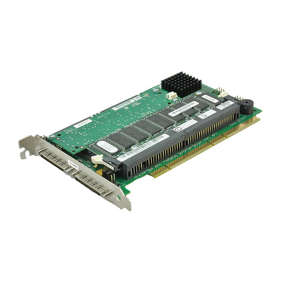
- Page 1 Dell™ PowerEdge Expandable RAID Controller 3/QC, 3/DC, 3/DCL and 3/SC PERC 3 User’s Guide w w w . d e l l . c o m | s u p p o r t . d e l l . c o m...
- Page 2 Reproduction in any manner whatsoever without the written permission of Dell Computer Corporation is strictly forbidden. Trademarks used in this text: Dell, the DELL logo, PowerEdge, PowerVault, and Dell OpenManage are trademarks and DellWare is a registered service mark of Dell Computer Corporation. MegaRAID is a registered trademark of LSI Logic Corporation.
-
Page 3: Safety Instructions
Safety Instructions CAUTION: Safety Instructions Use the following safety guidelines to help ensure your own personal safety and to help protect your computer and working environment from potential damage. General • Do not attempt to service the computer yourself unless you are a trained service technician. - Page 4 • To help protect your computer from sudden, transient increases and decreases in electrical power, use a surge suppressor, line conditioner, or uninterruptible power supply (UPS). • Ensure that nothing rests on your computer’s cables and that the cables are not located where they can be stepped on or tripped over. •...
- Page 5 Before you open the computer cover, perform the following steps in the sequence indicated. CAUTION: Do not attempt to service the computer yourself, except as explained in your online Dell™ documentation or in instructions otherwise provided to you by Dell. Always follow installation and service instructions closely.
- Page 6 • When you disconnect a cable, pull on its connector or on its strain- relief loop, not on the cable itself. Some cables have a connector with locking tabs; if you are disconnecting this type of cable, press in on the locking tabs before disconnecting the cable.
- Page 7 Ergonomic Computing Habits CAUTION: Improper or prolonged keyboard use may result in injury. CAUTION: Viewing the monitor screen for extended periods of time may result in eye strain. Battery Disposal Do not dispose of the battery along with household waste. Contact your local waste disposal agency for the address of the nearest battery deposit site.
-
Page 9: Table Of Contents
Contents Safety Instructions ......1 Overview PERC 3 Overview ......PERC 3 Features . - Page 10 Parity ......Hot Spares ......Disk Rebuilds .
- Page 11 PERC 3/SC Specifications ..... PCI Bridge/CPU ......Cache Memory .
- Page 12 SCSI Firmware ......RAID Management ..... . 6 PERC 3/QC Features Hardware Requirements .
- Page 13 Physical Device Layout ..... . Configuring Arrays ......Arranging Arrays .
- Page 14 Step 5—Install PERC 3/SC ....Step 6—Connect SCSI Cables ....Step 7—Set Target IDs .
- Page 15 Optional Equipment ..... . PERC 3/QC Card Layout ..... . Installation Steps .
- Page 16 Management Menu Options ....Using Dell Manager in Red Hat Linux GUI Mode ..Conte n ts...
- Page 17 Dell Manager Menu Options ....Initialize Menu ......
- Page 18 14 Appendix A: SCSI Cables and Connectors 15 Appendix B: Warranties and Return Policy Glossary ....... . Index .
- Page 19 Figures Figure 2-1. Example of Disk Striping ....Figure 2-2. Example of Disk Mirroring ....Figure 2-3.
- Page 20 F i g u re s...
- Page 21 Tables Table 1-1. Maximum Cable Length for SCSI Standards ..Table 1-2. SCSI Bus Widths and Maximum Throughput ..Table 2-1. Spanning for RAID 10 and RAID 50 ..Table 2-2.
- Page 22 Table 6-3. Hardware Architecture Features ... . . Table 6-4. Array Performance Features ....Table 6-5. Fault Tolerance Features .
- Page 23 Table 11-10. Rebuild Types ....Table 12-1. Command Used to Start Dell Manager ..
- Page 24 Table 12-9. Rebuild Types ....Table 13-1. General Problems and Suggested Solutions ..Table 13-2. BIOS Boot Error Messages .
-
Page 25: Overview
S E C T I O N 1 O v e r v i e w PERC 3 Overview PERC 3 Features... -
Page 26: Perc 3 Overview
PERC 3 Overview The Dell™ PowerEdge™ Expandable RAID Controller 3 (PERC 3) PCI card is a high-performance, intelligent peripheral component interconnect (PCI)-to-SCSI host adapter with RAID control capabilities. PERC 3 provides system availability, high performance, and fault-tolerant disk subsystem management. PERC 3 is an ideal RAID solution for the internal storage of Dell’s workgroup, departmental, and enterprise systems. -
Page 27: Scsi Channels
Battery backup for up to 72 hours for the PERC 3/QC and PERC 3/DC • Up to 12 SCSI drives per channel using the Dell PowerVault 21xS NOTE: Clustering is not storage system or 14 SCSI drives using the Dell PowerVault 22xS supported by PERC 3/QC or PERC 3/DCL. -
Page 28: Single-Ended And Lvd Scsi Buses
PERC 3/SC has one ultra-high-density 68-pin external connector for the external storage subsystem and one high-density 68-pin internal connector. Single-Ended and LVD SCSI Buses The SCSI standard defines two electrical buses: a single-ended bus and an LVD bus. PERC 3 supports both standards. Maximum Cable Length for SCSI Standards Table 1-1 displays the maximum length of cable that you can use for various SCSI standards. -
Page 29: Operating System Support
Ta b l e 1 - 2 . S C S I B u s W i d t h s a n d M a x i m u m T h r o u g h p u t SCSI Standard SCSI Bus Width SCSI Throughput... - Page 30 Ov e r v ie w...
-
Page 31: Introduction To Raid
S E C T I O N 2 I n t r o d u c t i o n t o R A I D RAID Definition PERC 3 Host-Based RAID Solution Components and Features... -
Page 32: Raid Definition
RAID Definition RAID is an array of multiple independent hard disk drives that provides high performance and fault tolerance. The RAID array appears to the host computer as a single storage unit or as multiple logical units. Input/output (I/O) improves because several disks can be accessed simultaneously. Although hard drive capabilities have improved drastically, actual performance has improved only three to four times in the last decade. -
Page 33: Components And Features
• The number of SCSI channels and SCSI hard drives Components and Features RAID versions, or levels, are specifications that describe a system for ensuring the availability and stability of data stored on large disk subsystems. A RAID system can be implemented in a number of different levels). -
Page 34: Consistency Check
A hot spare is an unused online disk that, in case of a disk failure in a redundant RAID array, can be used to rebuild the data and re-establish redundancy. After the hot spare is automatically moved into the RAID subsystem, the failed drive is automatically rebuilt on the spare drive. -
Page 35: Figure 2-1. Example Of Disk Striping
F i g u r e 2 - 1 . E x a m p l e o f D i s k S t r i p i n g Segment 1 Segment 2 Segment 3 Segment 4 Segment 5 Segment 6 Segment 7 Segment 8... -
Page 36: Disk Mirroring
Disk Mirroring With mirroring (used in RAID 1), data written to one disk is simultaneously written to another disk. If one disk fails, the contents of the other disk can be used to run the system and reconstruct the failed disk. The primary advantage of disk mirroring is that it provides 100% data redundancy. -
Page 37: Disk Spanning
Disk Spanning Disk spanning allows multiple physical drives to function like one big drive. Spanning overcomes lack of disk space and simplifies storage management by combining existing resources or adding relatively inexpensive resources. For example, four 20 GB drives can be combined to appear to the operating system as a single 80 GB drive. -
Page 38: Spanning For Raid 10 Or Raid 50
Spanning for RAID 10 or RAID 50 Table 2-1 describes how to configure RAID 10 and RAID 50 by spanning. NOTE: Spanning two Ta b l e 2 - 1 . S p a n n i n g f o r R A I D 1 0 a n d R A I D 5 0 contiguous RAID 0 logical drives does not Level... -
Page 39: Hot Spares
F i g u r e 2 - 4 . E x a m p l e o f P a r i t y Parity Generator Hot Spares A hot spare is an extra, unused disk drive that is part of the disk subsystem. It is usually in standby mode, ready for service if a drive fails. -
Page 40: Disk Rebuilds
There are two types of hot spares: NOTE: Refer to Chapter 11 "PERC 3 BIOS • Global Hot Spare Configuration Utility" for the procedures used to • Dedicated Hot Spare designate a drive as a hot spare. Global Hot Spare A global hot spare drive can be used to replace any failed drive in a redundant array as long as its capacity is equal to or larger than the coerced capacity of the failed drive. -
Page 41: Hot Swap
Rebuilding can be done only in arrays with data redundancy, which includes as RAID 1, 5, 10 and 50. A hot spare can be used to rebuild disk drives in RAID 1, 5, 10, or 50 systems. If a hot spare is not available, the failed disk drive must be replaced with a new disk drive so that the data on the failed drive can be rebuilt. -
Page 42: Logical Drive States
Ta b l e 2 - 3 . S C S I D r i v e S t a t e s (continued) State Description Ready The drive is functioning normally but is not part of a configured logical drive and is not designated as a hot spare. (READY) Hot Spare The drive is powered up and ready for use as a spare in case an... - Page 43 S E C T I O N 3 R A I D L e v e l s Overview Selecting a RAID Level RAID 0 RAID 1 RAID 5 RAID 10 RAID 50...
-
Page 44: Raid Levels
Overview There are six official RAID levels (RAID 0 through RAID 5.) PERC 3 supports RAID levels 0, 1, 5, 10, and 50. The RAID levels that PERC 3 supports are shown in Table 3-1. Ta b l e 3 - 1 . R A I D L e v e l s RAID Type Level... -
Page 45: Raid 0
RAID 0 RAID 0 provides disk striping across all drives in the RAID subsystem. RAID 0 does not provide any data redundancy, but does offer the best performance of any RAID level. RAID 0 breaks up data into smaller blocks and then writes a block to each drive in the array. -
Page 46: Figure 3-1. Raid 0 Array
Figure 3-1 displays an example of a RAID 0 array. F i g u r e 3 - 1 . R A I D 0 A r r a y Segment 1 Segment 2 Segment 3 Segment 4 Segment 5 Segment 6 Segment 7 Segment 8... -
Page 47: Raid 1
RAID 1 In RAID 1, the RAID controller duplicates all data from one drive to a second drive. RAID 1 provides complete data redundancy, but at the cost of doubling the required data storage capacity, as shown in Figure 3-2. Table 3- 3 provides an overview of RAID 1. -
Page 48: Raid 5
F i g u r e 3 - 2 . R A I D 1 A r r a y Segment 1 Segment 1 Duplicated Segment 2 Segment 2 Duplicated Segment 3 Segment 3 Duplicated Segment 4 Segment 4 Duplicated RAID 5 RAID 5 includes disk striping at the block level and parity. -
Page 49: Table 3-4. Raid 5 Overview
Ta b l e 3 - 4 . R A I D 5 O v e r v i e w Uses RAID 5 provides high data throughput, especially for large files. Use RAID 5 for transaction processing applications because each drive can read and write independently. -
Page 50: Raid 10
Figure 3-3 displays an example of a RAID 5 array. F i g u r e 3 - 3 . R A I D 5 A r r a y Data Flow Disk 1 Disk 2 Disk 3 Disk 4 Disk 5 Disk 6 Segment 1... -
Page 51: Table 3-5. Raid 10 Overview
Ta b l e 3 - 5 . R A I D 1 0 O v e r v i e w Uses RAID 10 works best for data storage that needs 100% redundancy of mirrored arrays and that also needs the enhanced I/O performance of RAID 0 (striped arrays.) RAID 10 works well for medium-sized databases or any environment that requires a higher degree of fault... -
Page 52: Raid 50
F i g u r e 3 - 4 . R A I D 1 0 A r r a y Data Flow RAID 1 RAID 1 Disk 1 Disk 2 Disk 3 Disk 4 Segment 1 Segment 1 Segment 2 Segment 2 Segment 3 Segment 3... -
Page 53: Table 3-6. Raid 50 Overview
RAID 50 can sustain one to four drive failures while maintaining data integrity if each failed disk is in a different RAID 5 array. Table 3-6 provides an overview of RAID 50. Ta b l e 3 - 6 . R A I D 5 0 O v e r v i e w Uses RAID 50 works best when used with data that requires high reliability, high request rates, and high data... -
Page 54: Figure 3-5. Raid 50 Array
Figure 3-5 displays an example of a RAID 50 array. F i g u r e 3 - 5 . R A I D 5 0 A r r a y Data Flow RAID 5 RAID 5 Disk 4 Disk 5 Disk 6 Disk 1 Disk 2... -
Page 55: Perc 3/Sc Features
S E C T I O N 4 P E R C 3 / S C Fe a t u r e s Hardware Requirements Configuration Features Hardware Architecture Features Array Performance Features PERC 3/SC Fault Tolerance Features Software Utilities Operating System Software Drivers PERC 3/SC Specifications... -
Page 56: Hardware Requirements
160 MB/s. The SCSI channel supports up to 15 Wide devices or up to seven narrow devices. PERC 3/SC can be installed in a Dell™ PowerEdge™ computer with a motherboard that has 5 V, 32- or 64-bit PCI expansion slots. The computer ®... -
Page 57: Smart Technology
Ta b l e 4 - 1 . C o n f i g u r a t i o n Fe a t u r e s (continued) Specification Feature Non-disk devices supported Mixed capacity hard disk drives Number of 16-bit internal connectors SMART Technology The PERC 3/SC self-monitoring analysis and reporting technology (SMART) detects predictable drive failures. -
Page 58: Hardware Architecture Features
Ta b l e 4 - 2 . C o n f i g u r a t i o n o n D i s k Fe a t u r e s (continued) Specification Feature User-specified rebuild rate Hardware Architecture Features The PERC 3/SC hardware architecture features are shown in Table 4-3. -
Page 59: Perc 3/Sc Fault Tolerance Features
Ta b l e 4 - 4 . A r r a y P e r f o r m a n c e Fe a t u r e s (continued) Specification Feature Maximum scatter/gathers 26 elements Maximum size of I/O requests 6.4 MB in 64 KB stripes Maximum queue tags per drive As many as the drive can accept. -
Page 60: Operating System Software Drivers
Ta b l e 4 - 6 . S o f t w a r e U t i l i t i e s Fe a t u r e s (continued) Specification Feature Bootup configuration using the PERC BIOS configuration utility (Ctrl–M) Online read, write, and cache policy switching Intranet support... -
Page 61: Pci Bridge/Cpu
Ta b l e 4 - 7 . P E R C 3 / S C S p e c i f i c a t i o n s (continued) Parameter Specification SCSI controller One SCSI controller for 160M and Wide support SCSI data transfer rate Up to 160 MB/s per channel SCSI bus... -
Page 62: Perc 3/Sc Bios
PERC 3/SC BIOS The BIOS resides on a 1 MB × 8 flash ROM for easy upgrade. The PERC 3/SC BIOS supports INT 13h calls to boot DOS without special software or device drivers. The PERC 3/SC BIOS provides an extensive setup utility that can be accessed by pressing <Ctrl>... -
Page 63: Scsi Firmware
Dell Manager • WebBIOS Configuration Utility • Dell™ OpenManage™ Array Manager PERC 3 BIOS Configuration Utility You can use the PERC 3 BIOS Configuration Utility to configure and maintain RAID arrays, format disk drives, and manage the RAID system. It is independent of any operating system. - Page 64 Dell Manager is a character-based, non-GUI utility that changes policies and parameters, and monitors RAID systems. Dell Manager runs under Novell NetWare 5.x, 6.x, and Red Hat Linux 7.x. See Chapter 12 "Dell Manager" for additional information. WebBIOS Configuration Utility WebBIOS is used to configure and manage a RAID system using an HTML interface.
- Page 65 S E C T I O N 5 P E R C 3 / D C a n d P E R C 3 / D C L Fe a t u r e s Hardware Requirements Configuration Features Hardware Architecture Features Array Performance Features Fault Tolerance Features Software Utilities...
-
Page 66: Perc 3/Dc And Perc 3/Dcl Features
Multiple logical drives/arrays per Up to 40 logical drives per controller controller Maximum number of PERC 3/DC and Contact your Dell™ representative. PERC 3/DCL controllers per system Online capacity expansion Dedicated and pool hot spare PERC 3/ DC and PE RC 3 /DCL Fe atures... -
Page 67: Smart Technology
Ta b l e 5 - 1 . C o n f i g u r a t i o n Fe a t u r e s (continued) Specification Feature Flashable firmware Hot swap devices supported Non-disk devices supported Mixed capacity hard disk drives Number of 16-bit internal connectors Cluster support... -
Page 68: Hardware Architecture Features
Ta b l e 5 - 2 . C o n f i g u r a t i o n o n D i s k Fe a t u r e s (continued) Specification Feature More than 200 qtags per array Hardware clustering support on the board User-specified rebuild rate Hardware Architecture Features... -
Page 69: Array Performance Features
Array Performance Features Table 5-4 displays the PERC 3/DC and PERC 3/DCL array performance features. Ta b l e 5 - 4 . A r r a y P e r f o r m a n c e Fe a t u r e s Specification Feature Host data transfer rate... -
Page 70: Software Utilities
Software Utilities Table 5-6 lists the software utilities. Ta b l e 5 - 6 . S o f t w a r e U t i l i t i e s Specification Feature Graphical user interface (GUI) Management utility Bootup configuration using BIOS Configuration Utility (Ctrl–M) Online read, write, and cache policy switching... -
Page 71: Pci Bridge/Cpu
Ta b l e 5 - 7 . P E R C 3 / D C a n d P E R C 3 / D C L S p e c i f i c a t i o n s Parameter Specification Cache configuration... -
Page 72: Cache Memory
Cache Memory Either 64 MB or 128 MB of PERC 3/DC and PERC 3/DCL cache memory reside in a memory bank that uses a 64 MB or 128 MB SDRAM DIMM. PERC 3/DC and PERC 3/DCL support write-through or write-back caching, selectable for each logical drive. -
Page 73: Scsi Connectors
SCSI Connectors The PERC 3/DC and PERC 3/DCL adapter has two types of SCSI connectors: • Two 68-pin high density internal connectors • Two 68-pin external ultra-high-density connectors Only one connector type can be used for the SCSI channel at any one time. SCSI Termination PERC 3/DC and PERC 3/DCL uses active termination on the SCSI bus conforming to SCSI-2 and SCSI-3 specifications. -
Page 74: Raid Management
Dell Manager is a character-based, non-GUI utility that changes policies, and parameters, and monitors RAID systems. Dell Manager runs under Novell NetWare 5.x, 6.x, and Red Hat Linux 7.x. See Chapter 12 "Dell Manager" for additional information. WebBIOS Configuration Utility WebBIOS is used to configure and manage a RAID system using an HTML interface. -
Page 75: Perc 3/Qc Features
S E C T I O N 6 P E R C 3 / Q C Fe a t u r e s Hardware Requirements Configuration Features Hardware Architecture Features Array Performance Features Fault Tolerance Features Software Utilities Operating System Software Drivers PERC 3/QC Specifications... -
Page 76: Hardware Requirements
Multiple logical drives/arrays per Up to 40 logical drives per controller controller Maximum number of PERC 3/QC Contact your Dell™ representative. controllers per system Online capacity expansion Dedicated and pool hot spare Flashable firmware PERC 3/ QC Feat ures... -
Page 77: Smart Technology
Ta b l e 6 - 1 . C o n f i g u r a t i o n Fe a t u r e s (continued) Specification Feature Hot swap devices supported Non-disk devices supported Mixed-capacity hard drives Number of 16-bit internal connectors SMART Technology NOTE: The PERC 3/QC... -
Page 78: Hardware Architecture Features
Ta b l e 6 - 2 . C o n f i g u r a t i o n o n D i s k Fe a t u r e s (continued) Specification Feature User-specified rebuild rate Hardware Architecture Features Table 6-3 lists the PERC 3/QC hardware architecture features. -
Page 79: Fault Tolerance Features
Ta b l e 6 - 4 . A r r a y P e r f o r m a n c e Fe a t u r e s (continued) Specification Feature Drive data transfer rate 160 MB/s Maximum scatter/gathers 26 elements Maximum size of I/O requests... -
Page 80: Operating System Software Drivers
Ta b l e 6 - 6 . S o f t w a r e U t i l i t i e s Specification Feature Graphical user interface Management utility Bootup configuration using PERC BIOS configuration utility (Ctrl–M) Online read, write, and cache policy switching Intranet support Operating System Software Drivers... -
Page 81: Pci Bridge/Cpu
Ta b l e 6 - 7 . P E R C 3 / Q C S p e c i f i c a t i o n s (continued) Parameter Specification Operating voltage 5 V, 3.3 V SCSI controller Four SCSI controllers for 160M and Wide support. -
Page 82: Perc 3/Qc Bios
PERC 3/QC BIOS The BIOS resides on a 1 MB × 8 flash ROM for easy upgrade. The PERC 3/QC BIOS supports INT 13h calls to boot DOS without special software or device drivers. The PERC 3/QC BIOS provides an extensive setup utility that can be accessed by pressing <Ctrl>... -
Page 83: Scsi Firmware
Dell Manager • WebBIOS Configuration Utility • Dell™ OpenManage™ Array Manager PERC 3 BIOS Configuration Utility You can use the PERC 3 BIOS Configuration Utility to configure and maintain RAID arrays, format disk drives, and manage the RAID system. It is independent of any operating system. - Page 84 Dell Manager is a character-based, non-GUI utility that changes policies, and parameters, and monitors RAID systems. Dell Manager runs under Novell NetWare 5.x, 6.x, and Red Hat Linux 7.x. See Chapter 12 "Dell Manager" for additional information. WebBIOS Configuration Utility WebBIOS is used to configure and manage a RAID system using an HTML interface.
-
Page 85: C O N F I G U R I N G P E R C 3
S E C T I O N 7 C o n f i g u r i n g P E R C 3 Configuring SCSI Physical Drives Current Configuration Logical Drive Configuration Physical Device Layout Configuring Arrays Configuration Strategies Assigning RAID Levels Configuring Logical Drives Optimizing Data Storage... -
Page 86: Configuring Scsi Physical Drives
Configuring SCSI Physical Drives Physical SCSI drives must be organized into logical drives. The arrays and logical drives that you construct must be able to support the RAID) level that you select. Observe the following guidelines when connecting and configuring SCSI devices in a RAID array: •... -
Page 87: Table 7-1. Current Configuration For Scsi Channel 0
Ta b l e 7 - 1 . C u r r e n t C o n f i g u r a t i o n f o r S C S I C h a n n e l 0 (continued) SCSI ID Device Description SCSI Channel 0... -
Page 88: Table 7-3. Current Configuration For Scsi Channel
Ta b l e 7 - 2 . C u r r e n t C o n f i g u r a t i o n f o r S C S I C h a n n e l 1 (continued) SCSI ID Device Description SCSI Channel 1... -
Page 89: Logical Drive Configuration
Use Table 7-4 to list the devices that you assign to each SCSI ID for SCSI Channel 3. Ta b l e 7 - 4 . C u r r e n t C o n f i g u r a t i o n f o r S C S I C h a n n e l 3 SCSI ID Device Description... - Page 90 Logical RAID Stripe Logical Cache Read Write # of Physical Drive Size Drive Size Policy Policy Policy Drives LD10 LD11 LD12 LD13 LD14 LD15 LD16 LD17 LD18 LD19 LD20 LD21 LD22 LD23 LD24 LD25 LD26 LD27 LD28 LD29 LD30 Confi gur ing PERC 3...
-
Page 91: Physical Device Layout
Logical RAID Stripe Logical Cache Read Write # of Physical Drive Size Drive Size Policy Policy Policy Drives LD31 LD32 LD33 LD34 LD35 LD36 LD37 LD38 LD39 Physical Device Layout Use Table 7-6 to list the details for each physical device on the channels. Ta b l e 7 - 6 . - Page 92 Ta b l e 7 - 6 . P h y s i c a l D e v i c e L a y o u t (continued) Channel 0 Channel 1 Channel 2 Channel 3 Device type Logical drive number/ Drive number Manufacturer/Model number...
- Page 93 Ta b l e 7 - 6 . P h y s i c a l D e v i c e L a y o u t (continued) Channel 0 Channel 1 Channel 2 Channel 3 Manufacturer/Model number Firmware level Target ID Device type Logical drive number/...
-
Page 94: Configuring Arrays
Ta b l e 7 - 6 . P h y s i c a l D e v i c e L a y o u t (continued) Channel 0 Channel 1 Channel 2 Channel 3 Device type Logical drive number/ Drive number Manufacturer/Model number... -
Page 95: Arranging Arrays
Arranging Arrays You must arrange the arrays to provide additional organization for the drive array. You must arrange arrays so that you can create system drives that can function as boot devices. You can sequentially arrange arrays with an identical number of drives so that the drives in the group are spanned. -
Page 96: Maximizing Capacity
Maximizing Capacity RAID 0 achieves maximum drive capacity, but does not provide data redundancy. Maximum drive capacity for each RAID level is shown below. original equipment manufacturer (OEM) level firmware that can span up to four logical drives is assumed. Table 7-7 displays the drives required, and capacity for the various RAID levels. -
Page 97: Maximizing Drive Performance
Ta b l e 7 - 8 . Fa u l t To l e r a n c e Fe a t u r e s f o r R A I D L e v e l s 0 , 1 a n d 5 (continued) RAID Fault Tolerance Protection... -
Page 98: Configuring Logical Drives
Ta b l e 7 - 1 0 . P h y s i c a l D r i v e s R e q u i r e d f o r E a c h R A I D L e v e l RAID Minimum Number of Maximum Number of Physical... -
Page 99: Array Functions
Servers that support Video on Demand typically read the data often, but write data infrequently. Both the read and write operations tend to be long. Data stored on a general-purpose file server involves relatively short read and write operations with relatively small files. Array Functions You must first define the major purpose of the disk array. -
Page 100: Using The Array Configuration Planner
Using the Array Configuration Planner Table 7-12 lists RAID levels, fault tolerance, and effective capacity for some possible drive configurations for an array consisting of one to 32 drives. This table does not take into account any hot spare (standby) drives. You should always have a hot spare drive in case of drive failure. -
Page 101: Random Array Deletion
Ta b l e 7 - 1 2 . A r r a y C o n f i g u r a t i o n P l a n n e r (continued) Number Possible RAID Relative Fault Effective of Drives Levels... -
Page 102: Configuration Module
After you delete a logical drive, you can create a new one. You can use the NOTE: When a ‘delete’ request reaches the configuration utilities to create the next logical drive from the non- operating system driver, contiguous free space (‘holes’), and from the newly created arrays. The the driver stops all the configuration utility provides a list of configurable arrays where there is a running input/output (I/O) -
Page 103: Perc 3/Sc Hardware Installation
S E C T I O N 8 P E R C 3 / S C H a r d w a r e I n s t a l l a t i o n Requirements PERC 3/SC Card Layout Installation Steps... -
Page 104: Requirements
SCSI devices to be attached.) • Fast, Ultra, Ultra II, and 160M SCSI hard drives Dell™ strongly recommends that you have an uninterruptible power supply (UPS) for the entire system. Optional Equipment You may also want to install SCSI cables that connect the PERC 3/SC to external SCSI devices. -
Page 105: Perc 3/Sc Card Layout
Unpack the PERC 3/SC controller and inspect for damage. Make sure all items are in the package. If damaged, call your Dell™ original equipment manufacturer (OEM) support representative. Turn the computer off and remove the cover. -
Page 106: Step 1-Unpack
Remove the controller card and inspect it for damage. If the card appears damaged, or if any item listed below is missing, contact your Dell support representative. The PERC 3 controller also comes with: •... -
Page 107: Step 3-Set Jumpers
Step 3—Set Jumpers Make sure the jumper settings on the PERC 3/SC card are correct. The jumpers and connectors are shown in Table 8-1. Ta b l e 8 - 1 . P E R C 3 / S C J u m p e r s Connector Description Type... -
Page 108: Table 8-3. J9 I2C Interface Connector Pinout
Ta b l e 8 - 2 . J 1 Te r m i n a t i o n E n a b l e S e t t i n g s (continued) Type of SCSI Termination J10 Setting Permanently disable all onboard SCSI termination. -
Page 109: Table 8-5. J8 Hard Disk Led
J8 Hard Disk LED J8 is a four-pin connector that attaches to a cable that connects to the hard disk light emitting diode (LED) mounted on the computer enclosure. The LED indicates data transfers.Table 8-5 shows the pinout for J8. Ta b l e 8 - 5 . -
Page 110: Step 4-Set Scsi Termination
J16, J17 RUBI Slot Interrupt Steering J16 and J17 are 3-pin jumpers. You can short them for a one-channel or two- channel motherboard. The default is OPEN; the pins are not shorted. Table 8-7 shows the settings for shorting J16 and J17. Ta b l e 8 - 7 . - Page 111 SCSI Termination The SCSI bus is an electrical transmission line and it must be terminated properly to minimize reflections and losses. You complete the SCSI bus by setting termination at both ends. You can let PERC 3/SC automatically provide SCSI termination at one end of the SCSI bus.
-
Page 112: Figure 8-3. Termination Of Internal Scsi Disk Arrays
F i g u r e 8 - 3 . Te r m i n a t i o n o f I n t e r n a l S C S I D i s k A r r a y s Termination Enabled ID1 –... -
Page 113: Step 5-Install Perc 3/Sc
Step 5—Install PERC 3/SC Choose a 3.3 V or 5 V PCI slot and align the PERC 3/SC card bus connector to the slot. Press down gently but firmly to make sure that the card is properly seated in the slot. The bottom edge of the controller card should be flush with the slot. -
Page 114: Figure 8-5. Installation Of Perc 3/Sc Card Into Motherboard
Insert the PERC 3/SC card in a PCI slot, as shown in Figure 8-5. Screw the bracket to the computer chassis. F i g u r e 8 - 5 . I n s t a l l a t i o n o f P E R C 3 / S C C a r d i n t o M o t h e r b o a r d Bracket Screw 32-bit Slots... -
Page 115: Step 6-Connect Scsi Cables
Step 6—Connect SCSI Cables Connect the SCSI cables to SCSI devices, as shown in Figure 8-6. PERC 3/SC provides two SCSI connectors: • J11, the SCSI channel internal high-density 68-pin connector for Wide (16-bit) SCSI • J13, the SCSI channel external ultra high-density 68-pin connector for Wide (16-bit) SCSI Make sure all cables are properly attached, and that the PERC 3/SC card is properly installed. -
Page 116: Step 7-Set Target Ids
Perform the following steps to connect SCSI devices: Disable termination on any SCSI device that does not sit at the end of the SCSI bus. Configure all SCSI devices to supply termination power (TermPWR.) Set proper target IDs (TIDs) for all SCSI devices. Cable Suggestions System throughput problems can occur if SCSI cable use is not maximized. -
Page 117: Step 8-Power On Host System
During boot, the PERC 3 BIOS message appears: PowerEdge Expandable RAID Controller BIOS Version x.xx date Copyright (c) Dell Computer Corporation Firmware Initializing... [Scanning SCSI Device...(etc.)...] The firmware takes several seconds to initialize. During this time the adapter scans the SCSI channel. When ready, the following appears: HA –0 (Bus 1 Dev 6) Type: PERC 3/SC Standard FW x.xx SDRAM=... -
Page 118: Step 9-Run Perc 3 Bios Configuration Utility Or Webbios Utility
The PERC 3 BIOS Configuration Utility prompt times out after several seconds. The PERC 3 host adapter (controller) number, firmware version, and cache synchronized dynamic random access memory (SDRAM) size display in the second portion of the BIOS message. The numbering of the controllers follows the PCI slot scanning order used by the host motherboard. - Page 119 S E C T I O N 9 P E R C 3 / D C o r P E R C 3 / D C L H a r d w a r e I n s t a l l a t i o n Requirements PERC 3/DC Card Layout PERC 3/DCL Card Layout...
-
Page 120: Requirements
The necessary SCSI cables (This depends on the number and type of SCSI devices to be attached.) • Low-voltage differential (LVD) or 160M SCSI hard drives Dell™ strongly recommends that you have an uninterruptible power supply (UPS) for the entire system. Optional Equipment NOTE: The PERC 3/DC has a battery option;... -
Page 121: Perc 3/Dc Card Layout
PERC 3/DC Card Layout F i g u r e 9 - 1 . P E R C 3 / D C C a r d L a y o u t J4 Channel 0 Internal J5 Channel 1 Internal High-Density 68-pin High-Density 68-pin SCSI Connector... -
Page 122: Perc 3/Dcl Card Layout
PERC 3/DCL Card Layout F i g u r e 9 - 2 . P E R C 3 / D C L C a r d L a y o u t J4 Channel 0 Internal J5 Channel 1 Internal High-Density 68-pin High-Density 68-pin SCSI Connector... -
Page 123: Step 1-Unpack The Perc 3/Dc Or Perc 3/Dcl
Unpack and install the hardware in a static-free environment. Remove the controller card and inspect it for damage. If the card appears damaged, please contact your Dell support representative. Step 2—Power Down Turn off the computer and remove the AC power cord. Ensure that the computer is disconnected from any networks before installing the controller. -
Page 124: Table 9-2. J2 And J3 Termination Enable Settings
Ta b l e 9 - 1 . J u m p e r S e t t i n g s (continued) Connector Description Type Dirty cache (Write Pending) LED 2-pin header SCSI activity LED 4-pin header Channel 1 external Wide SCSI 68-pin connector Channel 0 TERMPWR enable 2-pin header... -
Page 125: Figure 9-3. J11 Serial Port Pinout
J10 NVRAM Clear J10 is a 2-pin connector used to clear the memory from the NVRAM, which stores RAID configuration information. Table 9-4 displays the pinout for J10. Ta b l e 9 - 4 . J 1 0 N V R A M C l e a r P i n o u t Description Signal J11 Serial Port... -
Page 126: Table 9-6. J13 Dirty Cache Led Pinout
Ta b l e 9 - 6 . J 1 3 D i r t y C a c h e L E D P i n o u t Description Signal pulled high Dirty cache signal J14 SCSI Activity LED J14 is a four-pin connector for an LED mounted on the computer enclosure. -
Page 127: Step 4-Set Scsi Termination
J17 I2C Connector J17 is a 4-pin header. Table 9-9 displays the J17 pinout. Ta b l e 9 - 9 . J 1 7 I 2 C C o n n e c t o r P i n o u t Description Data Clock... -
Page 128: Step 5-Install The Perc 3/Dc Or Perc 3/Dcl Controller
F i g u r e 9 - 4 . Te r m i n a t i o n o f I n t e r n a l S C S I D i s k A r r a y s f o r P E R C 3 / D C a n d 3 / D C L Internal SCSI Drives Boot Drive... -
Page 129: Figure 9-5. Installation Of The Perc 3/Dc And 3/Dcl
F i g u r e 9 - 5 . I n s t a l l a t i o n o f t h e P E R C 3 / D C a n d 3 / D C L Bracket Screw 32-bit Slots (5 V) -
Page 130: Step 6-Select And Set Target Ids For Scsi Devices
Step 6—Select and Set Target IDs for SCSI Devices Set target identifiers (TIDs) on the SCSI devices. Each device in a specific SCSI channel must have a unique TID in that channel. See the documentation for each SCSI device to set the TIDs. The PERC 3/DC or PERC 3/DCL controller automatically occupies TID 7 in the SCSI channel. -
Page 131: Figure 9-6. Connecting Scsi Cables To Perc 3/Dc And 3/Dcl
The cable length should not exceed 12 meters for LVD and 160M SCSI devices. Cable Suggestions SCSI disk subsystem throughput can impaired if SCSI cabling is not optimized. Dell suggests using the following: • Actively terminated cables • Dell-approved cables... -
Page 132: Step 8-Power On Host System
PERC 3/DC message is shown.) PowerEdge Expandable RAID Controller BIOS Version xwxx date Copyright (c) Dell Computer Corporation Firmware Initializing... [Scanning SCSI Device...(etc.)...] The firmware takes several seconds to initialize. During this time the adapter will scan the SCSI channel. When ready, the following appears: HA –0 (Bus 1 Dev 6) Type: PERC 3/DC Standard FW xwxx SDRAM=... -
Page 133: Step 10-Install Operating System Software Driver
Step 10—Install Operating System Software Driver See the documentation for the PERC 3/DC or PERC 3/DCL operating systems driver for additional information about installing the drivers for Windows NT, Windows 2000, Novell NetWare 5.x, 6.x, and Red Hat Linux 7.x. Replacing a PERC 3/DC Containing a BC Chip with a PERC 3/DC Containing a BE Chip... - Page 134 Upgrade the existing driver from 5.22.1 or 5.22.2 to 5.30 or later. Shut down the machine in which you are going to replace the controller. Replace the controller (using the procedures in this chapter.) Boot to Windows. When you log into Windows, New Device Prompts appears. Load the driver if prompted.
-
Page 135: Perc 3/Qc Hardware Installation
S E C T I O N 1 0 P E R C 3 / Q C H a r d w a r e I n s t a l l a t i o n Requirements PERC 3/QC Card Layout Installation Steps... -
Page 136: Requirements
SCSI devices to be attached.) • Fast, Ultra, Ultra II, and 160M SCSI hard drives Dell™ strongly recommends that you have an uninterruptible power supply (UPS) for the entire system. Optional Equipment You may also want to install SCSI cables that connect PERC 3/QC to external SCSI devices. -
Page 137: Perc 3/Qc Card Layout
PERC 3/QC Card Layout Figure 10-1 displays the PERC 3/QC card and jumpers. F i g u r e 1 0 - 1 . P E R C 3 / Q C C a r d L a y o u t PE RC 3/ QC Har d war e In s ta l lati on... -
Page 138: Installation Steps
Unpack the PERC 3/QC controller and inspect for damage. Make sure all items are in the package. If damaged, call your Dell original equipment manufacturer (OEM) support representative. Turn the computer off and remove the cover. -
Page 139: Step 2-Power Down
Step 2—Power Down Turn off the computer and remove the cover. Make sure the computer is turned off and disconnected from any networks before installing the controller. Step 3—Set Jumpers Make sure the jumper settings on the PERC 3/QC card are correct. Table 10-1 displays the jumpers and connectors. -
Page 140: Table 10-2. J2, J3, J5 And J7 Termination Enable Pinout
J2, J3, J5, and J7 Termination Enable J2, J3, J5, and J7 are 3-pin connectors that set the SCSI termination for each SCSI channel. The Dell default is termination always enabled (OPEN.) Table 10-2 displays the pinout. Ta b l e 1 0 - 2 . J 2 , J 3 , J 5 a n d J 7 Te r m i n a t i o n E n a b l e P i n o u t... -
Page 141: Figure 10-2. J14 Serial Port Diagram
J14 Serial Port J14 attaches to a serial cable. Figure 10-2 and Table 10-4 show the pinout for J14. F i g u r e 1 0 - 2 . J 1 4 S e r i a l P o r t D i a g r a m 2 4 6 8 1 3 5 7 9 Ta b l e 1 0 - 4 . -
Page 142: Step 4-Set Scsi Termination
SCSI cable(s), as shown below. Termination is always enabled, regardless of the configuration. However, you can override this setting by setting another state. The Dell default is termination by jumper. Figure 10-3 displays an example of termination. -
Page 143: Scsi Termination
F i g u r e 1 0 - 3 . E x a m p l e o f Te r m i n a t i o n SCSI Terminator Termination on Controller SCSI Devices Enabled (Termination Disabled on Both) For a disk array, set SCSI bus termination so that removing or adding a SCSI device does not disturb termination. -
Page 144: Figure 10-4. Termination Of Internal Scsi Disk Arrays
Terminating Internal SCSI Disk Arrays Set the termination so that SCSI termination and termination power are intact when any disk drive is removed from a SCSI channel, as shown in Figure 10-4. F i g u r e 1 0 - 4 . Te r m i n a t i o n o f I n t e r n a l S C S I D i s k A r r a y s Internal SCSI Drives Boot Drive No Termination... -
Page 145: Step 5-Install Perc 3/Qc
Step 5—Install PERC 3/QC Choose a 3.3 V or 5 V PCI slot and align the PERC 3/QC bus connector to the slot. Press down gently but firmly to make sure that the card is properly seated in the slot. The bottom edge of the controller card should be flush with the slot. -
Page 146: Figure 10-6. Installation Of The Perc 3/Qc Card
Insert the PERC 3/QC card into a PCI slot as shown in Figure 10-6. Screw the bracket to the computer frame. F i g u r e 1 0 - 6 . I n s t a l l a t i o n o f t h e P E R C 3 / Q C C a r d Bracket Screw 32-bit Slots (3.3 V) -
Page 147: Step 6-Connect Scsi Cables
Step 6—Connect SCSI Cables Connect SCSI cables to SCSI devices. PERC 3/QC provides two internal SCSI connectors, J1 (channel 1) and J4 (channel 0), which are the SCSI channel internal high-density 68-pin connectors for Wide (16-bit) SCSI. PERC 3/QC provides four external SCSI connectors: J13 (channels 0 and 1) and J22 (channels 2 and 3), the SCSI channel external ultra high-density 68-pin connectors for Wide (16-bit) SCSI. -
Page 148: Step 7-Set Target Ids
SCSI device, the device might not be recognized. During boot, the PERC 3/QC BIOS message appears: PowerEdge Expandable RAID Controller BIOS Version x.xx date Copyright (c) Dell Computer Corporation PERC 3/ QC H a r d war e Ins ta l lati on... -
Page 149: Step 9-Run The Perc 3 Bios Configuration Utility Or Webbios Configuration Utility
Firmware Initializing... [Scanning SCSI Device...(etc.)...] The firmware takes several seconds to initialize. During this time the adapter will scan the SCSI channel. When ready, the following appears: HA –0 (Bus 1 Dev 6) Type: PERC 3/QC Standard FW x.xx SDRAM= xxxMB Battery Module is Present on Adapter 0 Logical Drives found on the Host Adapter... - Page 150 PERC 3/ QC H a r d war e Ins ta l lati on...
-
Page 151: Perc 3 Bios Configuration Utility
S E C T I O N 1 1 P E R C 3 B I O S C o n f i g u r a t i o n U t i l i t y Configuration On Disk Starting the PERC 3 BIOS Configuration Utility BIOS Configuration Utility Menu Options Configuring Arrays and Logical Drives... -
Page 152: Configuration On Disk
The PERC 3 BIOS Configuration Utility configures disk arrays and logical drives. Because the utility resides in the PERC 3 BIOS, its operation is independent of the operating systems on your computer. This chapter describes the utility, and the configuration options it offers. Clustering is described at the end of the chapter. -
Page 153: Bios Configuration Utility Menu Options
Press <Ctrl><H> to Enable BIOS For each PERC adapter in the host system, the firmware version, dynamic random access memory (DRAM) size, and the status of logical drives on the card display. If you do not press <Ctrl><M> within a few seconds of the prompt, the computer continues normal booting. -
Page 154: Configure Menu
Ta b l e 1 1 - 1 . B I O S C o n f i g u r a t i o n U t i l i t y M e n u O p t i o n s Option Description Objects... -
Page 155: Initialize Menu
Initialize Menu Choose Initialize from the BIOS Configuration Utility Management Menu NOTE: See page 178 for procedures for initializing to initialize one or more logical drives. Press the space bar to select a single logical drives. driver or the <F2> key to select all drives for initialization. This action typically follows the configuration of a new logical drive. - Page 156 Emulation You can operate in the I2O mode or mass storage mode Dell recommends that you use only mass storage mode, and Dell drivers only. Auto Rebuild Set to Enabled to automatically rebuild drives when they fail.
-
Page 157: Table 11-4. Logical Drive Menu Options
Cluster Mode and the Initiator ID You can enable or disable cluster mode. When you disable cluster mode, the system operates in standard mode. In addition, when you enable cluster mode, the system automatically disables the BIOS. You can change the Initiator ID only when you are in cluster mode. You cannot change the ID while in standard mode. -
Page 158: Table 11-5. Physical Drive Menu Options
Select Enabled to enable Virtual Sizing. After you have created a logical drive set, the partition of the drive should be as large as the virtual size of the logical drive. After you have created a logical array set, the drive partition can be as large as the full size of the logical drive. -
Page 159: Table 11-6. Scsi Channel Menu Options
Channel Choose Objects—> Channel to select a SCSI channel on the currently selected controller. After you select a channel, press <Enter> to display the options for that channel. Table 11-6 describes the SCSI channel menu options. Ta b l e 1 1 - 6 . S C S I C h a n n e l M e n u O p t i o n s Option Description Termination... -
Page 160: Format Menu
Ta b l e 1 1 - 7 . B a t t e r y I n f o r m a t i o n M e n u O p t i o n s (continued) Menu Item Explanation No of Cycles Displays the number of charge cycles. -
Page 161: Check Consistency Menu
Check Consistency Menu Choose Check Consistency to verify the redundancy data in logical drives that use RAID levels 1, 5, 10, and 50. The parameters of the existing logical drives appear. Discrepancies are automatically corrected, assuming always that the data is correct. However, if the failure is a read error on a data drive, the bad data block is reassigned with the generated data. -
Page 162: Choosing The Configuration Method
Choose a configuration method. Designate hot spares (optional). Create arrays using the available physical drives. Define logical drives using the space in the arrays. Save the configuration information. Initialize the new logical drives. Choosing the Configuration Method Easy Configuration In Easy Configuration, each physical array you create is associated with exactly one logical drive, and you can modify the following parameters: •... -
Page 163: View/Add Configuration
If you select New Configuration, the existing configuration information on the selected controller is destroyed when the new configuration is saved. View/Add Configuration View/Add Configuration allows you to control the same logical drive parameters as New Configuration without disturbing the existing configuration information. -
Page 164: Reserved Disk Space During Configuration
Reserved Disk Space during Configuration Up to 20.6 MB of disk space is reserved when a hard drive is being configured. Designating Drives as Hot Spares Hot spares are physical drives that are powered up along with the RAID drives and usually stay in a standby state. The hot spare drive should be larger than or equal to the smallest logical drive. -
Page 165: Using Easy Configuration
Press the arrow keys to select Make HotSpare and press <Enter>. The indicator for the selected drive changes to HOTSP . Save the configuration. Using Easy Configuration In Easy Configuration, each array is associated with exactly one logical drive. Perform the following steps to create arrays using Easy Configuration. - Page 166 Press the arrow keys to highlight specific physical drives. NOTE: Try to use drives of the same capacity in a Press the spacebar to associate the selected physical drive with the specific array. If you use current array. drives with different capacities in an array, all The indicator for the selected drive changes from READY to ONLIN drives in the array are...
- Page 167 NOTE: You can press <F2> to display the number of drives in the array, their channel and ID, and <F3> to display array information, such as the stripes, slots, and free space. Press <F10> to configure logical drives. The logical drive configuration screen appears. Span=Yes displays on this screen if you select two or more arrays to span.
- Page 168 Stripe Size specifies the size of the segments written to each disk in a RAID 1 or 5 logical drive. You can set the stripe size to 2 KB, 4 KB, 8 KB, 16 KB, 32 KB, 64 KB, or 128 KB. A larger stripe size produces better read performance, especially if your computer does mostly sequential reads.
-
Page 169: Using New Configuration
– Direct I/O specifies that reads are not buffered in cache memory. Direct I/O does not override the cache policy settings. Data is transferred to cache and the host concurrently. If the same data block is read again, it comes from cache memory. This is the default setting. - Page 170 An array selection window displays the devices connected to the current controller. Hot key information appears at the bottom of the screen. The hot key functions are: – <F2> Display drive data and PERC 3 error count for the selected drive.
- Page 171 – RAID 50 requires at least six physical drives per array. Press <Enter> after you finish creating the current array. A window entitled Select Configurable Array(s) appears. It displays the array, and array number, such as A-00. Press the spacebar to select the array. Span information, such as Span-1, displays in the array box.
- Page 172 The logical drive configuration screen appears. Span=Yes displays on this screen if you select two or more arrays to span. The window at the top of the screen shows the logical drive that is currently being configured as well as any existing logical drives. The column headings are: –...
- Page 173 the criteria are not met, the span setting makes no difference for the current logical drive. Highlight a spanning option and press <Enter>. Set the logical drive size. Move the cursor to Size and press <Enter>. By default, the logical drive size is set to all available space in the array(s) being associated with the current logical drive, accounting for the span setting.
- Page 174 – No-Read-Ahead specifies that the controller does not use read- ahead for the current logical drive. – Read-ahead specifies that the controller uses read-ahead for the current logical drive. – Adaptive specifies that the controller begins using read-ahead if the two most recent disk accesses occurred in sequential sectors. If all read requests are random, the algorithm reverts to No-Read- Ahead, however, all requests are still evaluated for possible sequential operation.
-
Page 175: Using View/Add Configuration
Using View/Add Configuration View/Add Configuration allows you to associate logical drives with physical arrays (this is called spanning of arrays.) The existing configuration is left intact, so you can also use View/Add Configuration simply to look at the current configuration. Perform the following steps to configure the arrays using View/Add Configuration. - Page 176 The number of physical drives in a specific array determine the RAID levels that can be implemented with the array. – RAID 0 requires one or more physical drives per array. NOTE: Dell does not recommend using RAID 0 – RAID 1 requires two physical drives per array.
- Page 177 NOTE: You can press <F2> to display the number of drives in the array, their channel and ID, and <F3> to display array information, such as the stripes, slots, and free space. Press <F10> to configure a logical drive. The logical drive configuration screen appears. Span=Yes displays on this screen if you select two or more arrays to span.
- Page 178 – CanSpan: Array spanning is enabled for the current logical drive. The logical drive can occupy space in more than one array. – NoSpan: Array spanning is disabled for the current logical drive. The logical drive can occupy space in only one array. PERC 3 supports spanning for RAID 1 and RAID 5 arrays only.
- Page 179 – In Write-back caching, the controller sends a data transfer completion signal to the host when the controller cache has received all the data in a transaction. This setting is not recommended. – In Write-through caching, the controller sends a data transfer completion signal to the host when the disk subsystem has received all the data in a transaction.
-
Page 180: Initializing Logical Drives
If space remains in the arrays, the next logical drive to be configured appears. Repeat steps 3 to 21 to create an array and configure another logical drive. If all array space is used, a list of the existing logical drives appears. Press any key to continue. -
Page 181: Individual Initialization
Individual Initialization Choose Objects—> Logical Drive option from the Management Menu. Select the logical drive to be initialized. Choose Initialize from the action menu. Initialization progress appears as a bar graph on the screen. When initialization completes, press any key to display the previous menu. -
Page 182: Formatting Physical Drives
This deletes the logical drive and makes the space it occupied available for you to make another logical drive. Formatting Physical Drives You can do low-level formatting of SCSI drives using the BIOS Configuration Utility. Because most SCSI disk drives are low-level formatted at the factory, this step is usually not necessary. - Page 183 • Individual Formatting. Choose the Format option from Objects—> Physical Drive action menu for a physical drive. Batch Formatting Select Format from the Management Menu. A device selection window displays the devices connected to the current controller. Press the arrow keys to highlight the drives. Press the spacebar to select the desired physical drives for formatting.
-
Page 184: Rebuilding Failed Disk Drives
Rebuilding Failed Disk Drives If a disk drive fails in an array that is configured as a RAID 1 or 5 logical drive, you can recover the lost data by rebuilding the drive. Table 11-10 describes the types of rebuilds. Ta b l e 1 1 - 1 0 . -
Page 185: Using A Pre-Loaded Scsi Drive "As-Is
A device selection window displays the devices connected to the current controller. The failed drives have FAIL indicators. Press the arrow keys to highlight any failed drives to be rebuilt., Press the spacebar to select the desired physical drives for rebuild. After you select the physical drives, press <F10>. -
Page 186: Exiting The Perc 3 Bios Configuration Utility
Press <Esc> to exit the Advanced Menu. You are prompted to accept the settings. Highlight Accept and press <Enter>. Do not initialize the logical drive. Press <Esc>. and choose Yes at the Save prompt. Exit the BIOS Configuration Utility. Reboot the system. Set the host system to boot from SCSI, if such a setting is available. -
Page 187: Clustering
To enable hardware termination, leave the pins open. The default is hardware termination. Clustering Physically, a cluster is a grouping of two independent servers that can access NOTE: Clustering is not supported by PERC 3/QC, the same data storage and provide services to a common set of clients. With PERC 3/DCL or PERC current technology, this usually means servers connected to common I/O 3/SC. - Page 188 After you start the BIOS configuration utility, perform the following steps to enable or disable the cluster mode: Select Objects—> Adapter—> Cluster Mode. Select Enable or Disable. After you select Disable or Enable, a dialog box displays for you to confirm your choice to change the parameter.
-
Page 189: Dell Manager
S E C T I O N 1 2 D e l l M a n a g e r Starting Dell Manager Dell Manager Menu Options Designating Drives as Hot Spares Parameters Initializing Logical Drives Deleting Logical Drives (Random Array Deletion) -
Page 190: Starting Dell Manager
NetWare 5.x, 6.x, and Red Hat Linux 7.x. To start Dell Manager from any directory, make sure the program file is in the usr/sbin directory. Type the command shown in Table 12-1. Ta b l e 1 2 - 1 . C o m m a n d U s e d t o S t a r t D e l l M a n a g e r In... -
Page 191: Management Menu Options
Reconstruct Select this option to reconstruct an array. Using Dell Manager in Red Hat Linux GUI Mode On a Red Hat Linux system, for Dell Manager to work correctly in a terminal in GUI Mode, you must: • Set the terminal type to linux. -
Page 192: Dell Manager Menu Options
This action typically follows the configuration of a new logical drive. Objects Menu Choose Objects from the Dell Manager Management Menu to access the controllers, logical drives, physical drives, and SCSI channels individually. You can also change certain settings for each object. The Objects menu options are described in Table 12-3. -
Page 193: Table 12-4. Logical Drive Menu Options
Ta b l e 1 2 - 5 . L o g i c a l D r i v e D e f a u l t S e t t i n g s Parameter Setting Stripe Size 64 KB Write Policy Write-back Dell Manager... -
Page 194: Table 12-6. Physical Drive Menu Options
Ta b l e 1 2 - 5 . L o g i c a l D r i v e D e f a u l t S e t t i n g s Parameter Setting Read Policy Adaptive Readahead Cache Policy Direct I/O... -
Page 195: Table 12-7. Scsi Channel Options
GOOD appears if the voltage is within the normal range. BAD appears if the voltage is out of range. Fast Charging COMPLETED appears if the fast charge cycle is done. CHARGING appears if the battery pack is charging. Dell Manager... -
Page 196: Format Menu
After 1100 charge cycles, the life of the battery pack is assumed to be over, and you must replace it. Format Menu Choose Format from the Dell Manager Management Menu to low-level format one or more physical drives. Because most SCSI disk drives are low-level formatted at the factory, this step is usually not necessary. -
Page 197: Rebuild Menu
RAID levels 1 and 5. Each PERC 3 controller supports up to eight hot spares. See Chapter 2 "Introduction to RAID" for an explanation of hot spares. Perform the following steps to designate physical drives as hot spares: Dell Manager... -
Page 198: Parameters
Select Objects—> Physical Drive and press <Enter>. The Physical Drive Selection Menu displays. Highlight a drive on the Physical Drive Selection Menu using the arrow keys and press <Enter>. The action menu for the physical drive displays. Use the arrow key to select Make HotSpare, then press <Enter>. The indicator for the selected physical drive changes to HOTSP . -
Page 199: Initializing Logical Drives
Batch Initialization Perform the following steps to initialize more than one logical drive. Select Initialize from the Dell Manager Management Menu. A list of the current logical drives appears. Press the arrow keys to highlight the drives to be initialized. -
Page 200: Individual Initialization
The progress of the initialization for each drive displays in bar graph format. When initialization is complete, press any key to continue. Press <Esc> to display the Management Menu. Individual Initialization Perform the following steps to initialize one logical drive. Select Objects—>... -
Page 201: Formatting Physical Drives
Formatting Physical Drives You can do low-level formatting of SCSI drives using Dell Manager. Because most SCSI disk drives are low-level formatted at the factory, this step is usually not necessary. You typically must format a disk if: •... -
Page 202: Formatting Drives
Formatting Drives You can format the physical drives using: • Batch Formatting The Format option in the Dell Manager Management Menu lets you format up to eight disk drives simultaneously. • Individual Formatting. Choose the Format option from the Objects—> Physical Drive options menu for an individual disk drive. -
Page 203: Rebuilding Failed Disk Drives
Press the arrow keys to select the physical drive to be rebuilt and press <Enter>. Choose Rebuild from the physical drive action menu and respond to the confirmation prompt. Rebuilding can take some time, depending on the drive capacity. When rebuild completes, press any key to display the previous menu. Dell Manager... -
Page 204: Manual Rebuild - Batch Mode
When rebuild is complete, press any key to continue. Press <Esc> to display the Management Menu. Exiting Dell Manager To exit Dell Manager, press <Esc> from the main menu and choose Yes at the prompt. A message appears if uninitialized logical drives remain in the system. -
Page 205: Troubleshooting
S E C T I O N 1 3 Tr o u b l e s h o o t i n g Overview BIOS Boot Error Messages Other BIOS Error Messages Other Potential Problems Audible Warnings... -
Page 206: Overview
PERC 3 cache memory may be defective or PERC 3 installed, the PERC missing. 3 BIOS banner display is garbled or does not appear at all. Cannot flash or update the Contact Dell™ support. EEPROM. Troub les hoot in g... -
Page 207: Bios Boot Error Messages
Ta b l e 1 3 - 1 . G e n e r a l P r o b l e m s a n d S u g g e s t e d S o l u t i o n s Problem Suggested Solution The following displays:... - Page 208 Ta b l e 1 3 - 2 . B I O S B o o t E r r o r M e s s a g e s (continued) Message Problem Suggested Solution The configuration Press <Ctrl><M> to run Configuration stored in the PERC 3 the BIOS Configuration...
- Page 209 Ta b l e 1 3 - 2 . B I O S B o o t E r r o r M e s s a g e s (continued) Message Problem Suggested Solution x number of logical Make sure all physical drives X Logical drives signed on in a are properly connected and...
-
Page 210: Other Bios Error Messages
Other BIOS Error Messages Table 13-3 explains the other BIOS error messages that can display. Ta b l e 1 3 - 3 . O t h e r B I O S E r r o r M e s s a g e s Message Problem Suggested Solution... -
Page 211: Other Potential Problems
Other Potential Problems Table 13-4 describes other items that might cause problems. Ta b l e 1 3 - 4 . O t h e r P o t e n t i a l P r o b l e m s Topic Information Physical drive... -
Page 212: Audible Warnings
Audible Warnings The PERC card onboard tone generator indicates events and errors. Table 13-5 describes the warnings and their meanings. Ta b l e 1 3 - 5 . A u d i b l e W a r n i n g s Tone Pattern Meaning Examples... - Page 213 A p p e n d i x A : S C S I C a b l e s a n d C o n n e c t o r s Visit Dell’s web site at www.dell.com for information about qualified SCSI cables and connectors, or contact your...
- Page 214 Appendix A : SC SI Cabl es and C o nnectors...
- Page 215 S E C T I O N 1 5 A p p e n d i x B : Wa r r a n t i e s a n d R e t u r n P o l i c y...
- Page 216 Dell, usage not in accordance with product instructions, failure to perform required preventive maintenance, and problems caused by use of parts and components not supplied by Dell. This limited warranty does not cover any items that are in one or more of the following categories: software;...
- Page 217 Dell will issue a Return Material Authorization other storage device(s) in Number. You must ship the products back to Dell in their original or the product(s). Remove equivalent packaging, prepay shipping charges, and insure the shipment or any removable media, accept the risk of loss or damage during shipment.
- Page 218 If Dell elects to exchange a product or portion of a product, the exchange will be made in accordance with Dell’s Exchange Policy in effect on the date of the exchange.
- Page 219 This limited warranty does not cover any items that are in one or more of the following categories: software; external devices (except as specifically noted); accessories or parts added to a Dell system after the system is shipped from Dell; accessories or parts added to a Dell system through Dell's system integration department;...
- Page 220 You will pay Dell for replacement parts if the replaced part is not returned to Dell. The process for returning replaced parts, and your obligation to pay for replacement parts if you do not return the replaced parts to Dell, will be in accordance with Dell’s Exchange Policy in effect on the date of the...
- Page 221 If Dell elects to exchange a system or component, the exchange will be made in accordance with Dell’s Exchange Policy in effect on the date of the exchange. In any instance in which Dell issues a Return Material...
- Page 222 Dell, usage not in accordance with product instructions, failure to perform required preventive maintenance, and problems caused by use of parts and components not supplied by Dell. This limited warranty does not cover any items that are in one or more of the following categories: software;...
- Page 223 Limited Warranty Coverage During Years Two and Three During the second and third years of this limited warranty, Dell will provide, on an exchange basis and subject to Dell’s Exchange Policy in effect on the date of the exchange, replacement parts for the Dell hardware product(s) covered under this limited warranty when a part requires replacement.
- Page 224 You will pay Dell for replacement parts if the replaced part is not returned to Dell. The process for returning replaced parts, and your obligation to pay for replacement parts if you do not return the replaced parts to Dell, will be in accordance with Dell’s Exchange Policy in effect on the date of the...
- Page 225 If Dell elects to exchange a system or component, the exchange will be made in accordance with Dell’s Exchange Policy in effect on the date of the exchange. In any instance in which Dell issues a Return Material...
- Page 226 You must report each instance of hardware failure to Dell's Customer Technical Support in advance to obtain Dell's concurrence that a part should be replaced and to have Dell ship the replacement part. Dell will ship parts (freight prepaid) if you use an address in the continental U.S., where applicable.
- Page 227 Dell. The process for returning replaced parts, and your obligation to pay for replacement parts if you do not return the replaced parts to Dell, will be in accordance with Dell's Exchange Policy in effect on the date of the exchange.
- Page 228 If Dell elects to exchange a system or component, the exchange will be made in accordance with Dell's Exchange Policy in effect on the date of the exchange. In any instance in which Dell issues a Return Material Authorization Number, Dell must receive the product(s) for repair prior to the expiration of the limited warranty period in order for the repairs to be covered by the limited warranty.
- Page 229 Dell will issue a Return Material Authorization Number. other storage device(s) in You must ship the products back to Dell in their original or equivalent the product(s). Remove packaging, prepay shipping charges, and insure the shipment or accept the any removable media, risk of loss or damage during shipment.
- Page 230 If Dell elects to exchange a product or portion of a product, the exchange will be made in accordance with Dell’s Exchange Policy in effect on the date of the exchange.
- Page 231 This limited warranty does not cover any items that are in one or more of the following categories: software; external devices (except as specifically noted); accessories or parts added to a Dell system after the system is shipped from Dell; accessories or parts added to a Dell system through Dell’s system integration department;...
- Page 232 The warranty term for a replacement part is the remainder of the limited warranty term. You will pay Dell for replacement parts if the replaced part is not returned to Dell. The process for returning replaced parts, and your obligation to pay for replacement parts if you do not return the replaced parts to Dell, will be in accordance with Dell’s Exchange Policy in effect on the date of the...
- Page 233 If Dell elects to exchange a system or component, the exchange will be made in accordance with Dell’s Exchange Policy in effect on the date of the exchange. In any instance in which Dell issues a Return Material...
- Page 234 Canada, where applicable. Shipments to other locations will be made freight collect. Before you ship the product(s) to Dell, back up the data on the hard drive(s) and any other storage device(s) in the product(s). Remove any removable media, such as diskettes, CDs, or PC Cards.
- Page 235 Limited Warranty Coverage During Years Two and Three During the second and third years of this limited warranty, Dell will provide, on an exchange basis and subject to Dell’s Exchange Policy in effect on the date of the exchange, replacement parts for the Dell hardware product(s) covered under this limited warranty when a part requires replacement.
- Page 236 If you are an end-user customer who bought reconditioned or refurbished products from a Dell company, you may return them to Dell within 14 days of the date of invoice for a refund or credit of the product purchase price. In either case, the refund or credit will not include any shipping and handling charges shown on your invoice.
- Page 237 Dell Computer Corporation ("Dell") warrants to the end user in accordance with the following provisions that its branded hardware products, purchased by the end user from a Dell company or an authorized Dell distributor in Latin America or the Caribbean, will be free from defects in materials, workmanship, and design affecting normal use, for a period of one year from the original purchase date.
- Page 238 Guarantee will be the end user’s sole and exclusive remedy against Dell or any of its affiliates, and neither Dell nor any of its affiliates shall be liable for loss of profit or contracts, or any other indirect or consequential loss arising from negligence, breach of contract, or howsoever.
- Page 239 Glossary Array—A grouping of hard disk drives combines the storage space on the hard drives into a single segment of contiguous storage space. The RAID controller can group hard drives on one or more channels into an array. A hot spare drive does not participate in an array. Array Management Software—Software that provides common control and management for a disk array.
- Page 240 Cache Input/Output (I/O)—A small amount of fast memory that holds recently accessed data. Caching speeds subsequent access to the same data. It is most often applied to processor-memory access, but can also be used to store a copy of data accessible over a network. When data is read from or written to main memory, a copy is also saved in cache memory with the associated main memory address.
- Page 241 Disk Duplexing—A variation on disk mirroring in which a second disk adapter or host adapter and redundant hard drives are present. Disk Mirroring—Writing duplicate data to more than one (usually two) hard disks to protect against data loss in the event of device failure. Disk mirroring is a common feature of RAID systems.
- Page 242 FlexRAID Power Fail Option—The FlexRAID Power Fail option allows a reconstruction to restart if a power failure occurs. This is the advantage of this option. The disadvantage is, once the reconstruction is active, the performance is slower because an additional activity is running. Formatting—The process of writing zeros to all data fields in a physical drive (hard drive) to map out unreadable or bad sectors.
- Page 243 Initialization—The process of writing zeros to the data fields of a logical drive and generating the corresponding parity to bring the logical drive to a ready state. Initializing erases previous data and generates parity so that the logical drive will pass a consistency check. Arrays can work without initializing, but they can fail a consistency check because the parity fields have not been generated.
- Page 244 Parity—Parity is an extra bit added to a byte or word to reveal errors in storage (in random access memory, RAM, or disk) or transmission. Parity is used to generate a set of redundancy data from two or more parent data sets.
- Page 245 RAID Levels—A style of redundancy applied to a logical drive. It can increase the performance of the logical drive and can decrease usable capacity. Each logical drive must have a RAID level assigned to it. The RAID level drive requirements are: RAID 0 requires one to eight physical drives, RAID 1 requires exactly two physical drives, RAID 5 requires three to eight physical drives and RAID 10 requires four, six or eight physical drives.
- Page 246 Replacement Unit—A component or collection of components in a disk subsystem that are always replaced as a unit when any part of the collection fails. Typical replacement units in a disk subsystem includes disks, controller logic boards, power supplies, and cables. Also called a hot spare. SCSI—Small Computer System Interface.
- Page 247 Stripe Size—The amount of data contiguously written to each disk. You can specify stripe sizes of 4 KB, 8 KB, 16 KB, 32 KB, 64 KB, and 128 KB for each logical drive. For best performance, choose a stripe size equal to or smaller than the block size used by the host computer.
- Page 248 Gl os s a r y...
- Page 249 I n d e x BIOS Configuration Cluster Mode, 154-155, 185- Utility, 72, 81, 115-116, Array, 237 147, 149-159, 163, 167, Enabling and Disabling, 185 Array Configuration 173, 178-185, 188-193, Initiator ID, 154-155, 186 Planner, 98 199, 206, 208 Cold Swap, 238 Check Consistency Menu, 159 Array Management Configuration Features, 54-...
- Page 250 Data Transfer Capacity, 238 FlexRAID Power Fail I/O Driver, 240 Option, 240 Degraded, 238 IDE, 240 Format, 240 Dell Manager, 61-62, 72, 81- Initialization, 153, 179, 241 82, 187-190, 194-195, Formatting, 100, 158, 179- Batch, 178, 197 197-202 181, 194, 198-200...
- Page 251 I n d e x Partition, 242 171, 174-176, 180, 182, 188-189, 191, 195-196, PCI Bridge, 59, 69, 79 Logical Disk, 241 201, 209-210, 242 PERC, 24-27, 30-33, 37-40, Logical Drives, 115, 130, 147, Levels, 31, 41, 54, 59, 64, 69, 42-43, 45, 47, 53-84, 92- 150, 159, 205, 207, 241 74, 79, 98...
- Page 252 I n d e x Replacement Unit, 244 Spanning, 244 Write Policy, 87, 161, 166, 171, 176, 191, 196 Return Policy, 213, 234 Spare, 244 Stripe Size, 33, 57, 61, 67, 71, 81, 87, 161, 166, 196, 245 Stripe Width, 245 Safety Instructions, 1 Striping, 245 SCSI, 24-27, 30-31, 39, 54,...
- Page 254 Printed in the U.S.A. P/N 5C229 Rev. A04 w w w . d e l l . c o m | s u p p o r t . d e l l . c o m...