
Related Manuals for Dell H310


Summary of Contents for Dell H310
- Page 1 Dell PowerEdge RAID Controller (PERC) H310, H710, H710P, and H810 User’s Guide Regulatory Model: UCSA-801, UCSB-800, UCSM-800, UCPA-801, UCPB-800, UCPM-800, and UCPE-800...
- Page 2 CAUTION: A CAUTION indicates either potential damage to hardware or loss of data and tells you how to avoid the problem. WARNING: A WARNING indicates a potential for property damage, personal injury, or death. © 2013 Dell Inc. All Rights Reserved. Trademarks used in this text: Dell , the Dell logo, Dell Boomi...
-
Page 3: Table Of Contents
Contents 1 Overview............................9 ..........................10 Supported Operating Systems ................................10 Getting Help ..............................11 Contacting Dell ............................11 Related Documentation ..........................11 Documentation Feedback 2 Features............................13 .........................13 Physical Disk Power Management ........................... 13 Configured Spin Down Delay .......................... 14 Types Of Virtual Disk Initialization ......................14... - Page 4 Pre-Installation Requirements For Windows Driver Installation ..............31 Creating The Device Driver Media For Windows Driver Installation ....31 Downloading Drivers From The Dell Systems Service And Diagnostic Tools Media For Windows .............. 32 Downloading Drivers From The Dell Support Website For Windows ............. 32 Installing Driver During a Windows Server 2008/2008 R2 Installation .............
- Page 5 ..............................46 Break Mirror ..........................46 Managing Preserved Cache ........................47 Managing Dedicated Hot Spares ............................48 Deleting Virtual Disks ............................48 Deleting Disk Groups ..........................48 Clearing The Configuration ....................... 49 BIOS Configuration Utility Menu Options .......................49 Virtual Disk Management (VD Mgmt) ............................51 Virtual Disk Actions ......................
- Page 6 ......................62 CacheCade Virtual Disk Management ........................62 Creating CacheCade Virtual Disks ........................63 Deleting CacheCade Virtual Disks ......................63 Reconfiguring CacheCade Virtual Disks ................. 63 Automatic Reconfiguration Of CacheCade Virtual Disks ....................63 Manual Resizing Of CacheCade Virtual Disks 7 Security Key And RAID Management..................65 ..........................65 Security Key Implementation ................
- Page 7 ....................... 75 Firmware Fault State Error Message ....................75 Foreign Configuration Found Error Message ..............76 Foreign Configuration Not Found In <Ctrl> <R> Error Message ................76 Previous Configuration Cleared Or Missing Error Message ....................76 Invalid SAS Topology Detected Error Message ....................76 Multibit ECC Errors Detected Error Messages ...............77...
- Page 8 ..............................85 RAID Terminology ..............................85 Disk Striping ..............................86 Disk Mirroring ............................86 Spanned RAID Levels ................................86 Parity Data...
-
Page 9: Overview
Overview The Dell PowerEdge RAID Controller (PERC) H310, H710, H710P, and H810 family of storage controller cards has the following characteristics: • Complies with serial-attached SCSI (SAS) 2.0 providing up to 6 Gb/sec throughput. • Supports Dell-qualified serial-attached SCSI (SAS) hard drives, SATA hard drives, and solid-state drives (SSDs). -
Page 10: Supported Operating Systems
Supported Hardware XOR Engine Redundant Path Support Supported Operating Systems The PERC H310, H710, and H710P cards support the following operating systems: • Microsoft Windows Server 2012 • Microsoft Windows Server 2008 including Hyper-V virtualization • Microsoft Windows Server 2008 R2 and later •... -
Page 11: Contacting Dell
Product-specific Dell PowerEdge Owner's Manual—Discusses features, repair, management of PowerEdge system. Documentation Feedback If you have feedback for this document, write to documentation_feedback@dell.com. Alternatively, you can click on the Feedback link in any of the Dell documentation pages, fill up the form, and click Submit to send your feedback. -
Page 13: Features
Physical Disk Power Management Physical disk power management is a power saving feature of the PERC H310, H710, H710P, and H810 cards. The feature allows disks to be spun down based on disk configuration and I/O activity. The feature is supported on all rotating SAS and SATA disks and includes unconfigured, configured and hot-spare disks. -
Page 14: Types Of Virtual Disk Initialization
Background Initialization (BGI) is an automated process that writes the parity or mirror data on newly created virtual disks. BGI does not run on RAID 0 virtual disks. You can control the BGI rate in the Dell OpenManage storage management application. Any change in the BGI rate does not take effect until the next BGI run. -
Page 15: Disk Roaming
The controller detects the RAID configuration from the configuration data on the physical disks. FastPath FastPath is a feature that improves application performance by delivering high I/O per second (IOPs). The Dell PowerEdge RAID Controller (PERC) H710P and H810 cards support FastPath. -
Page 16: Virtual Disk Migration
NOTE: The source controller must be offline prior to performing the disk migration. NOTE: Disks cannot be migrated to older revisions or generations of the PERC cards. NOTE: Non-RAID disks are supported only on the PERC H310 controller. Migration to any other PERC product is not supported. -
Page 17: Virtual Disk Write Cache Policies
NOTE: For more information on Foreign Configuration View, see the topic Foreign Configuration View. Exit the BIOS Configuration Utility and reboot the system. Ensure that all the latest drivers for the PERC H710, H710P, or H810 card (available at support.dell.com) are installed. For more information, see the topic Driver Installation. -
Page 18: Virtual Disk Read Cache Policies
Virtual Disk Read Cache Policies The read policy of a virtual disk determines how the controller handles reads to that virtual disk. The read policies are: • Always Read Ahead—Allows the controller to read sequentially ahead of requested data and to store the additional data in cache memory, anticipating that the data is required soon. - Page 19 Source RAID Target RAID Level Number of Number of Capacity Description Level Physical Disks Physical Disks Expansion (Beginning) (End) Possible disk into a mirrored virtual disk by adding one disk. RAID 0 RAID 5 1 or more 3 or more At least one disk needs to be added for...
-
Page 20: Fault Tolerance
Source RAID Target RAID Level Number of Number of Capacity Description Level Physical Disks Physical Disks Expansion (Beginning) (End) Possible disk space used for distributed parity data. RAID 6 RAID 5 4 or more 4 or more Removes one set of parity data and reclaims disk space used for it. -
Page 21: Patrol Read
When redundant paths exist, the controller automatically balances I/O load through both paths to each disk. Load balancing increases throughput to virtual disks in storage enclosures and is automatically turned on when redundant paths are detected. The ability to load balance I/O can be disabled using the Dell OpenManage storage management application. -
Page 22: Physical Disk Failure Detection
Owner’s Manual of your system. Hot swapping is the manual replacement of a disk while the PERC H310, H710, H710P, or H810 cards are online and performing their normal functions. The following requirements must be met before hot swapping a physical disk: •... -
Page 23: Controller Cache Preservation
Controller Cache Preservation The controller is capable of preserving its cache in the event of a system power outage or improper system shutdown. The PERC H710, H710P, and H810 controllers are attached to a Battery Backup Unit (BBU) that provides backup power during system power loss to preserve the controller's cache data. -
Page 25: Deploying The Perc Card
Damage due to servicing that is not authorized by Dell is not covered by your warranty. Read and follow the safety instructions that came with the system. - Page 26 Figure 1. Removing and Installing the PERC Adapter 1. PCIe slot 2. SAS cable connectors (2) 3. PERC adapter 4. screw (1) Figure 2. Removing and Installing the PERC Mini Blade Controller...
-
Page 27: Installing The Perc Controller
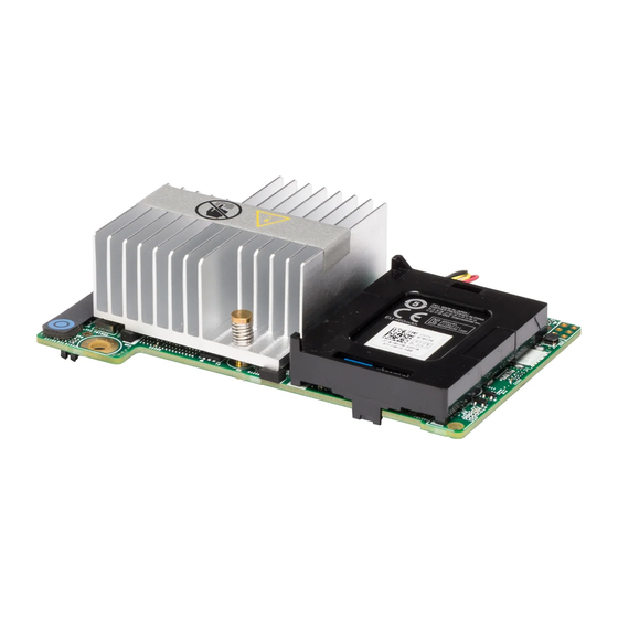
1. release lever (2) 2. PERC stack-up connector 3. PERC mini blade controller 4. screws (2) Figure 3. Removing and Installing the PERC Mini Monolithic Controller 1. release lever (2) 6. touch points (2) 2. storage-controller card holder 7. storage-controller card connector on the system board 3. -
Page 28: Support For Internal Multiple Controllers
After you remove the cable and power up the system, ensure that there are no warning messages during boot, and that all virtual disks are online and optimal. If you are using Dell OpenManage, see the Dell OpenManage documentation at dell.com/support/manuals for additional instructions. - Page 29 CAUTION: If you remove any cables other than the ones added to enable redundant path support, the enclosure and disks can get disconnected, and virtual disk may fail. Perform the following steps to configure the hardware to utilize redundant paths on the PERC H810 card: Set up an enclosure on the PERC H810 card.
-
Page 31: Driver Installation
Driver Installation The Dell PowerEdge RAID Controller (PERC) H310, H710, H710P, and H810 cards require software drivers to operate with the supported operating systems. This chapter contains the procedures for installing the drivers for the PERC H310, H710, H710P, and H810 cards. -
Page 32: Downloading Drivers From The Dell Support Website For Windows
The system prompts you to insert the media. Insert the installation media and browse to the proper location. Select the appropriate PERC H310, H710, H710P, or H810 card from the list, click Next and continue installation. Installing Windows Server 2008/2008 R2 For A New RAID Controller... -
Page 33: Updating Existing Windows Server 2008 Or Windows Server 2008 R2
Updating The Linux Driver NOTE: PERC H310/H710/H710P/H810, PERC H700/H800 cards and both the PERC 5 and PERC 6 family of controllers use the same driver and do not require separate driver installations. Use the procedures in this section to update the driver for Linux. To ensure that you have the current version of the driver, download the updated Linux driver from dell.com/support. -
Page 34: Installing Or Updating The Rpm Driver Package With Dkms Support
NOTE: For SUSE Enterprise Linux 10 SP4, immediately following the operating system installation, download the latest driver from dell.com/support, and update the driver using the procedures detailed in this section. Perform the following steps to install the RPM package with DKMS support: Uncompress the gzipped tarball driver release package. - Page 35 You see a message similar to the following one: <driver name>, <driver version>, <new kernel version>: installed. If the previous device driver is in use, you must reboot the system for the updated driver to take effect.
-
Page 37: Management Applications For Perc Cards
The BIOS Configuration Utility, also known as <Ctrl> <R>, is a storage management application embedded on the PERC H310, H710, H710P, and H810 cards that configures and maintains RAID disk groups and virtual disks. <Ctrl> <R> is independent of the operating system. -
Page 38: Exiting The Configuration Utility
NOTE: You can access multiple controllers through the BIOS Configuration Utility (<Ctrl> <R>) by pressing <F12>. NOTE: You can access PERC H700, H800, H310, H710, H710P, or H810 cards from the same BIOS if the PERC 6/ H700/H800 firmware is 6.2.0-0013 or later. -
Page 39: Setting Up Virtual Disks
Notation Meaning and Use Example Virtual Disk 1 down- Use the down-arrow key to move to the lower menu arrow items within a menu or to a lower level menu. You ↓ can also use the down-arrow key to open a menu list Virtual Disk 4 in a popup window, such as the stripe element size menu, and select a setting. - Page 40 NOTE: The default hard drive cache policy for a virtual disk composed with SAS hard drives is disabled and with SATA hard drives is enabled. The Virtual Disk parameter cannot be changed in the BIOS Configuration Utility (<Ctrl> <R>). Use Dell OpenManage Storage Management for the hard drive cache setting operation.
-
Page 41: Virtual Disk Management
Use the arrow key to highlight a physical disk and press the spacebar, <Alt> , or <Enter> to select the disk. 10. Select additional disks, if required. NOTE: (PERC H310) Only RAID Capable physical disks are eligible to be included in a Virtual Disk. To convert physical disks to RAID Capable, see the topic Converting Physical Disk To RAID Capable For PERC H310. -
Page 42: Selecting Virtual Disk Parameters
14. Select OK to accept the settings and press <Enter> to exit the window or select Cancel and press <Enter> to exit if you do not want to change any virtual disk parameters. Converting Physical Disk To RAID Capable For PERC H310 NOTE: By default, all physical drives are discovered as Non-RAID drives. -
Page 43: Converting Physical Disk To Non-Raid For Perc H310
Repeat the procedures from step 1 to step 3 to configure another virtual disk. NOTE: The PERC H310 card supports up to 16 virtual disks per controller, and the PERC H710, H710P, and H810 cards support up to 64 virtual disks per controller. The currently configured virtual disks display on the screen. -
Page 44: Importing Or Clearing Foreign Configurations Using The Vd Mgmt Menu
The Consistency Check runs and checks the redundancy data in the virtual disks. After you start the Consistency Check, press <Esc> to display the previous menu if needed. Importing Or Clearing Foreign Configurations Using The VD Mgmt Menu When a foreign configuration exists, the BIOS screen displays the message Foreign configuration(s) found on adapter. - Page 45 • The physical disks in a non-redundant virtual disk are removed. The following constraints apply to the physical disks that are considered for import: • The disk state of a physical disk can change from the time the foreign configuration is scanned to when the actual import occurs.
-
Page 46: Break Mirror
A Break Mirror operation is an operation that can be performed only on RAID1 arrays. It provides a way to 'split' the mirror and spin-down one of the hard disks, which can then be imported into the configuration of a different PERC H310, H710, H710P, or H810 controller. -
Page 47: Managing Dedicated Hot Spares
Perform the following steps to select whether to import the virtual disk or discard the preserved cache: On the VD Mgmt screen, click on a controller icon. Press <F2> to display the available actions. Select Manage Preserved Cache. A message is displayed advising you to import the foreign configuration before you discard the preserved cache to avoid losing data belonging to the foreign configuration. -
Page 48: Deleting Virtual Disks
Deleting Virtual Disks NOTE: You cannot delete a virtual disk during an initialization. NOTE: Warning messages appear stating the effect of deleting a virtual disk. Click OK twice to complete the virtual disk deletion. To delete virtual disks, perform the following steps in the BIOS Configuration Utility (<Ctrl> <R>): Press <Ctrl>... -
Page 49: Bios Configuration Utility Menu Options
BIOS Configuration Utility Menu Options The first menu that is displayed when you access the BIOS Configuration Utility <Ctrl> <R> is the main menu screen. It lists the controller, controller number, and other information, such as the slot number. On the screen, you can use the arrow keys to select the RAID controller you want to configure. - Page 50 Menu Item Selected in Left Panel Information Displayed in Right Panel • Security property of the Disk Group Virtual Disks Disk Group # Properties: • Number of virtual disks (VD) • Number of physical disks (PD) • Space available in the virtual disk •...
-
Page 51: Virtual Disk Actions
Verifies the correctness of the redundancy data in the selected virtual disk. The option is on a virtual disk available only if RAID level 1, 5, 6, 10, 50, or 60 is used. The PERC H310, H710, H710P, or H810 cards automatically correct any differences found in the data. -
Page 52: Physical Disk Management (Pd Mgmt)
Max Device Link Rate • Negotiated Link Rate • Dell Certified Disk Physical Disk Actions The following table describes the actions you can perform on physical disks. For procedures that can be used to perform the actions, see the topic Physical Disk Management (PD Mgmt). -
Page 53: Rebuild
For information on getting the best rebuild performance from your RAID controller, see the documentation at dell.com/support/manuals. The listed rates in the following table were taken during single disk failure with no I/O present on a PERC H810 card connected to a single PowerVault MD1220 enclosure. -
Page 54: Foreign Configuration View
Select the option to specify a virtual disk as the boot disk Select Bootable Device on the controller. NOTE: For PERC H310 the option may be a Virtual Disk Non-RAID drive. The option is displayed if you have built virtual disks. -
Page 55: Creating Global Hot Spares
Creating Global Hot Spares You can use a global hot spare to replace a failed physical disk in any redundant array as long as the capacity of the global hot spare is equal to or larger than the coerced capacity of the failed physical disk. Perform the following steps to create global hot spares: Press the down-arrow key to highlight a physical disk to change to a global hot spare. -
Page 56: Restrictions And Limitations
NOTE: The replacement disk must be a hot spare or an unconfigured disk without a foreign configuration. It must have the same or greater capacity and should be of the same type as the disk it is replacing. Restrictions and Limitations The following restrictions and limitations apply to the Replace Member operation: •... -
Page 57: Controller Management
Press <Tab> to move the cursor to the Select Boot Device in the Settings box. Press the down-arrow key to display a list of virtual disks and Non-RAID physical disks (PERC H310 only). Use the down-arrow key to highlight a virtual disk or Non-RAID physical disk (PERC H310 only). -
Page 58: Disabling Auto Import
NOTE: The controller automatically imports every optimal and degraded foreign configuration without enabling the feature if there is no native configuration on the controller. To enable Auto Import: Press <Ctrl> <N> to access the Ctrl Mgmt menu screen. Press <Tab> to move the cursor to Enable Auto Import in the Settings box. Press the spacebar to select Enable Auto Import. -
Page 59: Exiting The Uefi Raid Configuration Utility
Options may also be grayed out if the feature is supported in existing configuration. NOTE: Background operations are blocked on the PERC H310 controller in the UEFI RAID Configuration Utility and no operation progress updates are to be seen. -
Page 60: Virtual Disk Management
Safe mode on errors: The system will continue booting as long as the boot volume is not on this controller. Drives connected to the controller will be reported as unconfigured good drives to the RAID management utilities upon a successful boot. No configuration changes will be allowed, except to clear the controller configuration if desired. -
Page 61: Cachecade
CacheCade The Dell PowerEdge RAID Controller (PERC) H710, H710P, and H810 cards support CacheCade, a feature that can improve application performance by increasing read caching capacity. The CacheCade feature makes use of high performing solid state disks (SSDs) as a secondary tier of cache. CacheCade provides faster reads and maximizes transactional I/O performance. -
Page 62: Cachecade Virtual Disk Management
CacheCade Virtual Disk Management The Virtual Disk Management screen is the first screen that is displayed when you access a RAID controller from the main menu screen on the BIOS Configuration Utility. The following are CacheCade-related actions you can perform through the virtual disk management menu: •... -
Page 63: Deleting Cachecade Virtual Disks
Deleting CacheCade Virtual Disks To delete CacheCade virtual disks, perform the following steps in the BIOS Configuration Utility: Press <Ctrl> <N> to access the Virtual Disk Management screen. Use the arrow keys to move the cursor to the CacheCade Disk Group or Virtual Disks heading. Press <F2>. - Page 64 • Any number of SSDs can be added to a CacheCade virtual disk. • There is no SAS and SATA mixing allowed within a CacheCade virtual disk, so SATA SSDs cannot be added to a SAS CacheCade virtual disk and vice versa. •...
-
Page 65: Security Key And Raid Management
There is one security key per controller. You can manage the security key under Local Key Management (LKM). The key can be escrowed in to a file using Dell OpenManage. The security key is used by the controller to lock and unlock access to encryption-capable physical disks. -
Page 66: Creating A Security Key
Creating A Security Key Perform the following steps to create a security key on the controller: NOTE: There is no passphrase backup option when you create a security key; you need to remember your passphrase. During the host system boot up, press <Ctrl> <R> when the BIOS screen is displayed. The Virtual Disk Management screen is displayed. -
Page 67: Deleting A Security Key
NOTE: If there is an existing configuration on the controller, it is updated with the new security key. If you had previously removed any secured disks, you still need to supply the old passphrase to import them. Deleting A Security Key NOTE: Delete Key is active if there is a security key present on the controller. -
Page 68: Securing Pre-Existing Virtual Disks
NOTE: If you are importing a virtual disk originally secured with a local key (LKM), you are prompted for the passphrase used to secure that virtual disk. NOTE: A secured VD cannot be imported using the PERC H310 card. Perform the following steps when importing a foreign secured virtual disk: During the host system bootup, press <Ctrl>... -
Page 69: Instant Secure Erase
Press <F2> to display a menu of available actions. Select Import to import the foreign configuration or Clear to delete the foreign configuration. Press <Enter>. NOTE: To Clear, you need to Instant Secure Erase foreign configurations secured with a different security key. If you select to Import the configuration, the Secure Foreign Import screen is displayed. -
Page 70: Failure To Delete Security Key
there is a security key present. Select the Secure VD option as No in the Create New VD menu. See the topic Creating Virtual Disks for steps on how to create an unsecured virtual disk. Failure To Delete Security Key A security key is used to lock or unlock access to a security-enabled component. -
Page 71: Troubleshooting
Troubleshooting To get help with your Dell PowerEdge RAID Controller (PERC) H310, H710, H710P and H810, you can contact your Dell Technical Service representative or see dell.com/support. BIOS Error Messages The controller BIOS read-only memory (ROM) provides Int 13h functionality (disk I/O) for the virtual disks connected to the controller. -
Page 72: Missing Disks In Virtual Disk Error Message
Corrective To resolve this issue, allow the battery to charge fully. If the problem persists, the battery or Action: controller memory may be faulty; contact Dell Technical Support. Missing Disks In Virtual Disk Error Message Error Message: The following virtual disks have missing disks: (x). If you proceed (or load the configuration utility), these virtual disks will be marked OFFLINE and will be inaccessible. -
Page 73: Dirty Cache Data Error Message
Corrective Check the cable connections and fix any issues. Restart the system. If there are no cable Action: problems, press any key or <C> to continue. Dirty Cache Data Error Message Error Message: The following virtual disks are missing: (x). If you proceed (or load the configuration utility), these virtual disks will be removed from your configuration. -
Page 74: Adapter At Baseport Not Responding Error Message
Error Message: Adapter at Baseport xxxx is not responding, where xxxx is the baseport of the controller. Corrective Contact Dell Technical Support. Action: Offline Or Missing Virtual Drives With Preserved Cache Error Message Error Message: There are offline or missing virtual drives with preserved cache. -
Page 75: Virtual Disks Partially Degraded Error Message
Corrective Allow the battery to charge fully to resolve this problem. If the problem persists, the battery or Action: controller memory may be faulty. Contact Dell Technical Support. Firmware Fault State Error Message Error Message: Firmware is in Fault State. -
Page 76: Foreign Configuration Not Found In
Corrective Action: Ensure all your PDs are present and all VDs are in optimal state. Clear the Action: foreign configuration using <Ctrl> <R> or Dell OpenManage Server Administrator Storage Management. CAUTION: The physical disk goes to Ready state when you clear the foreign configuration.Error Message -
Page 77: Configured Disks Removed Or Not Accessible Error Message
This message may appear for controller without battery, depending on the virtual disks’ policies. Corrective • The controller battery is missing or currently inaccessible, contact Dell support if the Action: problem persist after 30 minutes. • The controller battery is completely discharged and needs to be charged for it to become active. -
Page 78: Memory Errors
The controller logs an event to the controller’s internal event log and a message during POST is displayed indicating a multi-bit error has occurred. NOTE: In case of a multi-bit error, contact Dell Technical Support. Preserved Cache State The controller preserves the dirty cache from a virtual disk if the virtual disk becomes offline or is deleted because of missing physical disks. -
Page 79: Physical Disk Issues
Physical Disk In Failed State Issue: One of the physical disks in the disk array is in the failed state. Corrective Update the PERC cards to the latest firmware available on dell.com/support. Action: Unable to Rebuild A Fault Tolerant Virtual Disk Issue: Cannot rebuild a fault tolerant virtual disk. -
Page 80: Multiple Disks Become Inaccessible
Optimal state without a rebuild occurring. NOTE: You can use the BIOS Configuration Utility (<Ctrl> <R>) or Dell OpenManage storage management application to perform a manual rebuild of multiple physical disks. For information on rebuilding a single physical... -
Page 81: Physical Disk Fails During Reconstruction On Redundant Virtual Disk
NOTE: For information about where to find reports of SMART errors that could indicate hardware failure, see the Dell OpenManage storage management documentation at dell.com/support/manuals. Smart Error Detected On A Physical Disk In A Redundant Virtual Disk Issue: A SMART error is detected on a physical disk in a redundant virtual disk. -
Page 82: Smart Error Detected On A Physical Disk In A Non-Redundant Virtual Disk
Smart Error Detected On A Physical Disk In A Non-Redundant Virtual Disk Issue: A SMART error is detected on a physical disk in a redundant virtual disk. Corrective Perform the following steps: Action: 1. Back up your data. 2. Use Replace Member or set up a global hot spare to replace the disk automatically. NOTE: For more information about the Replace Member feature, see the topic Using Replace Member And Revertible Hot... -
Page 83: Driver Does Not Auto-Build Into New Kernel
Corrective The error message is displayed when the Linux Small Computer System Interface (SCSI) mid- Action: layer asks for physical disk cache settings. The controller firmware manages the virtual disk cache settings on a per controller and a per virtual disk basis, so the firmware does not respond to this command. -
Page 84: Disk Carrier Led Indicators
Disk Carrier LED Indicators The LED on the physical disk carrier indicates the state of each physical disk. Each disk carrier in your enclosure has two LEDs: an activity LED (green) and a status LED (bicolor, green/amber). The activity LED is active whenever a disk is being accessed while the status LED indicates when a disk is being spun up, is rebuilding, or is in a fault state. -
Page 85: Appendix: Raid Description
Summary Of RAID Levels NOTE: PERC H710, H710P and H810 cards support all RAID levels listed below. PERC H310 supports RAID 5 with limited performance and does not support RAID 6 and RAID 60. -
Page 86: Disk Mirroring
For example, in a four-disk system using only disk striping (used in RAID 0), segment 1 is written to disk 1, segment 2 is written to disk 2, and so on. Disk striping enhances performance because multiple physical disks are accessed simultaneously, but disk striping does not provide data redundancy. - Page 87 RAID 6 combines dual distributed parity with disk striping. This level of parity allows for two disk failures without duplicating the contents of entire physical disks. Figure 8. Example of Distributed Parity (RAID 5) NOTE: Parity is distributed across multiple physical disks in the disk group. Figure 9.