
Related Manuals for UNI-T UT60A


Summary of Contents for UNI-T UT60A
-
Page 1: Table Of Contents
Model UT60A: OPERATING MANUAL Table of Contents Title Page Overview Unpacking Inspection Safety Information Rules For Safe Operation International Electrical Symbols The Meter Structure Rotary Switch Functional Buttons Display Symbols Measurement Ranges Selecting a Measurement Range Manual Ranging and Autoranging Measurement Operation AC &... - Page 2 Model UT60A: OPERATING MANUAL Title Page Maintenance General Service Testing the Fuses Replacing the Battery Replacing the Fuses RS232C Serial Port RS232C Port Cable Setting of RS232C Serial Ports System Requirements for Installing the UT60A Interface Program...
-
Page 3: Overview
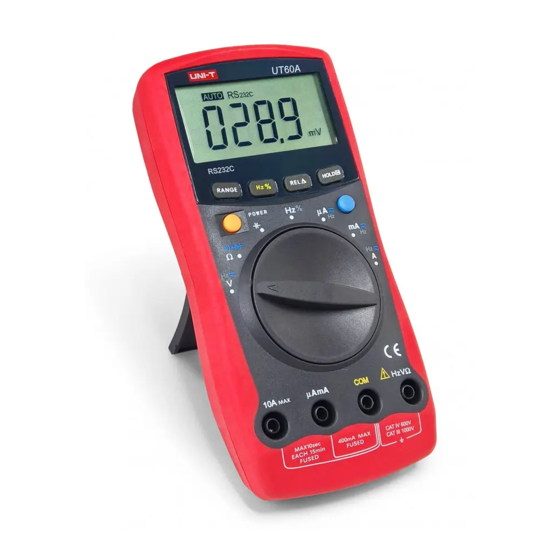
To avoid electric shock or personal injury, read the "Safety Information" and "Rules for Safe Operation" carefully before using the Meter. Digital Multimeter Model UT60A (hereafter referred to as "the Meter") has autorange and manual range options with maximum reading 3999. The enclosure structure design adopted advanced "co-injection"... -
Page 4: Unpacking Inspection
Model UT60A: OPERATING MANUAL Unpacking Inspection Open the package case and take out the Meter. Check the following items carefully to see any missing or damaged part: Item Description Operating Manual 1 piece Test Lead 1 pair 9V Battery (NEDA1604, 6F22 or 006P) -
Page 5: Safety Information
Model UT60A: OPERATING MANUAL Safety Information This Meter complies with the standards IEC61010: in pollution degree 2, overvoltage category (CAT. III 1000V, CAT. IV 600V) and double insulation. CAT. III: Distribution level, fixed installation, with smaller transient overvoltages than CAT. IV CAT IV:Primary supply level, overhead lines, cable systems etc. -
Page 6: Rules For Safe Operation
Model UT60A: OPERATING MANUAL Rules For Safe Operation (1) Warning To avoid possible electric shock or personal injury, and to avoid possible damage to the Meter or to the equipment under test, adhere to the following rules: Before using the Meter inspect the case. Do not use the Meter if it is damaged or the case (or part of the case) is removed. - Page 7 Model UT60A: OPERATING MANUAL Rules For Safe Operation (2) Before measuring current, check the Meter's fuses and turn off power to the circuit before connecting the Meter to the circuit. Replace the battery as soon as the battery indicator appears. With a low battery, the Meter might produce false readings that can lead to electric shock and personal injury.
-
Page 8: International Electrical Symbols
Model UT60A: OPERATING MANUAL International Electrical Symbols AC (Alternating Current). DC (Direct Current). AC or DC. Grounding. Double Insulated. Deficiency of Built-In Battery. Continuity Test. Diode. Capacitance Test. Fuse. Warning. Refer to the Operating Manual. Conforms to Standards of European Union. -
Page 9: The Meter Structure
Model UT60A: OPERATING MANUAL The Meter Structure... - Page 10 Model UT60A: OPERATING MANUAL...
- Page 11 Model UT60A: OPERATING MANUAL...
- Page 12 Model UT60A: OPERATING MANUAL...
- Page 13 Model UT60A: OPERATING MANUAL...
-
Page 14: Display Symbols
Model UT60A: OPERATING MANUAL Display Symbols (1) nFHz... - Page 15 Model UT60A: OPERATING MANUAL Display Symbols (2)
- Page 16 Model UT60A: OPERATING MANUAL...
-
Page 17: Measurement Ranges
Model UT60A: OPERATING MANUAL Measurement Ranges (1) A measurement range determines the highest value the Meter can measure. Most Meter functions have more than one range. See "Accuracy Specifications." A. Selecting a Measurement Range Being in the right measurement range is important: If the range is too low for the input, the Meter displays to indicate an overload. - Page 18 Model UT60A: OPERATING MANUAL Measurement Ranges (2) To enter and exit the manual range mode: Press RANGE. The Meter enters the manual range mode and turns off. Each presses of RANGE increments the range. When the highest range is reached, the Meter wraps to the lowest range.
-
Page 19: Measurement Operation
Model UT60A: OPERATING MANUAL Measurement Operation (1) A. AC & DC Voltage Measurement Warning To avoid harms to you or damages to the Meter from electric shock, please do not attempt to measure voltages higher than 1000V / 750V rms although readings may be obtained. - Page 20 Model UT60A: OPERATING MANUAL Measurement Operation (2) Note In each range, the Meter has an input impedance of 10M . This loading effect can cause measurement errors in high impedance circuits. If the circuit impedance is less than or equal to 10k , the error is negligible (0.1% or less).
-
Page 21: Measuring Continuity, Diodes
Model UT60A: OPERATING MANUAL Measurement Operation (3) Note In each range, the Meter has an input impedance of 10M . This loading effect can cause measurement errors in high impedance circuits. If the circuit impedance is less than or equal to 10k , the error is negligible (0.1% or less). - Page 22 Model UT60A: OPERATING MANUAL Measurement Operation (4) Note The LCD displays indicating the circuit being tested is open. When continuity testing has been completed, disconnect the connection between the testing leads and the circuit under test. Testing Diodes (see figure 6)
- Page 23 Model UT60A: OPERATING MANUAL Measurement Operation (5) Note In a circuit, a good diode should still produce a forward voltage drop reading of 0.5V to 0.8V; however, the reverse voltage drop reading can vary depending on the resistance of other pathways between the probe tips.
-
Page 24: Capacitance Measurement
Model UT60A: OPERATING MANUAL Measurement Operation (6) Connect the test leads across with the object being measured. The measured value shows on the display. Note The test leads can add 0.1 to 0.2 of error to resistance measurement. To obtain precision readings in low-resistance measurement, that is the range of 400.0 , short-circuit the input terminals... - Page 25 Model UT60A: OPERATING MANUAL Measurement Operation (7) Warning To avoid damage to the Meter or to the equipment under test, disconnect circuit power and discharge all high-voltage capacitors before measuring capacitance. Use the DC Voltage function to confirm that the capacitor is discharged.
-
Page 26: Frequency & Duty Cycle Measurement
Model UT60A: OPERATING MANUAL Measurement Operation (8) D. Frequency & Duty Cycle Measurement (see figure 9) Select Hz Test Black (figure 9) Frequency Measurement The measurement ranges are from 10Hz to 40MHz. To measure frequency, connect the Meter as follows: Insert the red test lead into the HzV terminal and the black test lead into the COM terminal. - Page 27 Model UT60A: OPERATING MANUAL Measurement Operation (9) Range Signal Frequency Requirement Range 200mV 200 A 10Hz~1kHz 20mA When Hz measurement has been completed, disconnect the connection between the testing leads and the circuit under test. Duty Cycle Measurement The duty cycle measurement range is 0.1% ~ 99.9%.
-
Page 28: Dc Or Ac Current Measurement
Model UT60A: OPERATING MANUAL Measurement Operation (10) E. DC or AC Current Measurement (see figure 10) Select Black Hz or (figure 10) Warning Never attempt an in-circuit current measurement where the open-circuit voltage between the circuit and ground is greater than 250V. - Page 29 Model UT60A: OPERATING MANUAL Measurement Operation (11) The Meter defaults to DC current measurement mode. To toggle between DC and AC current measurement function, press BLUE button. AC current is displayed as an mean value (calibrated against sine wave effective value).
-
Page 30: The Power Button
Model UT60A: OPERATING MANUAL The POWER button This is a self-lock switch use to turn on or off the power of the Meter. The BLUE button It uses for selecting the required measurement function when there is more than one function at one position of the rotary switch. -
Page 31: Operation Of Hold Mode
Model UT60A: OPERATING MANUAL Operation of Hold Mode Warning To avoid possibility of electric shock, do not use Hold mode to determine if circuits are without power. The Hold mode will not capture unstable or noisy readings. The Hold mode is applicable to all measurement functions. -
Page 32: General Specifications
Model UT60A: OPERATING MANUAL General Specifications Maximum Voltage between any Terminals : 1000V rms. and Grounding Fused Protection :0.5A, 250V fast type Glass fuse, 5x20 mm. AmA Input Terminal Fused Protection :10A, 250V fast type Glass for 10A Input Terminal fuse, 5x20 mm. -
Page 33: Accuracy Specifications
Model UT60A: OPERATING MANUAL Accuracy Specifications (1) Accuracy: (a% reading + b digits) guarantee for 1 year. Operating temperature: 23 Relative humidity: <75%. Temperature coefficient: 0.1 x (specified accuracy) / 1 A. AC Voltage Overload Range Resolution Accuracy Protection 10mV... -
Page 34: Continuity, Diodes & Resistance Test
Model UT60A: OPERATING MANUAL Accuracy Specifications (2) C. Continuity, Diodes & Resistance Test Range Resolution Accuracy Overload Protection Continuity Test Approximate (400.0 ) Diode (1.2%+2) 600Vp (1%+2) 400k (1.2%+2) (1.5%+2) Remarks: Continuity Test (400.0 ) Range: Buzzer beeps continuously. Open circuit voltage approximate 0.45V. -
Page 35: Capacitance
Model UT60A: OPERATING MANUAL Accuracy Specifications (3) D. Capacitance Overload Range Resolution Accuracy Protection 40nF 10pF 400nF 100pF (3%+5) 600Vp 40 F 10nF 100 F 100nF (4%+5) E. Frequency & Duty Cycle Overload Range Resolution Accuracy Protection 10Hz~ (0.1%+3) 10MHz 0.1%~... -
Page 36: Dc Current
Model UT60A: OPERATING MANUAL Accuracy Specifications (4) DC Current Overload Range Resolution Accuracy Protection 400 A 0.1 A (1%+2) 0.5A, 250V, 4000 A fast type Glass 40mA 0.01mA fuse, 5x20mm (1.2%+3) 400m A 0.1mA 0.001A 10A, 250V, (1.5%+5) fast type Glass 0.01A... -
Page 37: Maintenance
Model UT60A: OPERATING MANUAL Maintenance (1) This section provides basic maintenance information including battery and fuse replacement instruction. Warning Do not attempt to repair or service your Meter unless you are qualified to do so and have the relevant calibration, performance test, and service information. -
Page 38: Replacing The Battery
Model UT60A: OPERATING MANUAL Maintenance (2) To test the fuse: Set the rotary switch to and select pressing BLUE button. Plug a test lead into the terminal HzV and touch the probe tip to the 10A or AmA terminal. If the Meter beeps, the fuse is good. -
Page 39: Replacing The Fuses
Model UT60A: OPERATING MANUAL Maintenance (3) Remove the screw from the battery compartment, and separate the battery compartment from the case bottom. Remove the battery from the battery compartment. Replace the battery with a new 9V battery (NEDA1604, 6F22 or 006P). - Page 40 Model UT60A: OPERATING MANUAL Maintenance (4) Install ONLY replacement fuses with the identical type and specification as follows and make sure the fuse is fixed firmly in the bracket. Fuse 1:0.5A, 250V, fast type Glass fuse, 5x20mm. Fuse 2: 10A, 250V, fast type Glass fuse, 5x20 mm.
-
Page 41: Rs232C Serial Port
Model UT60A: OPERATING MANUAL RS232C Serial Port (1) A. RS232C Port Cable Computer Meter D-sub D-sub D-sub 9 Pin 25 Pin Remark 9 Pin Name Female Female Male Receiving Data Transmitting Data Data Terminal Ready Grounding Data Set Ready Request To... -
Page 42: System Requirements For Installing The Ut60A Interface Program
RS232C Serial Port (2) C. System Requirements for Installing the UT60A Interface Program To use UT60A Interface Program, you need the following hardware and software: An IBM PC or equivalent computer with 80486 or higher processor and 640 x 480 pixel or better monitor. - Page 43 Model UT60A: OPERATING MANUAL...
- Page 44 Model UT60A: OPERATING MANUAL Copyright 2001 Uni-Trend International Limited. All rights reserved. Manufacturer: UNI-TREND TECHNOLOGY(DONG GUAN)LIMITED Address: Dong Fang Da Dao, Bei Shan Dong Fang Industrial Development District, Hu Men Town, Dong Guan City, Guang Dong Province, China Headquarters: Uni-Trend International Limited...