
Related Manuals for UNI-T UT60B


Summary of Contents for UNI-T UT60B
-
Page 1: Table Of Contents
Model UT60B/C/E: OPERATING MANUAL Table of Contents Title Page Overview Unpacking Inspection Safety Information Rules For Safe Operation International Electrical Symbols The Meter Structure Rotary Switch Functional Buttons Display Symbols Measurement Ranges Selecting a Measurement Range Manual Ranging and Autoranging... - Page 2 Model UT60B/C/E: OPERATING MANUAL Page Diode Test Capacitance Frequency & Duty Cycle Temperature (Model UT60C/UT60E) DC Current AC Current Maintenance General Service Testing the Fuses Replacing the Battery Replacing the Fuses RS232C Serial Port (Model UT60E) RS232C Port Cable Setting of RS232C Serial Ports...
-
Page 3: Overview
Model UT60E also has true rms reading for AC voltage and AC current measurements. Except where noted, the descriptions and instructions in this Operating Manual apply to all Model UT60B/UT60C /UT60E Unless otherwise identified, all figures show the Model UT60B. -
Page 4: Unpacking Inspection
Model UT60B/C/E: OPERATING MANUAL Unpacking Inspection Open the package case and take out the Meter. Check the following items carefully to see any missing or damaged part: Item Description Operating Manual 1 piece Test Lead 1 pair Test Clip 1 pair... -
Page 5: Rules For Safe Operation
Model UT60B/C/E: OPERATING MANUAL Rules For Safe Operation Warning To avoid possible electric shock or personal injury, and to avoid possible damage to the Meter or to the equipment under test, adhere to the following rules: l Before using the Meter inspect the case. Do not use the Meter if it is damaged or the case (or part of the case) is removed. -
Page 6: International Electrical Symbols
Model UT60B/C/E: OPERATING MANUAL cable and test clip from the Meter and turn the Meter power off before opening the Meter case. l When servicing the Meter, use only the same model number or identical electrical specifications replacement parts. l The internal circuit of the Meter shall not be altered at will to avoid damage of the Meter and any accident. -
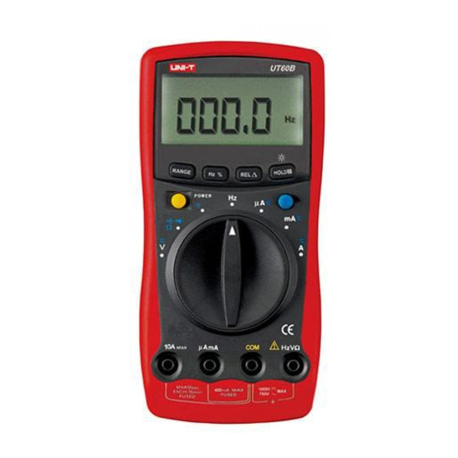
Page 7: The Meter Structure
Model UT60B/C/E: OPERATING MANUAL The Meter Structure (see figure 1) (figure 1) 1 LCD Display 2 Functional Buttons 3 Rotary Switch 4 HzV Input Terminal: Input for voltage, frequency/duty cycle, resistance, diode, continuity and capacitance measurements. 5 COM Input Terminal: Return terminal for all measurements. -
Page 8: Rotary Switch
Model UT60B/C/E: OPERATING MANUAL Rotary Switch Below table indicated for information about the rotary switch positions. Rotary Switch Function Position DC voltage measurement range from 400.0mV to 1000V or AC voltage measurement range from 4.000V to 750.0V. Continuity test. Diode test. -
Page 9: Functional Buttons
Model UT60B/C/E: OPERATING MANUAL Functional Buttons (1) Below table indicated for information about the functional button operations. Button Measuring Operation Performed Function POWER Any rotary Turn the power on and off. switch position Switches between AC and DC voltage; the Meter beeps. DC is default. - Page 10 Model UT60B/C/E: OPERATING MANUAL Functional Buttons (2) l Press RANGE to enter the Any rotary switch manual ranging mode; the Meter position beeps. exceptHz Manually selecting a range causes the Meter to exit the Hold and REL modes. RANGE l Press RANGE to step through the ranges available for the selected function;...
-
Page 11: Display Symbols
12 ~ 16 (figure 2) Number Symbol Meaning Indicator for AC voltage or current. Model UT60B/UT60C: The displayed value is the mean value. Model UT60E : The displayed value is the true rms value. TRMS The Model UT60E: Indicator for true rms value. -
Page 12: Measurement Ranges
Model UT60B/C/E: OPERATING MANUAL Display Symbols (1) (see figure 2) , k , Ohm. The unit of resistance. kilohm. 1 x 10 or 1000 ohms. Megaohm. 1 x 10 or 1,000,000 ohms. Farad. The unit of capacitance. Microfarad. 1 x 10 or 0.000001 farads. - Page 13 Model UT60B/C/E: OPERATING MANUAL Measurement Ranges (2) l In the autorange mode, the Meter selects the best range for input signals. This allows you to switch test points without having to reset the range. l In the manual range mode, you may select the range.
-
Page 14: Measurement Operation A. Dc Voltage Measurement
Model UT60B/C/E: OPERATING MANUAL Measurement Operation (1) A.DC Voltage Measurement (see figure 3) (figure 3) Warning To avoid harms to you or damages to the Meter from electric shock, please do not attempt to measure voltages higher than 1000VDC / 750VAC rms although readings may be obtained. -
Page 15: Ac Voltage Measurement
Model UT60B/C/E: OPERATING MANUAL Measurement Operation (2) B. AC Voltage Measurement (see figure 4) (figure 4) Warning To avoid harms to you or damages to the Meter from electric shock, please do not attempt to measure voltages higher than 1000VDC / 750VAC rms although readings may be obtained. -
Page 16: Measuring Resistance
Model UT60B/C/E: OPERATING MANUAL Measurement Operation (3) C.Measuring Resistance (see figure 5) (figure 5) Warning To avoid damages to the Meter or to the devices under test, disconnect circuit power and discharge all the high-voltage capacitors before measuring resistance. The resistance ranges are: 400.0 , 4.000k , 40.00k 400.0k , 4.000M and 40.00M . -
Page 17: Testing For Continuity
COM terminal. 2. Model UT60C/UT60E: Set the rotary switch to and press BLUE button to select measurement mode. Model UT60B: Set the rotary switch to and press BLUE button to select measurement mode. 3. The buzzer sounds if the resistance of a circuit under test is... -
Page 18: Testing Diodes
COM terminal. 2. Model UT60C/UT60E: Set the rotary switch to and press BLUE button to select measurement mode. Model UT60B:Set the rotary switch to and press BLUE button to select measurement mode. 3. For forward voltage drop readings on any semiconductor component, place the red test lead on the component’s anode... -
Page 19: Capacitance Measurement
2. Model UT60C/UT60E: Set the rotary switch to and pressBLUE button to select nF measurement mode. Model UT60B: Set the rotary switch to 3. Connect the test leads across with the object being measured. The measured value shows on the display. -
Page 20: Frequency Measurement
Model UT60B/C/E: OPERATING MANUAL Measurement Operation (7) anode & black clip to cathode instead of using test leads as mentioned above. l To minimize the effect of capacitance stored in the test leads, the test lead should be as short as possible. To measure a small value of capacitance, use REL mode to remove the leads capacitance. -
Page 21: Measuring Duty Cycle
Model UT60B/C/E: OPERATING MANUAL Measurement Operation (8) l To obtain a stable reading when measuring input scope 30V rms frequency signal: Set the rotary switch to V Then press Hz% to select Hz measurement mode to obtain frequency value. When input scope 30V rms, please follow the above step 2. -
Page 22: Temperature Measurement (Model Ut60C/Ut60E)
Model UT60B/C/E: OPERATING MANUAL Measurement Operation (9) I. Model UT60C/UT60E: Temperature Measurement (see figure 10) (figure 10) The temperature measurement range is measure temperature, connect the Meter as follows: 1. Insert the red temperature probe into the and the black temperature probe into the COM terminal. - Page 23 10A terminal and the black test lead into the COM terminal. Model UT60B:Insert the red test lead into the 10A terminal and the black test lead into the COM terminal. Use the10A terminal and A range if the current value to be tested is an unknown.
-
Page 24: Operation Of Hold Mode
Model UT60B/C/E: OPERATING MANUAL Operation of Hold Mode Warning To avoid possibility of electric shock, do not use Hold mode to determine if circuits are without power. The Hold mode will not capture unstable or noisy readings. The Hold mode is applicable to all measurement functions. -
Page 25: The Power Button
Press and hold HOLD H again for over 2 seconds to turn the Display Backlight off, otherwise it will stay on continuously. Sleep Mode (Model UT60B/UT60C) To preserve battery life, the Meter automatically turns off if you do not turn the rotary switch or press any button for around 30 minutes. -
Page 26: General Specifications
Maximum Voltage between any Terminals and Grounding: 1000V. Fused Protection for Input Terminal: Model UT60B: Glass fuse, 0.5A, 250V, fast type, 5x20mm. Fused Protection for Input Terminal: Model UT60C/E: Glass fuse, 0.5A, 250V, fast type, 5x20mm. Fused Protection for 10AInput Terminal: UT60B/C/E: Glass fuse, 10A, 250V, fast type, 5x20mm. -
Page 27: Accuracy Specifications
750V AC rms 100mV 400V continuous. 750V (1.2%+5) Remarks: l Input impedance 10M l Model UT60B/UT60C: displays effective value of sine wave (mean value response). Model UT60E: displays true rms value. l Frequency response 40Hz~400Hz. C. Resistance Overload Range Resolution... -
Page 28: Continuity Test
Model UT60B/C/E: OPERATING MANUAL Accuracy Specifications (2) D Continuity Test Overload Range Resolution Accuracy Protection 1000Vp 400.0 Approximate 100 Remarks: l Buzzer beeps continuously. l Open circuit voltage approximate 0.45V. E. Diode Test Range Resolution Overload Protection Diode 1000Vp Remarks: l Open circuit voltage approximate 1.48V. -
Page 29: Temperature (Model Ut60C/Ut60E)
Model UT60B/C/E: OPERATING MANUAL Accuracy Specifications (3) H.Temperature (Model UT60C/UT60E) Overload Protection: Glass fuse 0.5A, 250V, fast type, 5x20mm. I. DC Current 400 A 0.1 A 0.5A, 250V, fast type Glass fuse, 5x20 mm. 10A, 250V, fast type Glass fuse, 5x20 mm. -
Page 30: Ac Current
Glass fuse, 5x20 mm. 10A, 250V, fast type Glass fuse, 5x20 mm. Remarks: Model UT60B/UT60C : displays effective value of sine wave (mean value response). Model UT60E : displays true rms value. l 4A & 10A Range: For continuous measurement 10 seconds and interval not less than 15 minutes. -
Page 31: Maintenance
To test the fuse: 1. Model UT60C/UT60E: Set the rotary switch to and pressBLUE button to select Model UT60B: Set the rotary switch to and press BLUE button to select 2. Plug a test lead into the terminalHzV and touch the probe... -
Page 32: Replacing The Battery
l If the Meter beeps, the fuse is good. l If the display shows , replace the fuse and test again. l If the display shows any other value, have the Meter serviced and contact your dealer immediately. If the Meter does not work while the fuse is all right, send it to your dealer for repair. -
Page 33: Replacing The Fuses
Model UT60B/C/E: OPERATING MANUAL D. Replacing the Fuses (see figure 13) (figure 13) Warning To avoid electrical shock or arc blast, or personal injury or damage to the Meter, use specified fuses ONLY in accordance with the following procedure. To replace the Meter’s fuse: Press the POWER to turn the Meter off and remove all connections from the terminals. - Page 34 Model UT60B/C/E: OPERATING MANUAL Rejoin the battery compartment and the case top, and reinstall the screw. 7. Rejoin the case bottom and case top, and reinstall the 2 screws and 2 rubber feet. Replacement of the fuses is seldom required. Burning of a fuse...
-
Page 35: Rs232C Serial Port (Model Ut60E)
Model UT60B/C/E: OPERATING MANUAL RS232C Serial Port (Model UT60E) A.RS232C Port Cable The Meter Computer D-sub D-sub D-sub Pin Name 9 Pin Female 25 Pin Female B.Setting of RS232C Serial Ports Default of RS232C serial port for communication is set as:... - Page 36 Model UT60B/C/E: OPERATING MANUAL...
- Page 37 Model UT60B/C/E: OPERATING MANUAL...
- Page 38 Model UT60B/C/E: OPERATING MANUAL Copyright 2001 Uni-Trend International Limited. All rights reserved. Manufacturer: UNI-TREND TECHNOLOGY(DONG GUAN)LIMITED Address: Dong Fang Da Dao, Bei Shan Dong Fang Industrial Development District, Hu Men Town, Dong Guan City, Guang Dong Province, China Headquarters: Uni-Trend International Limited...