
Related Manuals for UNI-T UT60D


Summary of Contents for UNI-T UT60D
-
Page 1: Table Of Contents
Model UT60D: OPERATING MANUAL Table of Contents Title Page Overview Unpacking Inspection Safety Information Rules For Safe Operation International Electrical Symbols The Meter Structure Rotary Switch Functional Buttons Display Symbols Measurement Ranges Selecting a Measurement Range Manual Ranging and Autoranging Measurement Operation AC &... - Page 2 Model UT60D: OPERATING MANUAL Page Accuracy Specifications AC Voltage DC Voltage C. Continuity, Diodes & Resistance Test D. Frequency Revolution (RPM) DC Current G. AC Current Maintenance General Service Testing the Fuses C. Replacing the Battery D. Replacing the Fuses...
-
Page 3: Overview
To avoid electric shock or personal injury, read the "Safety Information" and "Rules for Safe Operation" carefully before using the Meter. Digital Multimeter Model UT60D (hereafter referred to as "the Meter") has autorange and manual range options with maximum reading 3400. The enclosure structure design adopted advanced "co-injection"... -
Page 4: Unpacking Inspection
Model UT60D: OPERATING MANUAL Unpacking Inspection Open the package case and take out the Meter. Check the following items carefully to see any missing or damaged part: Item Description Operating Manual 1 piece Test Lead 1 pair 9V Battery (NEDA1604, 6F22 or... -
Page 5: Safety Information
Model UT60D: OPERATING MANUAL Safety Information This Meter complies with the standards IEC61010: in pollution degree 2, overvoltage category (CAT. III 1000V, CAT. IV 600V) and double insulation. CAT. III: Distribution level, fixed installation, with smaller transient overvoltages than CAT. IV CAT IV: Primary supply level, overhead lines, cable systems etc. -
Page 6: Rules For Safe Operation
Model UT60D: OPERATING MANUAL Rules For Safe Operation (1) Warning To avoid possible electric shock or personal injury, and to avoid possible damage to the Meter or to the equipment under test, adhere to the following rules: Before using the Meter inspect the case. Do not use the Meter if it is damaged or the case (or part of the case) is removed. - Page 7 Model UT60D: OPERATING MANUAL Rules For Safe Operation (2) Disconnect circuit power and discharge all high- voltage capacitors before testing continuity, diodes, resistance or current. Before measuring current, check the Meter’s fuses and turn off power to the circuit before connecting the Meter to the circuit.
-
Page 8: International Electrical Symbols
Model UT60D: OPERATING MANUAL International Electrical Symbols AC (Alternating Current) DC (Direct Current) AC or DC Grounding Double Insulated Deficiency of Built-In Battery. Continuity Test. Diode. Fuse. Warning. Refer to the Operating Manual. Conforms to Standards of European Union. -
Page 9: The Meter Structure
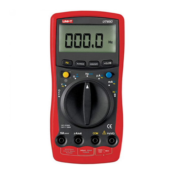
Model UT60D: OPERATING MANUAL The Meter Structure (see figure 1) (figure 1) LCD Display Functional Buttons Rotary Switch Input Terminal: Input for voltage, frequency/rpm, resistance, diode and continuity measurements. COM Input Terminal: Return terminal for all measurements. AmA Input Terminal: Input for 0.1 A to 340.0mA current measurements. -
Page 10: Rotary Switch
Model UT60D: OPERATING MANUAL Rotary Switch Below table indicated for information about the rotary switch positions. Rotary Switch Function Position Power is turned off DC voltage measurement range from 340.0mV to 1000V or AC voltage measurement range from 3.400V to 750.0V. -
Page 11: Functional Buttons
Model UT60D: OPERATING MANUAL Functional Buttons (1) Below table indicated for information about the functional button operations. Measuring Button Operation Performed Function Display Press once to turn the Display Backlight Backlight on and it shall shut off automatically in 10 seconds later. - Page 12 Model UT60D: OPERATING MANUAL Functional Buttons (2) At OFF Press Hz button while turning on position the Meter to disable Sleep Mode feature. RANGE Any rotary 1. Press RANGE to enter the switch manual ranging mode; the Meter position beeps.
-
Page 13: Display Symbols
Model UT60D: OPERATING MANUAL Display Symbols (1) (see figure 2) 9 , 10 11 , 12 OLOL (figure 2) Number Symbol Meaning Indicator for AC voltage or current. The displayed value is the mean value. Indicator for DC voltage or current. - Page 14 Model UT60D: OPERATING MANUAL Display Symbols (2) (see figure 2) , k , : Ohm. The unit of resistance. : kilohm. 1 x 10 or 1000 ohms. : Megaohm. 1 x 10 1,000,000 ohms. Hz, kHz, Hz : Hertz. The unit of frequency in cycles/second.
-
Page 15: Measurement Ranges
Model UT60D: OPERATING MANUAL Measurement Ranges (1) A measurement range determines the highest value the Meter can measure. Most Meter functions have more than one range. See "Accuracy Specifications." A. Selecting a Measurement Range Being in the right measurement range is important: If the range is too low for the input, the Meter displays to indicate an overload. - Page 16 Model UT60D: OPERATING MANUAL Measurement Ranges (2) To exit the manual range mode, press and hold RANGE for over one second. The Meter returns to the autorange mode and is displayed. Note If you manually change the measurement range after entering Hold mode, the Meter exits this mode.
-
Page 17: Measurement Operation
Model UT60D: OPERATING MANUAL Measurement Operation (1) A. AC & DC Voltage Measurement Warning To avoid harms to you or damages to the Meter from electric shock, please do not attempt to measure voltages higher thanDC1000V / AC750V rms, although readings may be obtained. - Page 18 Model UT60D: OPERATING MANUAL Measurement Operation (2) When AC voltage measurement has been completed, disconnect the connection between the testing leads and the circuit under test. DC Voltage Measurement (see figure 4) black (figure 4) The DC Voltage ranges are: 340.0mV, 3.400V, 34.00V, 340.0V and 1000V.
-
Page 19: Measuring Continuity, Diodes & Resistance
Model UT60D: OPERATING MANUAL Measurement Operation (3) B. Measuring Continuity, Diodes & Resistance Warning To avoid damages to the Meter or to the devices under test, disconnect circuit power and discharge all the high-voltage capacitors before measuring continuity, diodes & resistance. - Page 20 Model UT60D: OPERATING MANUAL Measurement Operation (4) Testing Diodes (see figure 6) black (figure 6) Use the diode test to check diodes, transistors, and other semiconductor devices. The diode test sends a current through the semiconductor junction, then measures the voltage drop across the junction.
- Page 21 Model UT60D: OPERATING MANUAL Measurement Operation (5) Connect the test leads to the proper terminals as said above to avoid error display. The LCD will display indicating open-circuit for wrong connection. The unit of diode is Volt (V), displaying the positive- connection voltage-drop value.
-
Page 22: Frequency & Revolution (Rpm) Measurement
Model UT60D: OPERATING MANUAL Measurement Operation (6) Note The test leads can add 0.1 to 0.2 of error to resistance measurement. To obtain precision readings in low-resistance measurement, that is the range of 340.0 , short-circuit the input terminals beforehand and record the reading obtained (called this reading as X). - Page 23 Model UT60D: OPERATING MANUAL Measurement Operation (7) The frequency measurement ranges are :3.4kHz, 34kHz, 340kHz, 3.4MHz, 34MHz. To measure frequency, connect the Meter as follows: Insert the red test lead into the HzV terminal and the black test lead into the COM terminal.
-
Page 24: Dc Or Ac Current Measurement
Model UT60D: OPERATING MANUAL Measurement Operation (8) D. DC or AC Current Measurement (see figure 9) black (figure 9) Warning Never attempt an in-circuit current measurement where the open-circuit voltage between the circuit and ground is greater than 250V. If the fuse burns out during measurement, the Meter may be damaged or the operator himself may be hurt. - Page 25 Model UT60D: OPERATING MANUAL Measurement Operation (9) Set the rotary switch to A Hz, mA Hz or Hz Use the 10A terminal and Hz A measurement position if the current value to be tested is an unknown. The Meter defaults to DC current measurement mode.
-
Page 26: Turning On The Display Backlight
Model UT60D: OPERATING MANUAL Turning on the Display Backlight Warning In order to avoid the hazard arising from mistaken readings in insufficient light or poor vision, please use Display Backlight function. Press once to turn the Display Backlight on. Display Backlight will automatically shut off in about 10 seconds later. -
Page 27: Operation Of Hold Mode
Model UT60D: OPERATING MANUAL Operation of Hold Mode Warning To avoid possibility of electric shock, do not use Hold mode to determine if circuits are without power. The Hold mode will not capture unstable or noisy readings. The Hold mode is applicable to all measurement functions. -
Page 28: Analogue Bar Graph Display
Model UT60D: OPERATING MANUAL Analogue Bar Graph Display The analogue bar graph likes the needle in a traditional analogue meter (AMM). It refreshes 10 times a sec, which is much faster than that of digital display and is applied to zero adjustment and observation of rapidly changing signal that make digital display hard to read. -
Page 29: General Specifications
Model UT60D: OPERATING MANUAL General Specifications l Maximum Voltage : 1000V rms. between any Terminals and Grounding Fused Protection for : 0.5A,250V fast type Glass µAmA Input Terminal fuse, 5x20mm Fused Protection for : 10A,250V fast type Glass 10A Input Terminal... -
Page 30: Accuracy Specifications
Model UT60D: OPERATING MANUAL Accuracy Specifications (1) Accuracy: (a% reading + b digits), guarantee for 1 year. Operating temperature: 23 Relative humidity: <75%. Temperature coefficient: 0.1 x (specified accuracy) / 1 A. AC Voltage Range Resolution Accuracy (1.5%+3) 3.4V [lf the signal frequency being... -
Page 31: Continuity, Diodes & Resistance Test
Model UT60D: OPERATING MANUAL Accuracy Specifications (2) C. Continuity, Diodes & Resistance Test Overload Range Resolution Accuracy Protection Continuity Test Approximate (340.0 ) Diode (1.2%+2)+sh ort circuit resistance 600Vp 3.4k (1%+2) 340k 3.4M (1.2%+2) (1.5%+2) Remarks: Continuity Test 340.0 Range: Buzzer beeps continuously. -
Page 32: Frequency
Model UT60D: OPERATING MANUAL Accuracy Specifications (3) D. Frequency Range Resolution Accuracy Overload Protection 3.4kHz 34kHz 10Hz 340kHz 100Hz (0.2%+2) 600Vp 3.4MHz 1kHz 34MHz 10kHz Remarks: 100mV Input amplitude 30V rms. At voltage and current range (VAHz): Range Accuracy 10Hz~1kHz (2%+3) Input amplitude: 1000 digits. -
Page 33: Dc Current
Model UT60D: OPERATING MANUAL Accuracy Specifications (4) DC Current Range Resolution Accuracy Overload Protection 340 A 0.1 A 0.5A, 250V, fast type 3400 A (1.2%+2) Glass fuse, 5x20 mm. 34mA 10 A 340mA 100 A 10A, 250V, fast type 10mA (1.5%+2) -
Page 34: Maintenance
Model UT60D: OPERATING MANUAL Maintenance (1) This section provides basic maintenance information including battery and fuse replacement instruction. Warning Do not attempt to repair or service your Meter unless you are qualified to do so and have the relevant calibration, performance test, and service information. -
Page 35: Testing The Fuses
Model UT60D: OPERATING MANUAL Maintenance (2) B. Testing the Fuses Warning To avoid electrical shock or personal injury, remove the test leads and any input signals before replacing the battery or fuse. To prevent damage or injury, install ONLY replacement fuses with identical amperage, voltage, and speed ratings. -
Page 36: Replacing The Battery
Model UT60D: OPERATING MANUAL Maintenance (3) C. Replacing the Battery (see figure 10) (figure 10) Warning To avoid false readings, which could lead to possible electric shock or personal injury, replace the battery as soon as the battery indicator "... -
Page 37: Replacing The Fuses
Model UT60D: OPERATING MANUAL Model UT60D: OPERATING MANUAL Maintenance (4) D. Replacing the Fuses (see figure 11) (figure 11) Warning To avoid electrical shock or arc blast, or personal injury or damage to the Meter, use specified fuses ONLY in accordance with the following procedure. -
Page 38: Rs232C Serial Port
Model UT60D: OPERATING MANUAL Maintenance (5) Rejoin the battery compartment and the case top, and reinstall the screw. Rejoin the case bottom and case top, and reinstall the 2 screws and 2 rubber feet. Replacement of the fuses is seldom required. Burning of a fuse always results from improper operation. -
Page 39: System Requirements For Installing The Ut60D Interface Program
RS232C Serial Port (2) C. System Requirements for Installing the UT60D Interface Program To use UT60D Interface Program, you need the following hardware and software: An IBM PC or equivalent computer with 80486 or higher processor and 640 x 480 pixel or better monitor. - Page 40 Model UT60D: OPERATING MANUAL...
- Page 41 Model UT60D: OPERATING MANUAL...
- Page 42 Model UT60D: OPERATING MANUAL Copyright 2001 Uni-Trend International Limited. All rights reserved. Manufacturer: UNI-TREND TECHNOLOGY(DONG GUAN)LIMITED Address: Dong Fang Da Dao, Bei Shan Dong Fang Industrial Development District, Hu Men Town, Dong Guan City, Guang Dong Province, China Headquarters: Uni-Trend International Limited...