
Related Manuals for Bose Personalized Amplification System


Summary of Contents for Bose Personalized Amplification System
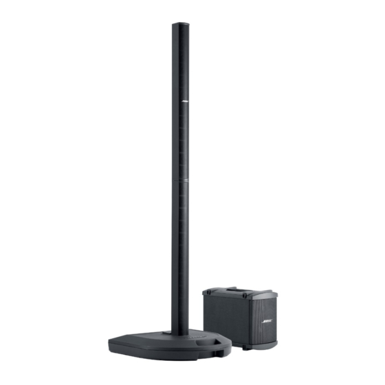
- Page 1 The Bose ® Personalized Amplification System™ Family of Products Owner’s Guide “A Mark of Quality” www.bose.com/musicians...
-
Page 2: Safety Information
CAUTION: No naked flame sources, such as lighted candles, should be placed on the apparatus. CAUTION: Where the mains plug is used as the disconnect device, such disconnect device shall remain readily operable. ©2005 Bose Corporation. No part of this work may be reproduced, modified, distributed or otherwise used without prior written permission. -
Page 3: Important Safety Instructions
Important Safety Instructions 1. Read these instructions. Information about products that 2. Keep these instructions. generate electrical noise 3. Heed all warnings. This equipment has been tested and found to 4. Follow all instructions. comply with the limits for a Class A digital device, pursuant to Part 15 of the FCC rules. -
Page 4: Instrucciones De Seguridad Importantes
©2005 Bose Corporation. Ninguna parte de esta obra puede reproducirse, modificarse, distribuirse o usarse de ninguna otra manera sin consentimiento previo por escrito. - Page 5 Adressez-vous à un réparateur qualifié. Les marquages de SÉCURITÉ présentés sur cette page sont situés sur les boîtiers de votre système. Ces marquages de SÉCURITÉ peuvent être situés sur les boîtiers du socle amplificateur PS1 Personalized Amplification System™ : Le symbole représentant un éclair avec une flèche à l’intérieur d’un triangle équilatéral est utilisé pour prévenir l’utilisateur de la présence d’une tension électrique dangereuse non isolée à...
-
Page 6: Table Of Contents
Contents Where to find... Setup ............... . Before you begin . -
Page 7: Setup
You will no longer wonder how you sound to your fellow musicians or to your audience. • Quick and easy setup – The Personalized Amplification System™ product is easy to carry and can be set up in minutes, not hours. This frees you from the time-consuming, draining, and frustrating effort required to properly set up conventional sound equipment. -
Page 8: Unpacking
Setup Unpacking Your Personalized Amplification System™ products are delivered to you in two cartons. One carton contains the PS1 power stand, AC power cord, R1 remote control with cable, protective plug, Owner’s and Quick Setup guides, PS1 carrying bag, CD-ROM, and a spare fuse. -
Page 9: Placing The Product In The Right Location For Your Performance
PS1 power stand connections. The following guidelines should get you started in setting up for a concert or show. Note: For more information on setting up your Personalized Amplification System™ product to achieve an individualized sound, visit www.bose.com/musicians... -
Page 10: Product Assembly
You should hear a soft click as the top section locks in place. CAUTION: Bose recommends using a quality surge suppressor on all electronic equipment. Voltage variations and spikes can damage electronic components in any system. -
Page 11: Disassembly
Setup Disassembly WARNING: Before disassembly, turn the power off and then remove the AC power cord and all other cables from the PS1 power stand. Remove the top L1 Cylindrical Radiator loudspeaker section Place one foot on the PS1 power stand to support your back. -
Page 12: Connecting A B1 Bass Module To The Ps1 Power Stand (Optional)
Setup Connecting a B1 bass module to the PS1 power stand (optional) jack on the PS1 power stand can adequately drive one or two B1 bass modules. B1 bass modules can be placed on the floor vertically or horizontally. Up to four modules can be stacked when placed horizontally (Figure 1). CAUTION: Do not connect more than two B1 bass modules to the B1 Bass Module (Amp 3 OUT) jack on the PS1 power stand. -
Page 13: Connecting Two B1 Bass Modules
Setup Connecting two B1 bass modules Connect the first B1 bass module to the PS1 power stand as shown in “Connecting one B1 bass module.” Insert one end of the second B1 bass module cable into the unused jack on the rear panel of the first B1 bass module. -
Page 14: Controls, Indicators And Connections
Line OUT ........XLR output for sending to external recording equipment or to conventional sound mixing consoles (for using the Bose approach in large venues). Insert .........A TRS line input/output for connecting to external equipment, such as digital effects processors. -
Page 15: Channel 3/4 Connections And Controls
Controls, Indicators and Connections Channel 3/4 connections and controls Line IN ........¼-inch phone connector unbalanced line input Level 0 to 12 ......Controls the source input level... -
Page 16: Power Amp Patch, Bass, Remote And Ac Power Connections
Bass - Line OUT ........ Balanced or unbalanced bass signal output for extended bass configurations Note: For more information on extended bass configurations, visit www.bose.com/musicians. Data IN ..........Digital data input. Used for updating product software Data OUT ........... Channel 1/2 digital output Remote.......... -
Page 17: R1 Remote Control Features
Controls, Indicators and Connections R1 remote control features HIGH LEVEL SIG / OL SIG / OL MASTER CH1/CH2 HIGH -12 to +12 ....Cuts (-) or boosts (+) high-frequency sounds CH1/CH2 MID -12 to +12 ....Cuts (-) or boosts (+) mid-frequency sounds CH1/CH2 LOW -12 to +12....Cuts (-) or boosts (+) low-frequency sounds CH1/CH2 LEVEL 0 to 12....Adjusts the channel’s volume level MASTER 0 to 12........Adjusts volume level of all channels... -
Page 18: Operating Instructions
Note: For more information on presets and amplifying the true sound of your instrument(s), please visit www.bose.com/musicians. Using input channels 3 and 4 The Channel 3 and 4 inputs are optimized for 0 dB line-level signals, such as the signals from an effects processor, mixer, or CD player. -
Page 19: Using An Effects Processor
Operating Instructions Using an effects processor IMPORTANT: When using an effects processor, determine and use the proper connection method (serial or parallel) for your application. Some effects MUST be hooked up in serial. Serial connection method With the serial method, the complete signal is routed directly into one or more effects processors. -
Page 20: Using A Serial Effects Connection With The Ps1 Power Stand
Operating Instructions Using a serial effects connection with the PS1 power stand Note: Connecting an effects unit in serial requires a TRS split “insert” cable (with a ¼-inch TRS connector on one side, and two mono ¼-inch phone connectors on the other). This type of cable is readily available at most musical instrument stores and on the Internet. -
Page 21: Using Parallel Effects Connection With The Ps1 Power Stand
Operating Instructions Using parallel effects connection with the PS1 power stand Note: Connecting an effects unit in parallel requires one ¼-inch unbalanced (instrument) cable, one mono ¼-inch phone (M) to dual mono ¼-inch phone (F) “Y” cable adaptor, and one TRS split “insert”... -
Page 22: Troubleshooting
• Plug your instrument into a different amplifier to make sure the instrument is working. Power LED is red while the • Please call Bose Live Music Customer Support at (877) 335-2673 for assistance. PS1 power stand is on House circuit breaker •... - Page 23 • Line OUT is not meant to be used with PS1 power stands. Some advanced or a mixer with only configurations are detailed online at www.bose.com/musicians. mic-level input Line OUT signals on • Check to make sure that the receiving device (mixer) is set up to receive a +4dBu level channels 1 and 2 are very signal.
-
Page 24: Customer Service
• If necessary, you may carefully vacuum the grille assembly of the L1 Cylindrical Radiator™ loudspeaker. Limited Warranty and Registration Your Personalized Amplification System™ product is covered by a limited transferable warranty. Details of the warranty are provided with your product. Register your products online at www.bose.com/register... -
Page 25: Technical Information
Technical Information Mechanical Dimensions • PS1 power stand: 26.0 W x 26.0 D x 5.0 H (66 cm x 66 cm x 12.7 cm) • L1 Cylindrical Radiator™ loudspeaker (each section): 3.5 W x 4.0 D x 43.0 H (8.9 cm x 10.5 cm x 109.2 cm) •... - Page 28 ©2005 Bose Corporation, The Mountain, Framingham, MA 01701-9168 USA 263976 AM Rev.03 CCM-001549 www.bose.com/musicians...