
Related Manuals for Audio Technica 200 Series


Summary of Contents for Audio Technica 200 Series
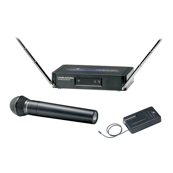
- Page 1 200 Series Professi o nal VHF Wirel e ss Systems ATW-251 Options ATW-251/G Guitar ATW-251/H Active ATW-251/L Presenter ATW-252 Vocal 0891 Installation and Operation...
- Page 2 Antennas Figure A (p. 3) Receiver Controls and Functions Figure B - Front panel controls and functions Figure C - Rear panel controls and functions...
-
Page 3: Transmitter Controls And Functions
Transmitter Controls and Functions Microphone Guitar Trimmer Trimmer (MT) (GT) ➞ ➞ Battery-Save Switch Battery Polarity (under screwdriver clip) Diagram Figure D Figure E Battery Polarity Diagram Battery-Save Switch Figure F Gain Trimmer Screwdriver Figure G Battery Condition Indicator Power Switch Battery Condition Off/Standby/On Indicator... -
Page 4: Installation And Operation
200 system. Because 200 Series packaging is designed to hold all versions of Notice to individuals with implanted cardiac pacemakers the system, some compartments in the carton are or AICD devices: intentionally left empty. -
Page 5: Receiver Installation
Receiver Installation A novel “dipole” antenna system on the receiver improves Location operation by providing a “ground” element in addition to the For best operation the receiver should be at least 3' (1 m) above usual “signal” element. Position the two antennas at 90° in the the ground and at least 3' (1 m) away from a wall or metal surface form of a “V,”... -
Page 6: Transmitter Setup
Transmitter Setup Battery Selection and Installation UniPak ™ Transmitter Input Connection An alkaline 9-volt battery is recommended. Make certain the Connect an audio input device (microphone or guitar cable) to the transmitter power switch is Off before installing or changing input connector on the bottom of the transmitter. -
Page 7: System Operation
System Operation Turn down the receiver volume control and the mixer/amplifier • Guitar: Adjusting input level level before starting up the wireless system. Do not switch on Gently turn only the “GT” (Guitar Trimmer) control all the way up the transmitter yet. (clockwise, toward “Hi”). - Page 8 System Operating Frequencies Frequency Selection RF Interference Each transmitter/receiver system operates on a single factory Please note that wireless frequencies are shared with other radio aligned, crystal-controlled frequency. Available frequencies are services. According to national regulations, “Wireless shown in the chart below. microphone operations are unprotected from interference from other licensed operations within the band.
-
Page 9: Specifications
Specifications † OVERALL SYSTEM UNIPAK TRANSMITTER ™ Operating Frequency VHF high band, 173 MHz to 175 MHz RF Power Output High: 10 mW; Low: 2 mW, typical Frequency Stability ±0.005% Spurious Emissions According to National Regulations ≥90 dB, A-weighted Modulation Mode Dynamic Range Maximum Deviation ±15 kHz... -
Page 13: Visit Our Website
DISCLAIMER Audio-Technica operates a policy of continuous development. Audio-Technica reserves the right to make changes and improvements to any of the products described in this document without prior notice. Under no circumstances shall Audio-Technica be responsible for any loss of data or income or any special, incidental, consequential or indirect damages howsoever caused.