Table of Contents
Advertisement
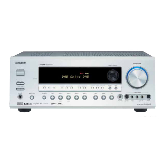
AV Receiver
TX-SR653E
Instruction Manual
Thank you for purchasing an Onkyo AV Receiver.
Please read this manual thoroughly before making
any connections and plugging it in.
Following the instructions in this manual will enable
you to obtain optimum performance and listening
enjoyment from your new AV Receiver.
Please retain this manual for future reference.
Contents
Introduction......................................2
Connections...................................20
First Time Setup.............................38
Basic Operations ...........................52
Advanced Operations....................66
Advanced Setup.............................70
Zone 2 .............................................76
Controlling Other Components ....80
Specifications ................................85
Troubleshooting.............................86
E
n
Advertisement
Table of Contents

Related Manuals for Onkyo TX-SR653E


Summary of Contents for Onkyo TX-SR653E
- Page 1 Advanced Operations....66 Advanced Setup......70 Zone 2 ..........76 Controlling Other Components ..80 Thank you for purchasing an Onkyo AV Receiver. Please read this manual thoroughly before making any connections and plugging it in. Following the instructions in this manual will enable Specifications ........85...
-
Page 2: Important Safety Instructions
WARNING: AVIS WARNING TO REDUCE THE RISK OF FIRE OR ELECTRIC RISK OF ELECTRIC SHOCK RISQUE DE CHOC ELECTRIQUE DO NOT OPEN NE PAS OUVRIR SHOCK, DO NOT EXPOSE THIS APPARATUS TO RAIN OR MOISTURE. The lightning flash with arrowhead symbol, within an equilateral triangle, is intended to alert the user to the CAUTION: presence of uninsulated “dangerous voltage”... -
Page 3: Precautions
Section 820-40 of the NEC which not user-serviceable. If you cannot turn on the AV provides guidelines for proper grounding and, in partic- receiver, contact your Onkyo dealer. ular, specifies that the cable ground shall be connected 3. Care—Occasionally you should dust the AV to the grounding system of the building, as close to the receiver all over with a soft cloth. -
Page 4: Supplied Accessories
AC outlet does not match with the plug on the AV GERMANY receiver’s power cord (adapter varies from country to declare in own responsibility, that the ONKYO product country). described in this instruction manual is in compliance with the... -
Page 5: Features
Dolby Laboratories. *2. “DTS,” “DTS 96/24,” “DTS-ES,” and “Neo:6” are trademarks of Digital Theater Systems, Inc. *3. “CinemaFILTER” is a trademark of Onkyo Corporation. “Xantech” is a registered trademark of Xantech Corporation. “Niles” is a registered trademark of Niles Audio Corporation. -
Page 6: Table Of Contents
Table of Contents Basic Introduction Important Safety Instructions ..................2 Precautions ........................3 Supplied Accessories.......................4 Features ..........................5 Table of Contents ......................6 Front & Rear Panels......................8 Remote Controller......................13 About Home Theater .......................19 Connecting the AV Receiver About AV Connections ....................20 Connecting Your Speakers.....................21 Connecting Antenna.......................23 Connecting Your TV or Projector ...................26 Connecting AV Components ..................27... - Page 7 Table of Contents —Continued Advanced Controlling Other Components Entering Remote Control Codes................... 80 Advanced Learning Commands from Other Remote Controllers..........83 Features Using Macros........................84 Advanced Setup Adjusting the Bass & Treble ..................70 Audio Adjust Functions....................70 Assigning Listening Modes to Input Sources ............. 72 Advanced IntelliVolume ........................
-
Page 8: Front & Rear Panels
Front & Rear Panels Front Panel TX-SR653E 0 A B C D MASTER VOLUME TUNING / PRESET STANDBY/ON ENTER STANDBY ZONE2 RETURN SETUP TONE STEREO LISTENING MODE DISPLAY DIGITAL INPUT RT/PTY/TP MEMORY TUNING MODE ZONE 2 LEVEL CLEAR VIDEO 4 INPUT... - Page 9 Front & Rear Panels —Continued SETUP button This button is used to access the onscreen setup menus that appear on the connected TV. MASTER VOLUME control (52) This control is used to adjust the volume of the AV receiver to MIN, 1 through 99, or MAX. PHONES jack (53) This 1/4-inch phone jack is for connecting a stan- dard pair of stereo headphones for private listening.
- Page 10 Front & Rear Panels—Continued Display The page numbers in parentheses show where you can find the main explanation for each item. RDS: This indicator lights up when the AV MUTING indicator (53) Receiver is tuned to a radio station that supports This indicator flashes while the AV receiver is RDS (Radio Data System).
-
Page 11: Rear Panel
Front & Rear Panels—Continued Rear Panel TX-SR653E 1B CD 9 JK IR IN 12 V TRIGGER OUT AV RECEIVER ZONE 2 MODEL NO. TX-SR 653E DIGITAL COAXIAL SURROUND BACK SURROUND SPEAKERS FRONT SPEAKERS SPEAKERS IN 1 ANTENNA FM 75 COMPONENT VIDEO... - Page 12 REMOTE CONTROL This (Remote Interactive) jack can be con- nected to an jack on another Onkyo AV compo- nent. The AV receiver’s remote controller can then be used to control that component. To use , you must make an analog audio connection (RCA) between the AV receiver and the other AV compo- nent, even if they are connected digitally.
-
Page 13: Remote Controller
Remote Controller Installing the Batteries Using the Remote Controller To use the remote controller, point it at the AV receiver’s To open the battery compartment, press remote control sensor, as shown below. the small hollow and slide off the cover. Remote control sensor AV receiver 30˚... -
Page 14: About The Remote Controller Modes
RECEIVER/TAPE mode is used to control the AV used to control up to nine different components. The receiver. It can also be used to control an Onkyo cassette remote controller has a specific operating mode for use recorder connected via with each type of component. - Page 15 Remote Controller—Continued For detailed information, see the pages in parentheses. SLEEP button (53) This button is used to set the Sleep function. STANDBY button (37) VOL [ ] button (52) This button is used to set the AV receiver to This button can be used to adjust the volume of the Standby.
- Page 16 Remote Controller—Continued TOP MENU button DVD Mode This button is used to select a DVD’s top menu. To set the remote controller to DVD mode, press the Arrow [ ] & ENTER buttons [DVD] REMOTE MODE button. These buttons are used to navigate DVD menus and the DVD player’s onscreen setup menus.
- Page 17 These buttons are used to enter track numbers and select the MD or CDR remote controller mode. to enter times for locating specific points in time. To control an Onkyo MD recorder or CD recorder, or a Arrow [ ] & ENTER buttons component made by another manufacturer, you must These buttons can be used with some components.
- Page 18 Remote Controller—Continued ON button* HDD Mode This button turns on the HDD-compatible compo- HDD mode is for controlling Onkyo’s next generation nent. HDD-compatible components. As of 2005, it can be Arrow [ ] and ENTER buttons* used with the Onkyo DS-A1 Remote Interactive Dock...
-
Page 19: About Home Theater
With DVDs you can enjoy DTS and Dolby Digital. With analog and digital TV you can enjoy Dolby Pro Logic IIx or Onkyo’s own DSP surround listening modes. Front left and right speakers These output the overall sound. -
Page 20: Connections
Connecting the AV Receiver AV Connection Color Coding About AV Connections RCA-type AV connections are usually color-coded: red, • Before making any AV connections, read the manuals white, and yellow. Use red plugs to connect right- supplied with your other AV components. channel audio inputs and outputs (typically labeled “R”). -
Page 21: Connecting Your Speakers
Connecting the AV Receiver—Continued Connecting a Powered Subwoofer Connecting Your Speakers Using a suitable cable, connect the AV receiver’s SUB- Speaker Configuration WOOFER PRE OUT to an input on your powered sub- woofer, as shown. If your subwoofer is unpowered and For the best surround sound experience, you should con- you’re using an external amplifier, connect the SUB- nect seven speakers and a powered subwoofer. - Page 22 If you’re using only one surround back speaker, connect • Make sure the metal core of the it to the left (L) SURROUND BACK SPEAKERS termi- wire does not have contact with nals. the TX-SR653E’s rear panel. Doing so may damage the AV Surround Surround Surround...
-
Page 23: Connecting Antenna
Connecting the AV Receiver—Continued Connecting the AM Loop Antenna Connecting Antenna The supplied indoor AM loop antenna is for indoor use This section explains how to connect the supplied indoor only. FM antenna and AM loop antenna, and how to connect commercially available outdoor FM and AM antennas. - Page 24 Connecting the AV Receiver—Continued Connecting an Outdoor FM Antenna Connecting an Outdoor AM Antenna If you cannot achieve good reception with the supplied If good reception cannot be achieved using the supplied indoor FM antenna, try a commercially available out- AM loop antenna, an outdoor AM antenna can be used door FM antenna instead.
-
Page 25: Which Connections Should I Use
COAXIAL input are not output by the analog TAPE jacks, not the VIDEO 1 and VIDEO 2 OUT V and S OUT. jacks. DVD player, Note: The TX-SR653E can be set to upconvert com- etc. posite video and S-Video input signals and output them Optical Coaxial... -
Page 26: Connecting Your Tv Or Projector
Connecting the AV Receiver—Continued Connecting Your TV or Projector IR IN 12 V TRIGGER OUT COAXIAL AV RECEIVER COMPONENT VIDEO ZONE 2 TX-SR 653E MODEL NO. IN 2 DIGITAL MONITOR COAXIAL IN 1 ANTENNA FM 75 COMPONENT VIDEO IN 3 IN 2 IN 1 ZONE 2... -
Page 27: Connecting A Dvd Player
Connecting the AV Receiver—Continued Connecting a DVD Player IR IN DIGITAL COAXIAL 12 V TRIGGER OUT AV RECEIVER ZONE 2 TX-SR 653E MODEL NO. IN 1 DIGITAL COAXIAL COMPONENT VIDEO IN 1 ANTENNA IN 1 FM 75 COMPONENT VIDEO IN 3 IN 2 IN 1 ZONE 2... - Page 28 Connecting the AV Receiver—Continued I Using a Multichannel Connection If your DVD player supports multichannel audio formats such as DVD-Audio, and it has a 5.1-channel analog audio output, you can enjoy DVD-Audio playback. Use a multichannel analog audio cable to connect the AV receiver’s DVD IN FRONT L/R, CENTER, SUR- ROUND L/R, and SUBWOOFER jacks to the 5.1- channel analog audio output on your DVD player, as...
-
Page 29: Connecting A Vcr For Playback
AV receiver. Video Connections Video Connections With the initial settings of the TX-SR653E, the VIDEO 1 input source is set for the COMPONENT VIDEO IN 2 • Use an S-Video cable to connect the AV receiver’s jacks. -
Page 30: Video Connections
Connecting the AV Receiver—Continued S-Video input, the recording VCR must be connected Connecting a VCR for Recording to an S-Video output. This section explains how to connect a VCR for VCR (recording) recording from a TV or another VCR. Video Connections AUDIO AUDIO •... -
Page 31: Audio Connections
Connecting the AV Receiver—Continued I Using Component Video Connecting Other Video Sources— If you connect to a component video input, you must Satellite, Cable, Set-top box, LD assign it (see page 43). Player, etc. Use a component video cable to connect the AV receiver’s COMPONENT VIDEO IN 2 or IN 3 jack to a Video Connections component video output on your video source, as shown. - Page 32 Connecting the AV Receiver—Continued I Using Analog Connections I Using S-Video If your video source doesn’t have a digital audio output, Use an S-Video cable to connect the AV receiver’s or you want to record from it, you’ll need to make the VIDEO 4 INPUT S VIDEO jack to the S-Video output following analog audio connection.
-
Page 33: Connecting A Cd Player
Connecting the AV Receiver—Continued Connecting a CD Player Connecting a Cassette Recorder I Using Optical or Coaxial Connections Use an analog audio cable to connect the AV receiver’s If you connect to a digital audio input, you’ll need to TAPE IN L/R jacks to the cassette recorder’s output, and assign it (see page 42). - Page 34 Connecting the AV Receiver—Continued I Using Optical or Coaxial Connections (playback only) If you connect to a digital audio input, you’ll need to assign it (see page 42). • Use an optical digital audio cable to connect one of the AV receiver’s OPTICAL DIGITAL IN jacks to the optical output on your recorder, as shown.
-
Page 35: Connecting A Turntable
Connecting the AV Receiver—Continued I Turntable with an MC (Moving Coil) Cartridge Connecting a Turntable Use an analog audio cable to connect an unused audio I Turntable with a Built-in Phono Preamp input on the AV receiver to the audio outputs on your Use an analog audio cable to connect an unused audio phono preamp. -
Page 36: Connecting The Power Cord Of Another Component
Another Component With (Remote Interactive) you can control your -compatible Onkyo CD player, DVD player, and so The AV receiver has an AC outlet on its rear panel for on with the AV receiver’s remote controller, as follows: connecting the power cord of another AV component. -
Page 37: Turning On The Av Receiver
Connecting the AV Receiver—Continued Turning On the AV Receiver • Before connecting the power cord, connect all your speakers and AV components. • Turning on the AV receiver may cause a momentary power surge that might interfere with other electrical equipment on the same circuit. -
Page 38: First Time Setup
First Time Setup This chapter explains the settings that you need to make before using the AV receiver. Automatic Speaker Setup Put the speaker setup micro- phone in the listening position, With the supplied speaker setup microphone, the Auto- and connect it to the SETUP MIC matic Speaker Setup function can measure the test tone jack. - Page 39 First Time Setup—Continued Press [ENTER]. Disconnect the speaker setup microphone. To cancel the automatic setup while it’s ENTER in progress, disconnect the micro- phone. The automatic speaker setup starts. The test tone is output by each speaker in turn, measured by the microphone, and the speaker settings set accordingly.
- Page 40 First Time Setup—Continued results confirmation screen, turn the volume up to an appropriate level and the frequency as high as it can go. And then turn on the Direct switch, if available. For fur- ther information, see the manual for the subwoofer. (Menus vary depending on country) When a speaker has a warning, its abbrevia- tion (e.g., L, R, and so on) appears.
-
Page 41: About The Onscreen Setup Menus
First Time Setup—Continued About the Onscreen Setup Menus The AV receiver is configured using onscreen setup menus, which are displayed on the TV that’s connected to either of the MONITOR OUT jacks. Because they appear on your TV, they’re large and clear, making setup a breeze. Submenus p. -
Page 42: Initial Setup
First Time Setup—Continued Initial Setup Examples: If you connect your DVD player to the Digital Input OPTICAL IN 2 jack, set “DVD” to “OPT2.” If you connect a component to a digital input jack, you must assign that jack to an input selector. For example, If you want to listen to audio from the if you connect your CD player to the OPTICAL IN2 component connected to the OPTICAL... -
Page 43: Component Video Setup
First Time Setup—Continued Component Video Setup VIDEO: Output composite video If you connect to a COMPONENT VIDEO IN, you must and S-Video sources from assign it to an input selector. For example, if you connect the COMPONENT VIDEO OUT. your DVD player to COMPONENT IN 3, you should assign it to the DVD input selector. -
Page 44: Tv Format Setup
First Time Setup—Continued TV Format Setup Press the [RECEIVER] button fol- lowed by the [SETUP] button. RECEIVER Here you can specify the TV format used in your area. The main menu appears onscreen. Press the [RECEIVER] button fol- lowed by the [SETUP] button. RECEIVER The main menu appears onscreen. -
Page 45: Speaker Setup
First Time Setup—Continued Speaker Setup Use the Up and Down [ buttons to select “1. Speaker Some of the settings in this section are set automatically Config,” and then press [ENTER]. ENTER by the Automatic Speaker Setup function (see page 38). The Speaker Config menu appears. - Page 46 First Time Setup—Continued Crossover Use the Up and Down [ buttons to select “d. Surround,” Use the Up and Down [ and then use the Left and Right ENTER buttons to select “g. Crossover,” ] buttons to select: and then use the Left and Right Small: Select if the surround left and ENTER ] buttons to select a...
- Page 47 First Time Setup—Continued Double Bass This setting is not set automatically by the Automatic Speaker Setup function (see page 38). With the Double Bass function, you can boost bass out- put by feeding bass sounds from the front left and right channels to the subwoofer.
-
Page 48: Speaker Distance
First Time Setup—Continued Speaker Distance Use the Up and Down [ buttons to select “a. Unit,” and This setting is set automatically by the Automatic then use the Left and Right [ Speaker Setup function (see page 38). ENTER ] buttons to select: feet: Select if you want to enter Here you can specify the distance from each speaker to distances in feet. -
Page 49: Speaker Level Calibration
First Time Setup—Continued Speaker Level Calibration Use the Up and Down [ buttons to select “3. Level Cali- This setting is set automatically by the Automatic bration,” and then press ENTER Speaker Setup function (see page 38). [ENTER]. The Level Calibration menu appears Here you can adjust the level of each speaker with the and the pink noise test tone is output by built-in test tone so that the volume of each speaker is the... -
Page 50: Equalizer Setting
First Time Setup—Continued Equalizer Setting Use the Left and Right [ buttons to select: This setting is set automatically by the Automatic Off: Tone off, response flat. Speaker Setup function (see page 38). ENTER Auto: The tone for each speaker is set automatically by the Here you can adjust the EQ of individual speakers. -
Page 51: Changing The Input Display
First Time Setup—Continued Changing the Input Display If you connect an -capable Onkyo MiniDisc recorder, CD recorder, or next generation HDD-compat- ible component to the TAPE IN/OUT or VIDEO 3 IN jacks, for to work properly, you must change this setting. -
Page 52: Basic Operations
Basic Operations Selecting the Input Source This section explains how to select the input source (i.e., the AV component that you want to listen to or watch). STANDBY INPUT MULTI CH T V CH MASTER VOLUME TUNING / PRESET TAPE TUNER STANDBY/ON T V VOL... -
Page 53: Setting The Display Brightness
Basic Operations—Continued Using the Sleep Timer TAPE TUNER With the sleep timer, you can set the AV receiver to turn T V VOL off automatically after a specified period. + 10 CLEAR - -/ --- INPUT SELECTOR MACRO Press the [RECEIVER] button, Press ZONE2 REMOTE MODE... -
Page 54: Displaying Source Information
Basic Operations—Continued B: The number of surround channels (2 means surround Displaying Source Information left and surround right). If there’s surround back You can display various information about the current channel information, this will be 3. input source as follows. C: LFE channel for subwoofer (1 means yes). -
Page 55: Using The Tuner
AM and FM. The TX-SR653E changes FM frequency in 0.05 MHz steps, 9 kHz steps for AM. In Manual Tuning mode, FM stations will be in mono. -
Page 56: Connecting The Dab Antenna
Basic Operations—Continued Connecting the DAB Antenna Using the DAB AUTOTUNE Screw the supplied DAB antenna onto the (TUNING MODE) DAB connector. Once the AV Receiver is ready for use, you’ll need MASTER VOLUME TUNING / PRESET STANDBY/ON to tune into a DAB station and adjust the position ENTER STANDBY of the DAB antenna to achieve the best possible... -
Page 57: Selecting The Station
Basic Operations—Continued Using the Auto Tune function manually: Displaying DAB Information At a later date, you may want to re-tune because you moved the AV receiver or because you want to receive a Press the [DISPLAY] button repeatedly to cycle through newly introduced multiplex. -
Page 58: Dab Setup
Basic Operations—Continued c. DRC Value DAB Setup Adjusts sound dynamic range so that louder signal may be reduced and soft one amplified during play. Press the [SETUP] button. It is useful when you enjoy play with the volume set to The main menu appears on the display. -
Page 59: Presetting Am/Fm Stations & Dab Stations
Basic Operations—Continued Selecting Presets Presetting AM/FM Stations & DAB Stations STANDBY INPUT 2, 4 MASTER VOLUME TUNING / PRESET STANDBY/ON T V CH MULTI CH ENTER STANDBY ZONE2 MASTER VOLUME TAPE TUNER TUNING / PRESET RETURN SETUP TONE STEREO LISTENING MODE DISPLAY DIGITAL INPUT RT/PTY/TP MEMORY TUNING MODE ZONE 2 LEVEL... -
Page 60: Using Rds
Basic Operations—Continued Program Types Used in Europe (PTY) Using RDS Type Display Description RDS only works with European models and only in areas where RDS broadcasts are available. None NONE No program type. News NEWS Reports on current events and I What is RDS? reports happenings. - Page 61 Basic Operations—Continued Displaying Radio Text (RT) To start the search, press [ENTER]. ENTER The AV receiver searches until it finds a station of the type you specified, at which point it stops briefly before con- MASTER VOLUME tinuing with the search. TUNING / PRESET STANDBY/ON ENTER...
-
Page 62: Selecting Listening Modes
Modes can be selected in the following order, depending on the input signal format: ➔ ➔ ➔ ➔ Pure Audio Direct Stereo Mono Surround (e.g., PLIIx, Neo:6, Dolby D EX, DTS/DTS 96/24, ➔ DTS-ES, and so on) Onkyo original DSP... - Page 63 Basic Operations—Continued The following table lists all the listening modes and shows which modes can be selected for each input signal format. Dolby D DTS/DTS 96/24*2 Analog, Multich Input signal format 1/0, DTS- PCM*1 3/2, 2/2 1/0,1+1 Other 3/2, 2/2 Other Source CD, TV, LD, VHS, MD,...
-
Page 64: About The Listening Modes
Basic Operations—Continued About the Listening Modes drama and natural sound enhance the listening experi- ence with CDs, movies, and games. With its built-in surround sound decoders and DSP pro- Dolby Pro Logic IIx has three modes of operation: grams, the AV receiver can transform your home listen- Movie mode for movies, Music mode for listening to ing room into a movie theater or concert hall. - Page 65 Basic Operations—Continued Onkyo Original DSP Modes DTS-ES Matrix This is DTS with an added surround back Orchestra channel for 6.1 surround sound. Use it to Suitable for classical or operatic music. The surround provide 6.1-channel surround playback channels are emphasized in order to widen the stereo with program material recorded in DTS 5.1...
-
Page 66: Advanced Operations Using The Late Night Function (Dolby Digital Only)
Advanced Operations Using the CinemaFILTER TAPE TUNER T V VOL With the CinemaFILTER, you can soften overly bright + 10 CLEAR movie soundtracks, which are typically mixed for repro- --/--- INPUT SELECTOR MACRO duction in a movie theater. ZONE2 REMOTE MODE CinemaFILTER can be used with the following listening RECEIVER RECEIVER... -
Page 67: Adjusting Individual Speaker Levels
Advanced Operations—Continued Using the DVD Analog Multichannel Input The DVD analog multichannel input is for connecting STANDBY INPUT components with a 5.1-channel analog audio output, such as a DVD player or MPEG decoder. MULTI CH T V CH See “Using a Multichannel Connection” on page 28 for MULTI CH connection information. -
Page 68: Recording
Advanced Operations—Continued Adjusting Individual Speaker Levels Configuration settings on page 45 are ignored, and sig- nals from the multichannel input are fed to the front left, You can adjust the level of individual speakers while front right, center, surround left, and surround right using the DVD analog multichannel input. - Page 69 Advanced Operations—Continued AV Recording Recording Separate AV Sources You can record AV input sources to an AV recording Here you can record audio and video from completely component (VCR, etc.) connected to the VIDEO 1 OUT, separate sources, allowing you to overdub audio onto VIDEO 2 OUT, or TAPE OUT.
-
Page 70: Advanced Setup
Advanced Setup Adjusting the Bass & Treble Audio Adjust Functions You can adjust the bass and treble for the front speakers, Here you can set listening mode-related settings and except when the Direct or Pure Audio listening mode is functions. selected. -
Page 71: Center Image
Advanced Setup—Continued The Audio Adjust functions are explained below. Neo:6 Music Mode Setting I Center Image Input Channel Settings The DTS Neo:6 Music listening mode creates 6-channel I Multiplex surround sound from 2-channel (stereo) sources. With This setting determines which channel is output from a this setting, you can specify by how much the front left stereo multiplex source. -
Page 72: Assigning Listening Modes To Input Sources
Advanced Setup—Continued Assigning Listening Modes to Input Use the Up and Down [ Sources buttons to select the signal for- mat that you want to set, and ENTER You can assign a default listening mode to each input then use the Left and Right [ source that will be selected automatically when you ] buttons to select a listening select each input source. -
Page 73: Intellivolume
Advanced Setup—Continued IntelliVolume Setting Preferences You can set the input level for each input source. This is This section explains the items on the Preference menu. useful if some of your AV components are louder or qui- Press the [RECEIVER] button fol- eter than others. -
Page 74: Digital Input Signal Formats
Onkyo component located in the same room. Auto (default): The format is detected automat- • If you change the AV receiver’s remote control ID, be ically. -
Page 75: Changing The Remote Controller's Id
Advanced Setup—Continued Changing the Remote Controller’s ID If several Onkyo components are used in the same room, the remote controller’s control codes may overlap with those of another component. To differentiate the remote controller’s control codes, you can change its ID to another number. -
Page 76: Zone 2
Zone 2 Using Only Speakers in Zone 2 Connecting Zone 2 With this connection method, you can use 5.1 surround With the Zone 2 function, you can enjoy one input sound in the main room and play a different AV source source in the main room and a different source in another in Zone 2. -
Page 77: Setting The Powered Zone 2
Zone 2—Continued Setting the Powered Zone 2 Use the Up and Down [ buttons to select “g. Powered To use Zone 2, you must make this setting. It enables the Zone 2,” and use the Left and speakers connected to the ZONE 2 SPEAKERS termi- ENTER Right [ ] buttons to select:... -
Page 78: Using Zone 2
Zone 2—Continued Using Zone 2 To set Zone 2 to the same source as the main room, press the [ZONE 2] button Here you can turn on Zone 2, select an input source, and repeatedly to display adjust the volume. “Zone 2 Sel: Source.”... -
Page 79: Using The Remote Control In Zone 2
Zone 2—Continued Using the 12V Trigger Using a Multiroom Kit with a Cabinet When Zone 2 is turned on, the ZONE 2 12V TRIGGER In the following diagram, an IR receiver picks up the OUT outputs 12 volts (100 milliamperes max). By con- infrared signals from the remote controller and feeds necting this jack to the 12-volt trigger input on, say, a them to the AV receiver in the cabinet via the connecting... -
Page 80: Controlling Other Components Entering Remote Control Codes
VIDEO OFF • The HDD remote mode can only be used with the L NIGHT CINE FLTR Onkyo DS-A1 Remote Interactive Dock at this RC-623M time. • The [DVD] and [CD] REMOTE MODE buttons are preprogrammed for use with Onkyo DVD players and CD players respectively. -
Page 81: Resetting The Remote Controller
If you want to control an Onkyo component by pointing the remote controller directly at it, or you want to control an Onkyo component that’s not connected via , use... - Page 82 Controlling Other Components—Continued • To control another component, point the remote controller at it and use the buttons explained below. (You must select the appropriate remote control mode first.) With some AV components, certain buttons may not work as expected, and some may not work at all. I Controlling a TV I Controlling a VCR I Controlling a Satellite or...
-
Page 83: Learning Commands From Other Remote Controllers
• Remote controller buttons such as Play, Stop, Pause, and so on are preprogrammed with commands for While holding down the REMOTE controlling Onkyo CD players, cassette decks, and MODE button for the mode in DVD players. However, they can learn new com-... -
Page 84: Using Macros
Controlling Other Components—Continued Using Macros While holding down the REMOTE MODE button for the mode you REMOTE MODE You can program the remote controller’s MACRO but- want to start with, press MACRO RECEIVER tons to perform a sequence of actions. TAPE/AMP button [1], [2], or [3]. -
Page 85: Specifications
Specifications Amplifier Section General Power Output Power Supply AC 230-240 V, 50 Hz 2 channel driven: 125 W + 125 W Power Consumption 630 W (6 Ω, 1 kHz, DIN) Stand-by Power 225 W + 225 W (3 Ω, Front) Dynamic Power Consumption 0.2 W... -
Page 86: Troubleshooting
Music listening mode with a mono source, such as an Remove the power cord from the wall outlet immedi- AM radio station or mono TV program, the sound is ately and contact your Onkyo dealer. concentrated in the center speaker. • Make sure the speakers are configured correctly Audio (page 45). - Page 87 Troubleshooting—Continued The subwoofer produces no sound? About DTS signals • When you play source material that contains no infor- • When DTS program material ends and the DTS bit- mation in the LFE channel, the subwoofer produces stream stops, the AV receiver remains in DTS listen- no sound.
- Page 88 • Make sure to set the same ID on both the AV receiver and remote controller (pages 74 and 75). Can’t control other components? • If it’s an Onkyo component, make sure that the cable and analog audio cable are connected properly. Connecting only an cable won’t work (page 36).
- Page 89 Direct, or Pure Audio. When you disconnect the head- phones, the previous listening mode will be resumed. Onkyo is not responsible for damages (such as CD The speaker volume cannot be set as required? rental fees) due to unsuccessful recordings caused by the unit’s malfunction.
- Page 92 Units 2102-2107, Metroplaza Tower I, 223 Hing Fong Road, Kwai Chung, N.T., HONG KONG Tel: 852-2429-3118 Fax: 852-2428-9039 http://www.ch.onkyo.com/ D0509-1 SN 29344097 (C) Copyright 2005 ONKYO CORPORATION Japan. All rights reserved. * 2 9 3 4 4 0 9 7 *...