Table of Contents
Advertisement
SERVICE MANUAL
SERVICE MANUAL
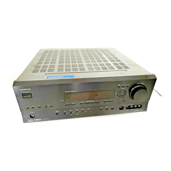
AV RECEIVER
MODEL
STANDBY/ON
POWER
STANDBY
ON
OFF
REC OUT
ZONE
2
OFF
LEVEL
DISPLAY
RT/PTY/TP
PHONES
AUDIO
DVD
VIDEO 1
VIDEO 2
SELECTOR
VCR 1
VCR 2
Black, Golden and Silver models
BMDD,BMDC,SMDC
BMPP,SMPP,BMPA,SMPA
BMWT,GMWT,GMWR,GMWQ
GMGK
SAFETY-RELATED COMPONENT
WARNING!!
COMPONENTS IDENTIFIED BY MARK
SCHEMATIC DIAGRAM AND IN THE PARTS LIST ARE
CRITICAL FOR RISK OF FIRE AND ELECTRIC SHOCK.
REPLACE THESE COMPONENTS WITH ONKYO
PARTS WHOSE PART NUMBERS APPEAR AS SHOWN
IN THIS MANUAL.
MAKE LEAKAGE-CURRENT OR RESISTANCE
MEASUREMENTS TO DETERMINE THAT EXPOSED
PARTS ARE ACCEPTABLY INSULATED FROM THE
SUPPLY CIRCUIT BEFORE RETURNING THE
APPLIANCE TO THE CUSTOMER.
TX-SR601/E
AUDIO
ADJUST
SETUP
TUNI NG
PRESET
LISTENING MODE
DIRECT
STEREO
SURROUND
DSP
MEMORY
FM MODE
CLEAR
VIDEO 3
VIDEO 4
TAPE
TUNER
C D
120V AC, 60Hz
230-240V AC, 50Hz
120/220-230V AC, 50/60Hz
220-230V AC, 50Hz
ON THE
Page 1
Ref. No. 3773
MASTER VOLUME
RETURN
ENTER
VIDEO
4
INPUT
DIGITAL
S VIDEO
VIDEO
L
AUDIO
R
TX-SR601/E
062003
Advertisement
Table of Contents

Related Manuals for Onkyo TX-SR601/E


Summary of Contents for Onkyo TX-SR601/E
- Page 1 COMPONENTS IDENTIFIED BY MARK ON THE SCHEMATIC DIAGRAM AND IN THE PARTS LIST ARE CRITICAL FOR RISK OF FIRE AND ELECTRIC SHOCK. REPLACE THESE COMPONENTS WITH ONKYO PARTS WHOSE PART NUMBERS APPEAR AS SHOWN IN THIS MANUAL. MAKE LEAKAGE-CURRENT OR RESISTANCE...
-
Page 2: Specifications
TX-SR601 Specifications (TX-SR601/601E) AMPLIFIER SECTION TUNER SECTION Continuous average power output (FTC) 85 W per channel min. RMS at 8 Ω, All channels: Tuning range: 2 channels driven from 20 Hz to 20 USA & Canadian models: 87.50–108.00 MHz (100-kHz steps) kHz with no more than 0.08% total Other area models: 87.50–108.00 MHz (50-kHz steps) - Page 3 TX-SR601/E SERVICE PROCEDURES 1. Replacing the fuses 4.Setting the voltage selector (Worldwide models only) This symbol located near the fuses indicates that the fuse used is fast operating type. For continued protection against Worldwide models are equipped with a voltage selector to conform fire hazard, replace with same type fuse.
-
Page 4: Front Panel Facilities
TX-SR601 Front panel facilities Here is an explanation of the controls and displays on the front panel of the TX-SR701/701E/601/601E. Front panel <TX-SR701E> MASTER VOLUME AUDIO ADJUST SETUP RETURN STANDBY/ON TUNI NG PRESET POWER STANDBY LISTENING MODE REC OUT ZONE LEVEL DISPLAY RT/PTY/TP... - Page 5 TX-SR601 Front panel facilities MEMORY button Press to assign the radio station that you are currently tuned into to a preset channel or press to delete a previously preset station. POWER switch (for all models other than USA and Canadian models, and Australian models) FM MODE button Press to turn on and off the main power supply for the TX-SR701/ 701E/601/601E.
- Page 6 TX-SR601 Front panel facilities Input source buttons (DVD, VIDEO 1–4, TAPE, TUNER, CD, and PHONO (TX-SR701/701E only)) These buttons are used to select the input source. Press these buttons to select the input source for the main zone. To select the input source for the remote zone (Zone 2) or recording out (Rec Out), first press the ZONE 2 or REC OUT button, and then press the desired input source button.
-
Page 7: Front Panel Display
TX-SR601 Front panel facilities Front panel display MUTING indicator Multi function display Flashes when the mute function is turned on. During normal operation, shows the current input source and volume. When the FM or AM input is selected, shows the frequency and preset number. -
Page 8: Rear Panel
TX-SR601 Rear panel TX-SR701/701E REMOTE When using Connecting antennas CONTROL the Zone 2 COMPONENT VIDEO LINE OUT 12V TRIGGER ZONE 2 Connecting speakers AC OUTLETS INPUT/OUTPUT terminal terminals CAUTION: SPEAKER IMPEDANCE ANTENNA FM 75 6 OHMS MIN. /SPEAKER COMPONENT VIDEO SURROUND CENTER ZONE 2... -
Page 9: Remote Controller
Press the ANGLE button to select a camera angle when playing a DVD-Video with multiple angle playback. Press the SUBTITLE button to select a subtitle language when playing a DVD-Video. CD/TAPE/DVD/MD operation buttons Press to operate other Onkyo components connected to the TX- SR701/701E/601/601E using the terminals. Page 9... - Page 10 TX-SR601 Remote controller INPUT SELECTOR buttons MUTING button Press to select an input source. Same as the input selector buttons on the front panel of the TX- AUDIO ADJUST button SR701/701E/601/601E. The input source for each button is given here. DVD:DVD, CD:CD, V1:VIDEO1,...
-
Page 11: Supplied Accessories
TX-SR601 Supplied accessories Check that the following accessories are supplied with the TX-SR701/701E/ The following accessories may be available depending 601/601E. on the area which it was purchased. AM loop antenna × 1 FM indoor antenna × 1 Conversion plug × 1 (Use this plug if the power cord plug of the TX- SR701/701E/601/601E does not fit your AC outlet. -
Page 12: Exploded View
TX-SR601 EXPLODED VIEW P901 P101 35 U12 F903 P6931 F901 F6901 Q6050 F902 F6902 P7501 Q6060 Q6055 P7502 Q6065 F9501 T901 Except 120V and Page 12 Australian models... -
Page 13: Block Diagram
TX-SR601/E BLOCK DIAGRAM DIGITAL AUDIO INPUT FRONT DIGITAL AUDIO OUTPUT OPTICAL OPTICAL COAXIAL 12.288MHZ 13.5MHZ OPTICAL 1 OPTICAL 2 VLSC DD/DTS BASS- DECODER SRAM CS42528 MANAGE CY7C1019 (1/3) MENT ONLY DTR & MJJ MB86D42PFV MB86344BPFV DAUX VLSC 192/24 192/24 ONLY DTR & MJJ... - Page 14 TX-SR601/E BLOCK DIAGRAM HEADPHONE MULTICHANNEL INPUT SW C SR SL HPEN BD3811K1 (2/2) MASTER VOLUME Power Amplifier BASS/TREBLE MUTE BOOST +29dB SW->L BYPASS BASS/TREBLE MUTE +29dB PREOUT SW->R BYPASS MCSL MUTE +29dB SUBWOOFER MCSR FRONT SPEAKERS RIGHT MUTE +29dB LEFT...
-
Page 15: Schematic Diagram
TX-SR601/E SCHEMATIC DIAGRAM 1 Front panel section NADIS-7960 Q7501 HNA-16MM39T P46/FIP38 P47/FIP39 FIP18 62 61:FIP19 P50/FIP40 FIP17 63 P51/FIP41 FIP16 64 P52/FIP42 FIP15 65 P53/FIP43 FIP14 66 P54/FIP44 Q7502 FIP13 67 P55/FIP45 FIP12 68 UPD78F0233GC P56/FIP46 FIP11 69 P57/FIP47 FIP10 70... - Page 16 TX-SR601/E SCHEMATIC DIAGRAM 1 Front panel section P7502A TO NAPS-7975 (SCH-5) NAVD-7986 -26V AC6V C7535 473Z 5.6V R2501 V4-L V4-R R2502 C7505 473Z NAETC-7961 P7705 HEADPHONES HPDET HPDET HPR2 HPL2 HPR2 L7703 022M RL7701 L7704 HPL2 C7701 022M 102J C7703...
-
Page 17: Driver Section
TX-SR601/E SCHEMATIC DIAGRAM 3 Driver section TO NADG-7952 NAAF-7984 Z2LPO Q5801 P308C SLPO KTC3199 Z2RPO OR 2SC1740S SRPO RL5801 *C5030~C5035 : D MODEL NONE R5163 53.0V 120 (1/4W) R5113 R5183 52.2V Q5033 (1/4W) C5033 R5093 51.7V 101K 100K 1.1V C5053... - Page 18 TX-SR601/E SCHEMATIC DIAGRAM 3 Driver section TO NAAF-7983 TO NADG-7952 TO NADG-7952 TO NAAF-7985 (TX-SR601/601E/DTR-5.4) (SCH-2) (SCH-5) (SCH-5) (SCH-2) JL5802B JL5801B P308A P309A DTR-6.4/5.4 C5128 Q5078 10/50 R5218 R5208 Q5068 RN1241 C5127 RN1241 Q5077 C5129 10/50 R5217 R5219 R5207 Q5079...
- Page 19 TX-SR601/E SCHEMATIC DIAGRAM 2 P304 FROM FRONT FRONT VIDEO-4 IN P107B TO N JL7503B DSP and main microprocessor R302 102K TU/PH/CDL C363 C362 TU/PH/CDR 10/16 10/16 R303 R304 TAPE IN C366 332J R305 C367 332J R344 C301 102K C368 563J...
- Page 20 TX-SR601/E 78M12HF Q9501 R9501 12 SCHEMATIC DIAGRAM 2 +12VA Q101 R9506 C9509 C9507 (1W) KTC3875-GR 220/16 R9505 /2SC2712 104Z 104Z C9508 C9501 C9510 TO NAETC-7982 P105B TO TUNER PACK 220/10 +24V TO NAETC-7982 P101A C9502 220/16 47/35 Q9512 79M05FA Q101...
- Page 21 TX-SR601/E SCHEMATIC DIAGRAM 1-1 Front panel section NAETC-7961 P7705 HEADPHONES HPDET HPR2 HPL2 L7703 022M L7704 C7701 022M 102J C7703 C7702 L7701 C7704 221K 102J 022M 101J P7706 E7701 NADG-7964 L2601 U2601 0.22M R2601 NAVD-7986 R2501 V4-L V4-R R2502 Page 21...
-
Page 22: Power Amplifier Section
TX-SR601/E SCHEMATIC DIAGRAM 4 Power amplifier section NAAF-7966 Q6033 53.0V R6163 R6083 Q6053 R6033 1.1V (1/4W) 1.0V Q6073 R6143 0.6V 0.6V R6003 R6073 5.6K R6103 (1/4W) R6013 0.22 P6083 Q6013 X2(2W) NF-SL 3.9K NF-F R6153 Q6023 -0.6V C6043 R6093 C6053... - Page 23 TX-SR601/E SCHEMATIC DIAGRAM 4 Power amplifier section Q6030 53.0V R6160 R6080 R6030 1.1V Q6050 (1/4W) NAETC-7967/7973 1.0V Q6070 R6140 0.6V R6000 0.6V THERMAL PROT. 5.6K THERMAL SENS. R6381 R6380 +24V R6070 R6100 R6010 +24V 0.22 P6080 3.9K (1/4W) NF-FL X2(2W) -0.3V...
- Page 24 TX-SR601/E SCHEMATIC DIAGRAM 5 Power supply and speaker terminal sections NAPS-7975 C9003 NAAF-7985 D9001 D9002 1000/35 C9001 334J TX-SR601 ONLY D9501-9503: P6813 RL1N4003 C9004 D9003 470/35 C9002 334J +24V D9004 PREOUT -24V Q9001 +12V R9001 D9005 +5.6S D9010 C9005 C9011...
- Page 25 TX-SR601/E SCHEMATIC DIAGRAM 5 Power supply and speaker terminal sections NAAF-7968 NAAF-7985 L6800 S1.3C SPEAKER OUT C6600 103Z R6800 22 D6600 TX-SR601 ONLY R6810 22 ZONE2 L C6856 P6813 102J RL6600 ZONE2 R C6857 PREOUT 102J C6850 102J L6801 S1.3C...
- Page 26 TX-SR601/E SCHEMATIC DIAGRAM 6 Video and bus line sections P2201B E2201 P2210B NAVD-7954 Q2201 RN1401 D2201 C2202 102K RL2201 P2203 P2203 RL2202 NJM4565M-D C2251 2.2/50 Q2255 Q2257 KRA102S P2203 R2275 220K NJM4565M-D C2271 104Z C2252 2.2/50 Q2255 C2201 102K P2209...
- Page 27 TX-SR601/E SCHEMATIC DIAGRAM 6 Video and bus line sections E201 P207B P208B NAVD-7953 C204 104Z L201 U201 OPT2 022K C205 104Z R223 U202 C245 OPT1 R224 470/6.3 C206 U203 104Z OPTOUT C203 C248 47/16 R216 P201 L210 470/6.3 022K Q211...
-
Page 28: Printed Circuit Board View
TX-SR601/E PRINTED CIRCUIT BOARD VIEW 7 J2909 P2201A P2210A J2924 P2202A J2910 P2212A J2918 J2908 R2909 J2907 J2956 J2946 J2954 J2916 C2903 J2952 P2001A P208A P207A J2945 NCETC-7982 25137982 J2933 J2938 J2925 J2915 Q2903 J2926 J2913 J2927 J2935 J2911 J2912... -
Page 29: Wiring View
TX-SR601/E WIRING VIEW P925A P926A SPEAKER Korean model only P902A NCETC- 7978 TERMINAL SOLDERING SIDE AC OUTLET TERMINAL PC BOARD PC BOARD(NAETC-7978) (NAAF-7968) JL6804B JL6803B JL6805B E921 S902 THERMAL P925 P926 PRIMARY NCETC-7967 DETECTOR P902 CIRCUIT PC BOARD JL6402B P917... - Page 30 TX-SR601/E WIRING VIEW MAIN CONNECTOR PC BOARD P302 P300 P301 P303 (NAETC-7982) JL5802C CIRCUIT PC BOARD (NADG-7952) P309 PREOUT. P308 TERMINAL PC BOARD (NAAF-7985) P201 DRIVER P206 P202 U203 U201 P204 U202 P205 CIRCUIT PC BOARD NAAF-7984) VIDEO P101A CIRCUIT...
- Page 31 TX-SR601/E PRINTED CIRCUIT BOARD VIEW 1-2 Front panel section VIDEO1 VIDEO2 VIDEO3 S7635 S7636 S7637 PURE-AUDIO S7644 S7633 S7634 PURE-AUDIO SELECTOR D7582 AUDIO D7584 PURE-AUDIO J7507 PTY/TP DIRECT REC-OUT DISPLAY DIMMER S7642 S7643 S7645 S7646 S7647 S7632 S7631 S7621 SPK-A...
- Page 32 TX-SR601/E PRINTED CIRCUIT BOARD VIEW 1-2 Front panel section DEO3 VIDEO4 7637 S7638 S7626 S7627 S7629 S7628 TAPE TUNER P7601 TUNER TAPE PHONO VOLUME PC BOARD STEREO SURROUND MEMORY FM-MODE S7622 S7623 S7624 S7625 S7619 JL7501B NCSW-7962 25137962 S7618 ENTER...
- Page 33 TX-SR601/E PRINTED CIRCUIT BOARD VIEW 3 Power amplifier section section Q5035 C5005 R5235 R5195 J5087 R5005 R5225 C5015 J5089 R5045 R5185 C5115 J5086 R5165 Q5075 R5015 R5135 R5215 R5025 J5081 Q5065 C5095 C5045 J5084 R5105 Q5055 R5085 R5075 Q5015 R5175...
- Page 34 TX-SR601/E PRINTED CIRCUIT BOARD VIEW 2 DSP and main microprocessor DSP CIRCUIT PC BOARD(NADG-7952) Page 34...
- Page 35 TX-SR601/E PRINTED CIRCUIT BOARD VIEW 2 DSP and main microprocessor DSP CIRCUIT PC BOARD(NADG-7952) Page 35...
- Page 36 TX-SR601/E PRINTED CIRCUIT BOARD VIEW 2 DSP and main microprocessor R 9505 Q9502 Q9502 Q9502 C390 DSP CIRCUIT PC BOARD(NADG-7952) Page 36...
- Page 37 TX-SR601/E PRINTED CIRCUIT BOARD VIEW 2 DSP and main microprocessor LS/R LS/R LS/R LS/R LS/R SBL/S SBL/S DSP CIRCUIT PC BOARD(NADG-7952) Page 37...
- Page 38 TX-SR601/E PRINTED CIRCUIT BOARD VIEW 1-1 NCDG-7964 JL7502B P7705 HPL2 U2601 HPR2 HPDET Component side 25137961 NCETC-7961 FRONT OPTICAL INPUT PC BOARD Component side (NADG-7964) HEADPHONE TERMINAL PC BOARD(NAETC-7961) C2602 C7702 L7703 R2601 Soldering side L7701 FRONT OPTICAL INPUT PC BOARD...
- Page 39 TX-SR601/E PRINTED CIRCUIT BOARD VIEW 3 Power amplifier section section Q6012 Q6011 Q6010 Q6052 Q6061 Q6051 Q6062 Q6060 Q6050 R6092 R6091 R6090 J6025 J6147 R6510 J6134 J6129 J6105 J6091 J6073 J6048 J6026 J6130 J6074 J6022 J6141 J6108 J6071 J010A J011A...
- Page 40 TX-SR601/E PRINTED CIRCUIT BOARD VIEW 3 Power amplifier section section Q6015 Q6014 Q6013 Q6054 Q6053 Q6065 Q6055 Q6064 Q6063 Q6062 R6094 R6093 J6147 R6095 J6185 J6180 J6174 J6170 J6165 J6156 J6155 J6148 C6524 J6181 J6166 J6149 J6177 J6162 J6141 J6205...
- Page 41 TX-SR601/E PRINTED CIRCUIT BOARD VIEW 5 WHITE BLACK WHITE BLACK BLUE BLACK GREEN BLACK P6803 P6802 BLACK BLACK GREY BLACK BROWN BLACK J16A J15A P6803 C6856 C6840 P6802 P6804 C6846 C6853 C6842 RL6604 C6843 RL6600 C6851 C6852 RL6603 C6857 C6845...
- Page 42 TX-SR601/E PRINTED CIRCUIT BOARD VIEW 5 D9003 C9004 25137975 E9001 JL9502B J9017 NCPS-7975 C9004 C9003 D9004 J9003 R9007 J9008 JL9501A D9001 +13VS J9013 C9002 C9001 +24V RLGND D9002 MPUGND J9007 +12V D9011 +5.6S R9001 P7502B J9005 D9010 +13VS J9002 J9001...
- Page 43 TX-SR601/E PRINTED CIRCUIT BOARD VIEW 6 VIDEO CIRCUIT PC BOARD P209A (NAVD-7953) 25137 NCVD-7 NCVD 7 NCVD 7 COMPONENT VIDEO PC BOARD (NAVD-7954) Page 43...
- Page 44 TX-SR601/E PRINTED CIRCUIT BOARD VIEW 6 VIDEO CIRCUIT PC BOARD (NAVD-7953) R2256 2 256 COMPONENT VIDEO PC BOARD (NAVD-7954) Page 44...
- Page 45 TX-SR601/E IC BLOCK DIAGRAMS AND DESCRIPTIONS TC9274F-020 (Analog switch) R - c h S5 S6 S7 S8 S9 S10 S11 S12 S13 S14 S15 33 32 31 30 29 28 27 26 25 24 23 S5 S6 S7 S8 S9 S10 S11 S12 S13 S14 S15...
- Page 46 TX-SR601/E IC BLOCK DIAGRAMS AND DESCRIPTIONS BD3811K1(6ch Volume with 8ch input selector) No. Terminal Description INDSPSL DSP surround Lch input terminal INDSPC DSP center input terminal INDSPSW DSP sub woofer input terminal I N 3 1 T N F 2...
- Page 47 TX-SR601/E IC BLOCK DIAGRAMS AND DESCRIPTIONS LC74763-9836(On-screen and controller) 8 BITS SERIAL LATCH PARALLEL COMMAND CONVERSION DECODER INDICATOR HORIZONTAL HORIZONTAL VERTICAL ON/OFF RAM WRITE VERTICAL SCLK CHARACTER INDICATION INDICATION INVERSION CHARACTER CONTROL ADDRESS POSITION POSITION CONTROL SIZE SIZE REGISTER REGISTER...
-
Page 48: Ic Block Diagrams And Descriptions
TX-SR601/E IC BLOCK DIAGRAMS AND DESCRIPTIONS LC72723M(RDS demodulator) PIN ARRANGEMENT BLOCK DIAGRAM V REF RDS-ID/READY V REF FLOUT MPXIN 15 RDCL Vdda Vddd Vdda 14 RDDA CLOCK RECOVERY Vssa LC72723 13 RST REFERENCE (57kHz) (1187.5Hz) VOLTAGE LC72723M FLOUT 12 MODE... - Page 49 TX-SR601/E IC BLOCK DIAGRAMS AND DESCRIPTIONS BD3812F(Audio Sound Processor) OUT1 1ch input 1ch output AGND1 OUT2 Analog ground 2ch output 2ch input Serial data select AGND2 DGND Analog ground Comparator ground MUTE (-)Power supply Mute AGND3 LOGIC Analog ground Serial data...
- Page 50 TX-SR601/E IC BLOCK DIAGRAMS AND DESCRIPTIONS TC9164AF(Function switch) 74HCU04F(Hex Inverters) COM1 COM1 (TOP VIEW) Truth table COM2 COM2 TC74VHCT00AFT(2-input NAND gate) COM3 COM3 DATA SHIFT REGISTER Pin No. Symbol Function Negative power supply Ground Positive power supply 2,3,4,6,7,8,10,11 S1~S8 Input/output terminals...
- Page 51 TX-SR601/E IC BLOCK DIAGRAMS AND DESCRIPTIONS CS42518(192 kHz 8-Ch Codec with S/P DIF Receiver) 64 63 62 61 60 59 58 57 56 55 54 53 52 51 50 49 RXP1/GPO1 CX-SDIN1 RXP2/GPO2 CX-SCLK RXP3/GPO3 CX-LRCK RXP4/GPO4 RXP5/GPO5 DGND RXP6/GPO6...
-
Page 52: Connection Diagram
TX-SR601/E SUB-MICROPROCESSOR CONNECTION DIAGRAM Q7501 FL TUBE HNA-16MM39T FIP19 P46/FIP38 40 FIP18 P47/FIP39 39 FIP17 P50/FIP40 38 FIP16 P51/FIP41 37 FIP15 P52/FIP42 36 FIP14 P53/FIP43 35 FIP13 P54/FIP44 34 FIP12 P55/FIP45 33 FIP11 P56/FIP46 32 Q7502 FIP10 P57/FIP47 31 FIP9... - Page 53 TX-SR601/E MAIN MICROPROCESSOR CONNECTION DIAGRAM Q205 Q201~Q203 VIDEO VIDEO CONTROL SELECTOR SWITCH SWITCH TC9164AF NJM2595M 12V TRIGGER ZONE 2 Q204 ON SCREEN DEMODULATOR LC74763 Q6701~3 ABNORMAL VOLTAGE/ CURRENT DETECTOR Y C S E P D A 1 0 0 Q7505...
- Page 54 TX-SR601/E MAIN MICROPROCESSOR CONNECTION DIAGRAM TUNER PACK Q2253,4 Q2272,3 FRONT/CENTER/SURROUND ZONE 2 MUTE BACK/SUBWOOFER CH. RL901 PREOUT PREOUT Q 9 2 1 P O W E R R E L A Y Q9503 Q5063,4,5073,4 Q400,3 -12V Q9504 ZONE 2 OUTPUT...
- Page 55 TX-SR601/E TERMINAL DESCRIPTION SUB MICROPROCESSOR Pin No. Symbol I/O Description Pin No. Symbol I/O Description Power supply terminal. Connect to 5V. Segment output terminal of P22. Ground terminal. Segment output terminal of P21. Ceramic oscillator connection terminals for main system.
- Page 56 TX-SR601/E MAIN MICROPROCESSOR TERMINAL DESCRIPTION Symbol I/O Description DSP1BST O Boot strap output pin for first DSP IC. ~DSP1HCS O Serial communication clock output pin for Q302 and Q310. ~DSP1HACN Acknowledge input pin for first DSP IC. DSP1GP8 O PCM information output pin for first DSP IC.
- Page 57 TX-SR601/E MAIN MICROPROCESSOR TERMINAL DESCRIPTION Symbol I/O Description HPRL O Headphone relay control output pin YCSEPCLK O Not used. OSDCS O Serial communication chip select output pin for OSD IC Q204. OSDDA O Serial communication data output pin for OSD IC.
-
Page 58: Adjustment And Confirmation Procedures
TX-SR601/E ADJUSTMENT AND CONFIRMATION PROCEDURES 2 3. Confirmation of Current detection circuit Set the unit to "Test-1-00". Connect the differentiating circuit and apply the 200Hz square signal to DVD INPUT terminal of each channel. Adjust the attenuator or Volume so that the output level becomes 35V p-p. - Page 59 TX-SR601/E ADJUSTMENT AND CONFIRMATION PROCEDURES 1 Idling current adjustment Before Idling adjustment, turn the trimming resistors R6040 to R6045 to counter clockwise. Connect the DC voltmeter to sockets P6080 to P6085. After turn POWER to ON, adjust the trimming resistors R6040, R6041 and R6042 so that the reading of voltmeter becomes 2.5 mV.
-
Page 60: Packing Procedures
TX-SR601/E PACKING PROCEDURES Bottom Except 120V model Accessary bag Speaker Cable Put the label 81 between page 2 and page 3 of instruction manual E. Page 60... -
Page 61: Exploded View Parts List
EXPLODED VIEW-PARTS LIST REF.NO. PART NO. DESCRIPTION <B>:Black model only <S>:Silver model only 27111271B Front bracket <B> <G>:Golden mpdel only 27111272B Front bracket <S> <D>:120V model only 27111273B Front bracket <G> <P>:European model only 27212487 Front panel <B> <D/A/C> <T>:Worldwide model only 27212488 Front panel <B>... - Page 62 252241 or 2.5A-SE-TL250V or 252275 2.5A-SE-TL250V, Fuse <O> P101 2047152522 NCFC7-152522,Flexible cable P6931 2045133012 NCFC5-133012,Flexible cable P7501 2045081512 NCFC5-081512,Flexible cable P7502 2047111512 NCFC7-111512,Flexible cable P901 253197HIT or AS-SAA or 253198HIT AS-BS, Power supply cord <Q> 253233KAW or AS-CEE-2 or 253306VOL AS-CEE-2,Power supply cord 253307VOL AS-SAA, Power supply cord <A>...
-
Page 63: Packing Parts List
1A972575-1L NAPS-7975-1L, Constant voltage 1A972575-1M NAPS-7975-1M, Constant voltage 1A972575-1N NAPS-7975-1N, Constant voltage 1A972575-1P NAPS-7975-1P, Constant voltage 1A972575-1Q NAPS-7975-1Q, Constant voltage 1A972575-1R NAPS-7975-1R, Constant voltage 1A972577-1L NAETC-7977-1L,Primary terminal 1A972577-1M NAETC-7977-1M,Primary terminal 1A972577-1N NAETC-7977-1N,Primary terminal 1A972577-1P NAETC-7977-1P,Primary terminal 1A972577-1Q NAETC-7977-1Q,Primary terminal 1A972577-1R NAETC-7977-1R,Primary terminal 1A972581-1L NAETC-7981-1L, PC board for... - Page 64 29363381 Label EAN <B> <P> 29363382 Label EAN <S> <P> 29363383 Label EAN <B> <A/T> 29363384 Label EAN <S> <A> 29363385 Label EAN <G> 29363386 Label UPC <D> 29363497 Label UPC <S> <C> 29363059A Label, cable 29343493A Instruction manual, English 29343495A Instruction manual, 29343497A...
- Page 65 PRINTED CIRCUIT BOARD- PARTSLIST DSP CIRCUIT PC BOARD (NADG-7952- NOTE: THE COMPONENTS IDENTIFIED BY MARK 1L/1M/1N/1P) CIRCUIT NO. PART NO. DESCRIPTION ARE CRITICAL FOR RISK OF FIRE AND ELECTRIC SHOCK. REPLACE ONLY WITH Q180 22241845R2 LC72723M <P> PART NUMBER SPECIFIED. Q301 22241787R3 TC9274F-020...
- Page 66 Q7002 2214490R2 or RN1404 or 2216210R2 KRC104S Q9507 2202314 or 2SA1726-Y or 2202315 2SA1726-P Diodes D300,D301 223234R2 or 1SS352 or 223269R2 1SS355 D7001~D7003 223234R2 or 1SS352 or 223269R2 1SS355 D7004 224660624R2, HZU6.2B, 224550620R2 or UDZS6.2B or 224490620R2 UDZ6.2B D7005 223234R2 or 1SS352 or 223269R2 1SS355...
- Page 67 C373~C376 393341007 CE04W16V-10M(VX),Elect. C377,C379 393382207 CE04W50V-22M(VX),Elect. C378 393341007 CE04W16V-10M(VX),Elect. C380~C383 393341007 CE04W16V-10M(VX),Elect. C384 393382207 CE04W50V-22M(VX),Elect. C400 393341007 CE04W16V-10M(VX),Elect. C405,C406 393341007 CE04W16V-10M(VX),Elect. C410,C411 394641007 or CE04W16V-10M(VR) or 394741007 CE04W16V10M(SC),Elect. C7002,C7004 394680107 or CE04W50V-1M(VR) or 394780107 CE04W50V1.0M(SC),Elect. C7009 ,C719 394621017 or CE04W6.3V-100M(VR) or C720,C721 394721017 CE04W6.3V100M(SC),Elect.
- Page 68 25045575 NPJ-4PDRW389 P301,P302 25045300 or NPJ-6PDBL159 or 25045571 NPJ-6PDRW386 P303 25045697 NPJ-6PWRLGGP493 Sockets JL9501B 25050269 NSCT-5P97 P101A 25052211 or NSCT-15P2108 or 25051822 NSCT-15P1609 P6931B 25052579R2 NSCT-13P2476 Plugs P304 25055133 NPLG-3P117 P7503B 25055624 NPLG-3P586 P7701 25055704 NPLG-8P660 Heat sink Q9501B 27160500 RAD-165 Isolated sheet Q9507B...
- Page 69 X201 3010363 HC-49/U0314.318M,Crystal HC-49/U0317.734M,Crystal X202 3010364 <O> Coils and Filters L201~L203 231237K022R2 or NCH-1471 or L205,L208 233533K022R2 NCH-1587-022K L204,L207 231292J056R2 NCH-1572 L206 231292J056R2 NCH-1572 <O> L210 231237K022R2 or NCH-1471 or 233533K022R2 NCH-1587-022K Capacitors C203,C232 394644707 or CE04W16V-47M(VR) or 394744707 CE04W16V47M(SC),Elect. C219~C226 394641007 or CE04W16V-10M(VR) or...
- Page 70 Plug P209A 25055236 NPLG-5P220 COMPONENT VIDEO PC BOARD (NADG-7954-1L/1M/1N/1P) CIRCUIT NO. PART NO. DESCRIPTION Q2255 22241383R2 or NJM4565M-D or 22240581R2 NJM4565M Transistors Q2201 2214460R2 or RN1401 or 2216330R2 KRC101S Q2257 2216220R2 or KRA102S or Q2257 or 2214530R2 RN2402 Q2271,Q2272 2215410R2 RN1441 Diodes D2201...
- Page 71 2214540R2 RN2403 Q7505 2216190R2 or KRC102S or 2214470R2 RN1402 Q7581 2216190R2 or KRC102S or 2214470R2 RN1402 Q7583 2216190R2 or KRC102S or 2214470R2 RN1402 Q7701 2216190R2 or KRC102S or 2214470R2 RN1402 Diodes D7501 224490820R2, UDZ8.2B, 224550820R2 or UDZS8.2B or 224660824R2 HZU8.2B D7502 224490510R2, UDZ5.1B,...
- Page 72 S7619 25035714 NPS-111-S677 S7625 25035699 or NPS-111-S662 or S7625 25035714 NPS-111-S677 S7626~S7628 25035699 or NPS-111-S662 or S7631~S7638 25035714 NPS-111-S677 S7641~S7643 25035699 or NPS-111-S662 or 25035714 NPS-111-S677 S7645~S7647 25035699 or NPS-111-S662 or 25035714 NPS-111-S677 Sockets JL7501A 25051087 NSCT-3P874 JL7502A 25051089 NSCT-5P876 P7501A 25052345 NSCT-8P2242...
- Page 73 Socket JL7503A 25051087 NSCT-3P874 POWER AMPLIFIER PC BOARD (NAAF- 7966-1L/1M) CIRCUIT NO. PART NO. DESCRIPTION Transistors Q6010~Q6015 2213284 or 2SC1740S-R or Q6020~Q6025 2213285 2SC1740S-S Q6030~Q6032 2203010 2SC5171 Q6033~Q6035 2203434 or KTD2061-Y or 2203010 2SC5171 Q6040~Q6042 2203000 2SA1930 Q6043~Q6045 2203424 or KTB1369-Y or 2203000 2SA1930...
- Page 74 C6701,C6706 394621017 or CE04W6.3V-100M(VR) or 394721017 CE04W6.3V100M(SC),Elect. C6704 394680107 or CE04W50V-1M(VR) or 394780107 CE04W50V1.0M(SC),Elect. CIRCUIT NO. PART NO. DESCRIPTION Capacitors C6708 374722224 ECQ-B50V-222J,Plastic C6901,C6902 3504313 CE69W63V-12000M,Elect. C6904,C6905 374733344 ECQ-V100-334J,Plastic C6906,C6907 374721044 ECQ-V50V-104J,Plastic Resistors R6040~R6045 5210258 N06HR1KBC,Trimming R6070~R6075 415471214 R25J-120,NF carbon R6080~R6085 415470224 R25J-2.2,NF carbon...
- Page 75 Q9512A 82143010 3P+10FN(BC) D6904B 82143010 3P+10FN(BC) THERMAL DETECTOR PC BOARD (NAETC-7967-1L/1M) CIRCUIT NO. PART NO. DESCRIPTION Thermistors R6380 4000153 PTH9M04BF222TS2F333 R6381 4000150 PTH9M04BC222TS2F333 <O> PTFL04BE471Q2N34B0 (90) R6381 4000218 <D> Socket JL6402B 25051088 NSCT-4P875 SPEAKER TERMINAL PC BOARD (NAETC-7968-1L/1M) CIRCUIT NO. PART NO.
- Page 76 F9501A,F9501B 25052133 NSCT-1P2031 Sockets JL6951B,JL6952B 25051109 NSCT-5P896 JL9502A 25051111 NSCT-7P898 Label F9501C 29361747 T2.5AL250V <O> PRIMARY CIRCUIT PC BOARD (NAPS- 7974-1L/1M/1N/1P/1Q/1R) CIRCUIT NO. PART NO. DESCRIPTION Transistors Q921 2215864, KTC3199-GR, 2213284, 2SC1740S-R, 2213285 or 2SC1740S-S or 2212115 2SC2458-GR Diodes D921~D924 22380260 or RL1N4003 or 22380035...
- Page 77 F901E 29362325 12A/250V <J> CONSTANT VOLTAGE CIRCUIT PC BOARD (NAPS-7975- CIRCUIT NO. PART NO. DESCRIPTION Q9001 222780565JRC NJM78M56FA Transistor Q9002 2215975 or KTA1266-GR or 2211455 2SA1015-GR Diodes D9001~D9004 22380260 or RL1N4003 or D9009~D9011 22380035 GP104003E D9005 22380271, D3SBA20, 22380285 or RS403M or 22380022 RBV402...
- Page 78 Transistors Q2904,Q2905 2215960 or KRC102M or 2213290 DTC114ES Q2907 2215960 or KRC102M or 2213290 DTC114ES Q2909 2212855 or 2SB1068-U or 2212853 2SB1068-K Capacitors C2903 394621017 CE04W6.3V-100M(VR),Elect. C2904 374722234 ECQ-B50V-223J,Plastic Thermistor R2905 4000195 RXE030 Sockets P105B,P107B 25051241 NSCT-20P1031 Plugs P207A 25055706 NPLG-10P662 P208A 25055805...
- Page 79 2213285 2SC1740S-S Q5053~Q5055 2215864, KTC3199-GR, 2213284, 2SC1740S-R, 2213285 or 2SC1740S-S or 2212115 2SC2458-GR Q5060~Q5065 2213631 or RN1241-A or Q5070~Q5075 2213632 RN1241-B Q5067,Q5077 2213631 or RN1241-A or 2213632 RN1241-B Q5801 2215864, KTC3199-GR, 2213284, 2SC1740S-R, 2213285 or 2SC1740S-S or 2212115 2SC2458-GR CIRCUIT NO. PART NO.
- Page 80 C6883,C6884 374721024 ECQ-B50V-102J,Plastic Terminal P6813 25045720 NPJ-1PDP510 Socket JL5802C 25051089 NSCT-5P876 FRONT VIDEO PC BOARD (NAVD-7986- 1L/1M/1N/1P/1Q/1R) CIRCUIT NO. PART NO. DESCRIPTION Capacitors C2501,C2502 374724714 ECQ-B50V-471J,Plastic C2503,C2504 374721024 ECQ-B50V-102J,Plastic Terminal P2503 25045680 NPJ-7PDB477 Sockets P209B 2009990792UL NSAS-10P1159 P2501B 2009990513UL NSAS-6P0675 POWER SWITCH PC BOARD (NASW- 7987-1M/1P/1Q/1R) Except 120V/Australian models...
- Page 81 Sales & Product Planning Div. : 2-1, Nisshin-cho, Neyagawa-shi, OSAKA 572-8540, JAPAN Tel: 072-831-8111 Fax: 072-833-5222 ONKYO U.S.A. CORPORATION 18 Park Way, Upper Saddle River, N.J. 07458, U.S.A. Tel: 201-785-2600 Fax: 201-785-2650 E-mail: onkyo@onkyousa.com ONKYO EUROPE ELECTRONICS GmbH Liegnitzerstrasse 6, 82194 Groebenzell, GERMANY Tel: +49-8142-4401-0 Fax: +49-8142-4401-555 E-mail: info@onkyo.de...