
Related Manuals for Scytek electronic VISIONGUARD 6000


Summary of Contents for Scytek electronic VISIONGUARD 6000
- Page 1 VISIONGUARD 6000 VEHICLE SECURITY SYSTEM WITH BUILT-IN CAMERA AND A REMOTE START PRODUCT MANUAL...
- Page 2 Limited Lifetime Warranty This vehicle security system is warranted to the original purchaser, to be free from defects in material and workmanship. The manufacturer will repair or replace at its option, and free of charge for the first twelve (12) months, any part that proves defective in material or workmanship under normal installation, use, and service, provided the product is returned to the manufacturer freight prepaid.
-
Page 3: Table Of Contents
Table of Contents About Your System ............Page 1 Remote Transmitters . -
Page 5: About Your System
To ensure the safety and security of the system while it is remote started, the VisionGuard 6000 employs several safeguards. In the event the alarm is triggered while the engine is remotely running, the remote start will immediately shutdown to prevent unauthorized users from attempting to drive the vehicle. -
Page 6: Remote Transmitters
Button 4 Button 3 Button 5 The VisionGuard 6000 is compatible with the optional 5-button Remote Transmitters used to control system operations. Note: Using the optional PC or Pocket PC interface with the network software, it is possible to reconfigure the functionality of the transmitter buttons. -
Page 7: Two Car Operation
6. Turn off the ignition key. Two Car Operation If two vehicles are equipped with Visionguard 6000 systems, for convenience both can be operated using the same remote transmitter. If all four transmitters are to be used with both cars, program transmitters A and B into the first vehicle in the manner described above. -
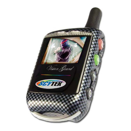
Page 8: True Color 2-Way Camera Ready Remote Transmitter Description
Button 3 Button 4 The VisionGuard 6000 True Color 2-way LCD remote transmitter, is offering increased range and confirmation of any activated features. Button 1 Arms the system. Button 1 also locks the doors when the system is in Valet Mode. -
Page 9: Adding/Replacing 2-Way Transmitters
In order to change the battery, first slide the battery door locking pin to the side. Carefully slide the battery cover downward until it is free. While replacing the battery make sure that the positive and negative terminals are positioned correctly, then carefully reassemble the transmitter case. VisionGuard 6000 - Page 5... -
Page 10: Camera Features
Camera Features Page 6 - VisionGuard 6000... - Page 11 VisionGuard 6000 - Page 7...
-
Page 12: System Operation
* During Disarming, if the system was triggered while away from the vehicle, the siren will chirp 3 times, the parking lights will flash 3 times, and the LED will flash to indicate triggered zone. See Tamper Alert for zone listing. Page 8 - VisionGuard 6000... -
Page 13: Tamper Alert
= shock sensor Silent Arming/Disarming The VisionGuard 6000 system can be programmed to operate the system without Arm and Disarm chirp indications. When programmed for full-time silent operation, the siren will sound only when the system is triggered. -
Page 14: Panic Mode
Optional Coded Emergency Override As an extra measure of security, the VisionGuard 6000 is equipped with an optional Coded Emergency Override feature. Once an Emergency Override Code is chosen and programmed during installation, the system can no longer be disarmed using the standard override procedure. -
Page 15: Automatic Rearming
· The siren will chirp twice to confirm the Valet Mode is off. 3. Turn off the ignition. While in Valet Mode the remote transmitters will continue to lock and unlock the doors, and operate the optional auxiliary functions. VisionGuard 6000 - Page 11... -
Page 16: Remote Start Features
Side lights will flash indicating that the Cold Start mode has been activated. To turn off Auto Cold Starting do one of the following: · Turn ignition On. · Arm and then Disarm the system · Alarm or Panic the system Page 12 - VisionGuard 6000... -
Page 17: Automatic Start Mode
· After the engine shuts down the doors will lock (if installed). 2. Pressing the Brake Pedal. 3. Opening the Hood. 4. Remote Start Time-Out (completion of the timed run cycle). 5. Immergency Brake Off. VisionGuard 6000 - Page 13... -
Page 18: Extended Features
Remote Transmitter, and remain on for 30 seconds or until the ignition is turned on. Auxiliary Function Outputs The VisionGuard 6000 system is equipped with 3 Auxiliary Channel Outputs allowing the convenience features of the system to be further expanded. These outputs can be programmed for pulsed, timed, or... -
Page 19: System Installation
6. Verify with the owner, the mounting locations for all visible components, including the LED and Override switch. Verify with the owner, the optional features of the VisionGuard 6000 and the features that must be programmed during installation. 8. Inspect and perform a function test of all vehicle systems before and after the installation. -
Page 20: Mounting The Control Unit
Suggested mounting locations include air conditioning ducts, dashboard braces, or center console supports. During proper operation, the shock sensor will detect impacts to the vehicle only and will not usually be triggered by slow rocking movements of the vehicle like those caused by wind. Page 16 - VisionGuard 6000... -
Page 21: System Wiring
Pin 10 RED WIRE: Module Power Input (+). Connect to a constant source of +12V. Pin 11 VIOLET WIRE: Positive Door Input (+). Connect to the door switch circuit wire that shows +12V VisionGuard 6000 - Page 17... -
Page 22: Plug-In Connectors
2-Pin White Connector: Located on the side of the main module. · Green WIRE - Parking Brake Input (-) For vehicles equipped with a turbo charged engine. Must be connected if using the Turbo Timer feature. · Blue WIRE - Not Used. Page 18 - VisionGuard 6000... -
Page 23: Jumper Settings
Parking Light Output. Selects the polarity (+/-) for the output of the on-board Parking Light relay. Left Pin + Center Pin = positive Right Pin + Center Pin = negative default setting shown VisionGuard 6000 - Page 19... -
Page 24: System Programming
Ignition Door Locking. Selects whether or not the system will automatically lock the doors 10 seconds after the ignition key is turned on. Override Code Set. Changes the Emergency Override Code for a higher level of security. Page 20 - VisionGuard 6000... -
Page 25: Branch Table
7. Door Lock Pulse Length. Selects between a 1, 3 or 0.1 seconds output for door locking and unlocking. Program to 3 seconds for vehicles equipped with vacuum door locking systems. VisionGuard 6000 - Page 21... - Page 26 Tach Monitor mode: monitors the vehicle’s tach wire (or a fuel injection wire) in real-time to determine engine status and adjust starter crank time automatically. Gas Engine. Sets the engine type for Gasoline. Page 22 - VisionGuard 6000...
- Page 27 Factory Rearm Mode - enables the output to operate as a Factory Rearm output. 28. Zoom Mode. Picture Zoom Mode- select zoom 1X, 2X, 4X 29. Picture Orientation. Select Normal or Inverted VisionGuard 6000 - Page 23...
-
Page 28: Wiring Diagrams
+12V Orange wire Yellow Wire (-) ANTIGRIND/ (-) GLOW PLUG (+) IGNITION Yellow Wire STARTER DEFEAT WIRE FROM (+) IGNITION Violet Wire VEHICLE (+) STARTER TO STARTER Blue/Yellow Wire IGNITION SWITCH (+) GLOW PLUG INPUT Page 24 - VisionGuard 6000... -
Page 29: Door Lock Diagrams
Follow the diagrams below for connecting basic door lock systems. For Two Stage door lock systems (separately unlocks driver and passenger doors) see following pages. Negative Trigger Positive Trigger Green Wire Blue Wire Reverse Polarity Vacuum Adding Actuators VisionGuard 6000 - Page 25... -
Page 30: Two Stage Door Lock Diagrams
Two Stage Door Lock Diagrams The VisionGuard 6000 is equipped with a dedicated Passenger Unlock output allowing Two Stage Door Lock operation. When connected as shown below, disarming the system will unlock only the driver’s door. Pressing the disarm button again will unlock all doors. - Page 31 Two Stage Door Lock Diagrams cont’d Two Stage Reverse Polarity Two Stage Adding Actuators VisionGuard 6000 - Page 27...
-
Page 32: Technical Information
This device complies with Part 15 of FCC Rules. Operation is subject to the following two conditions: 1) This device may not cause harmful interference. 2) This device must accept any interference received, including interference that may cause undesired operation Page 28 - VisionGuard 6000... -
Page 33: System Diagnostics
Starter doesn’t start and Side Lights flash: 3 Times - Engine RPM not detected Hood Trigger is active 4 Times - Brake Trigger is active 5 Times - Unit is in Valet (service) mode, and start is disabled. VisionGuard 6000 - Page 29... - Page 34 Page 30 - VisionGuard 6000...
- Page 35 VisionGuard 6000 - Page 31...
-
Page 36: Wiring Diagram
Horn Output (-)500mA Violet Starter Output Yellow Ignition 1 Output Orange Accessory Output Brown Ignition 2 Output +12V Battery Input #1 +12V Battery Input #2 ScyTek Electronics 11627 Cantara Street North Hollywood, CA 91605 © ScyTek Electronics 2005 VisionGuard 6000 r3 11/05...