Table of Contents
Advertisement
Quick Links
Advertisement
Table of Contents

Related Manuals for Garland Mealstream CTM3


Summary of Contents for Garland Mealstream CTM3
-
Page 2: Table Of Contents
TABLE OF CONTENTS Microwave safety precautions..........3 Safety code ................4 Product specifications ............. 5 Installation instructions............6 Main features ............... 7-8 Principal components: LHS............. 9 Principal components: RHS ..........10 Principal components: Top............ 11 Principal components: Back view.......... 12 Principal components: Door &... -
Page 3: Microwave Safety Precautions
MICROWAVE SAFETY PRECAUTIONS CAUTION WARNING TO SERVICE TECHNICIANS PRECAUTIONS TO BE OBSERVED BEFORE AND DURING SERVICING TO AVOID POSSIBLE EXPOSURE TO EXCESSIVE MICROWAVE ENERGY (a) Do not operate or allow the oven to be operated with the door open. (b) Make the following safety checks on all ovens to be serviced before activating the magnetron or other microwave source, and make repairs as necessary: 1) interlock operation. -
Page 4: Safety Code
SAFETY CODE This manual is designed to assist engineers who have been on a recognised product familiarisation and training course run by Garland. It has been prepared to offer technical guidance for the Mealstream range of Combination Microwave Ovens. Please remember that it is wiser not to attempt a service task if you are unsure of being able to complete it competently, quickly, and above all safely. -
Page 5: Product Specifications
PRODUCT SPECIFICATIONS Model Number: + Voltage + Frequency + Phases + Controls + Country Model No. CTM3 Voltage 208V 240V Frequency 50Hz 60Hz Phases Single Three Control Type Series 5 Country N.America Customer Variant N.America TH = Tim Hortons Power 208Volts 208V ac 60Hz 30Amp 2P &... -
Page 6: Installation Instructions
INSTALLATION INSTRUCTIONS Installation Instructions for Mealstream Combination Ovens Power Supply Requirements The Mealstream Series should be connected to a suitable electricity supply, which can cope with the switching-on surge that occurs with certain types of catering equipment, including microwaves. Because of this requirement, we strongly recommend that a separate, suitably rated supply is installed for the oven. -
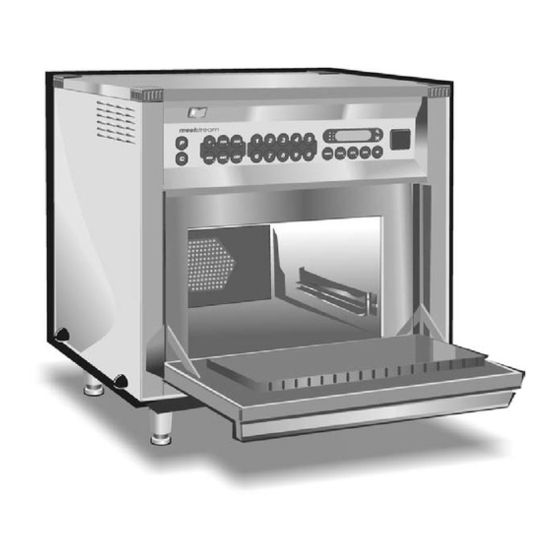
Page 7: Main Features
MAIN FEATURES On/Off SWITCH HOT AIR FAN This is used to turn the oven On or Off. Situated behind the baffle plate, and circulates the hot air through the baffle IT DOES NOT ISOLATE INTERNAL plate, over the heating element, and around WIRING FROM THE MAINS SUPPLY. -
Page 8: Main Features
MAIN FEATURES Electronic control panel Stage LED's Program & Time Display Convection Pad Power Pads Time / Preset Pads Temperature Set Pads Cancel / Callback Pad Program Pad Menukey™ Tim Hortons control panel MENU Preheat Cancel M Icon Cook Pads MenuKey™... -
Page 9: Principal Components: Lhs
PRINCIPAL COMPONENTS Left side Description 208V 240V Fuse holder 30Z0231 30Z0231 Fuse 10 amp 30Z0217 30Z0217 Fuse holder 30Z0231 30Z0231 Fuse 10 amp 30Z0217 30Z0217 Fuse holder 30Z0285 30Z0285 Fuse 1 amp 30Z0957 30Z0957 Fuse holder 30Z1178 30Z1178 Fuse 20 amp 30Z1177 30Z1177 Fuse holder... -
Page 10: Principal Components: Rhs
PRINCIPAL COMPONENTS Right side Description 208V 240V Door spring 40C1141 40C1141 Door spring Kit 10C0177 10C0177 Note A: Ovens before Door arm stop assembly 11C0279 11C0279 June 2003 Door arm assembly 11C0300 11C0300 Door hinge assembly ( RH ) 11C0166 11C0166 Note B: See page 17 for... -
Page 11: Principal Components: Top
PRINCIPAL COMPONENTS Top view Description 208V 240V Magnetron (Panasonic) 30Z1171 30Z1171 Resistor 470 R 30Z0283 30Z0283 Capacitor 0.88μf (2300V) 30Z0861 30Z0861 Capacitor 0.88μf (2500V) Kit 10C0172 10C0172 Transformer 30Z1230 30Z1230 Twin blower motor 30Z1145 30Z1145 25mm OD Flexible conduit 314402 314402 20mm OD Flexible conduit 314401... -
Page 12: Principal Components: Back View
PRINCIPAL COMPONENTS Back view Description 208V 240V Hot air motor assembly 10C0192 10C0192 Capacitor (motor start ) 6μF 30Z1148 30Z1148 Overheat Safety Thermostat 30Z1024 30Z1024 Hot Air motor Resistor Assy 11C0341 Twin Blower Resistor Assy 11C0477 Mealstream Ovens Pt. No. 32Z3403 Issue 16 Page 12... -
Page 13: Principal Components: Door & Cavity Roof
Bolt 1/4" 20 UNC 3/4" Hex 109050 109050 Cavity roof seal (short) 790052 790052 Door Handle 40C1020 40C1020 Door Assembly Garland 11C0336 11C0336 Door Assembly Tim Hortons 11C0380 11C0380 Door Assembly Unbranded 11C0418 11C0418 Flat Washer S/S M5 x 20... -
Page 14: Principal Components: External Parts & Accessories
PRINCIPAL COMPONENTS External Parts and accessories All models before All models Description February 2004 after February 2004 Side Panel Left Side 790002 40C1182 Side Panel Right Side 790003 40C1183 Top Panel 790005 40C1181 Foot 32Z1052 32Z1052 Wire Rack 40C1011 40C1011 Crumb Tray RBR290X02 RBR290X02... -
Page 15: Principal Components: Cavity Parts
Heater element 40C0949 40C0948 Heater element 790047 790047 cover plate Baffle 11C0311 11C0311 Dome Nut 80X7025 80X7025 Shelf Support (Garland) 40C0950 40C0950 Hot Air Impeller 10C0236 10C0236 Shelf Support 10C0174 10C0174 Tim Hortons Shelf support fixing bolt 80T7133 80T7133 Tim Hortons... -
Page 16: Principal Components: Tim Hortons Control Panels
TIM HORTONS CONTROL PANEL US/ English Description 208V 240V Control Panel Assy with Menukey 11C0332 11C0332 Logic Board 11C0331 11C0331 Relay Board 11C0316 11C0212 US/ English 1/4 Load Description 208V 240V Control Panel Assy with Menukey 11C0412 11C0412 Logic Board 11C0411 11C0411 Relay Board... -
Page 17: Principal Components ( Not Shown In Main Views )
PRINCIPAL COMPONENTS ( not shown in main views ) Right Hand Door Hinge Left Hand Door Hinge Assembly Assembly Stirrer motor assembly Description All models Door Hinge Assembly LH 11C0167 Door Hinge Assembly RH 11C0166 790027 Roller 40C0752 M5 Hex/hd s/s Screw 101825 M5 stainless steel Nut 80X7003... -
Page 18: Principal Components: Input Wiring Details
PRINCIPAL COMPONENTS Input wiring details Green/Yellow Black Green White Description All models Electrical Supply Terminal Block 31Z0149 Cable Gland 31Z0500 Gland Nut 31Z0499 Electrical Supply Cord 3 Core 30Z1162 Electrical Supply Plug 50Amp 31Z0298 (Canada) Hot Air Motor connections and Wiring 208V 60 Hz 240V 60 Hz Mealstream Ovens Pt. -
Page 19: Principal Components: Part No. Identification Charts
PRINCIPAL COMPONENTS: Part Number Identification Chart 1 Part No Description Page No 208V 240V Fuse holder 30Z0231 30Z0231 Fuse 10 amp 30Z0217 30Z0217 Fuse holder 30Z0231 30Z0231 Fuse 10 amp 30Z0217 30Z0217 Fuse holder 30Z0285 30Z0285 Fuse 1 amp 30Z0957 30Z0957 Fuse holder 30Z1178... - Page 20 Magnetron Thermal Trip 2571016 2571016 Cavity Overheat Thermostat 30Z1024 30Z1024 Door Handle 40C1020 40C1020 Cavity Vent Pipe 40C1013 40C1013 Electrical Supply Plug (50A Canada) 31Z0298 31Z0298 Shelf Support (Garland) 40C0950 40C0950 Mealstream Ovens Pt. No. 32Z3403 Issue 16 Page 20...
- Page 21 PRINCIPAL COMPONENTS: Part Number Identification Chart 3 Part No Description Page No 208V 240V Door Assembly Garland 11C0336 11C0336 Door Assembly Tim Hortons 11C0380 11C0380 Door Assembly Unbranded 11C0418 11C0418 Hot Air Motor Resistor Assy 11C0341 Diode assy with leads...
-
Page 22: Procedure For Microwave Leakage Test
Check for radiation leakage after servicing. Should the leakage be more than 4mW/cm² Inform Garland service centre immediately. After repairing or replacing any radiation safety device, keep a written record for future reference, as required by D.H.H.S. and Health and Welfare Canada regulation. - Page 23 • Readings must be below 4mW/cm². If a level greater that 4mW/cm² is observed, this should be reported to Garland Service Division immediately. • In any case, notes should be kept of the leakage that is observed. In terms of level and position on the oven.
-
Page 24: Procedure For Power Output Measurement
PROCEDURE FOR POWER OUTPUT MEASUREMENT The power output specification, 1425W on this model is established under IEC 705 standard method. This method is only workable in Laboratory controlled conditions. An approximate method is as follows: Tim Hortons Ovens To carry out this test the Icon Pads need to be switched to ENGINEERING MODE PROGRAMS See Appendix 1 Fill one beaker ( glass or plastic ) with one litre ( 1.78 pints ) of tap water ( at about 68ºF/ 20ºC ) and measure the water temperature. -
Page 25: Procedures For Principal Component Tests
PROCEDURES FOR PRINCIPAL COMPONENTS TEST (1) 1. Power Transformer Test You will need: A Digital Multi-meter (D.M.M.) A Megger or similar resistance meter using 500V d.c. WARNING: High voltages and large currents are present at the High Voltage Capacitor. It is very dangerous to work near this part when the oven is on. -
Page 26: Procedures For Principal Component Tests
PROCEDURES FOR PRINCIPAL COMPONENTS TEST (2) ( High Voltage Capacitor Test continued, ensure steps 1-4 on previous page have been completed) Between Terminals Pass if approximately 10 MΩ Between Terminals and Case Pass if open circuit 5. Using a Megger, test the insulation resistance between the terminals and the case. -
Page 27: Procedure For Door Interlock Adjustment And Test
PROCEDURE FOR DOOR INTERLOCK ADJUSTMENT AND TEST (1) The door on the Mealstream oven is monitored by three microswitches. These are used in the conventional “Primary, Secondary and Monitor” switch arrangement shown below. The switches operate as follows: Door Interlock Arrangement Switches shown in Door Closed position Secondary switch Primary switch... - Page 28 PROCEDURE FOR DOOR INTERLOCK ADJUSTMENT AND TEST (2) Please Note DO NOT attempt to carry out the following procedure unless you have the following tools and parts. Continuity Meter Spacer No. required Part No. Door Spacer Kit 40C1119 S10 Door Spacer 10mm Part No.
- Page 29 PROCEDURE FOR DOOR INTERLOCK ADJUSTMENT AND TEST (3) Step 2: Insert S10 10mm spacer into door. Interlock Order (See figure 1 below for inserting spacer SW1 (Monitor) CLOSED correctly). SW2 (Primary) OPEN SW3 (Secondary) OPEN Step 3: Remove S10 10mm spacer and insert S1 1mm Interlock Order spacer into the door and close the door.
-
Page 30: Procedure For Building And Fitting The Door
PROCEDURE FOR BUILDING AND FITTING MEALSTREAM DOOR (1) Parts required for door fitting Please Note DO NOT attempt to carry out the following procedure unless you have the following tools and parts. Item No. Description Part No. Quantity RHS door hinge assy 11C0166 M5 x 10mm 101820... - Page 31 PROCEDURE FOR BUILDING AND FITTING MEALSTREAM DOOR (2) 1. Visually check all parts to be used. Spacer 2. Fit right hand side (RHS) Hinge assy. to base assy. loosely fit in place with bottom bolts, 2 off M5 x 10mm, 2 off M5 flat washer, 2 off M5 shockproof washer.
- Page 32 PROCEDURE FOR BUILDING AND FITTING MEALSTREAM DOOR (3) Fit (RHS) and (LHS) door arm assemblies through slots in cavity and insert door arm pivot pins through door arms into door frame. Door arm pivot pin Ensure the door frame is fitted central by using the following method: Measure the distance between the side of the door and the edge of the pin location hole on each side...
- Page 33 PROCEDURE FOR BUILDING AND FITTING MEALSTREAM DOOR (4) Fit door shim plate Pt. No. 40C1084. ‘T’ Mark Position door choke to door frame assy making sure it is in the correct orientation (the top of door choke is marked with ‘T‘ on the underside).
- Page 34 PROCEDURE FOR BUILDING AND FITTING MEALSTREAM DOOR (5) 12. Fold the square piece oven insulation in half and place it in the recess in the oven door. Place the rectangular piece into the remainder of the door (foil facing out). Stage 2 Stage 1 Place the outer skin over the door frame...
-
Page 35: Procedure For Replacing Door Seal Assembly
PROCEDURE FOR REPLACING DOOR SEAL ASSEMBLY (1) Parts required for replacing carbon loaded door seals Please Note DO NOT attempt to carry out the following procedure unless you have the following tools and parts. Item Description Part Number Quantity Door seal set of 4 11C0292 CAF 30 ( Black ) 31Z0186... - Page 36 PROCEDURE FOR REPLACING DOOR SEAL ASSEMBLY (2) Figure 2 Figure 1 Figure 4 Figure 3 Figure 6 Figure 5 Figure 7 Figure 8 Please note. It is very important after completing this procedure, to do a Door interlock adjustment and test procedure. See pages 27-29.
-
Page 37: Procedure For Removing Shelf Runners & Element Cover
PROCEDURE FOR REMOVING SHELF RUNNERS AND ELEMENT COVER PLATE Please Note: DO NOT attempt to carry out the following procedure unless you have the following tools. Tools required for removing shelf runners and element cover plate. M6 nut runner M5 nut runner M5 stainless steel M6 x 12mm dome nut... -
Page 38: Procedure For Replacing Heater Element
PROCEDURE FOR REPLACING HEATER ELEMENT Please Note DO NOT attempt to carry out the following procedure unless you have the following part and tools. Parts required for replacing heater element. Item Description Part Number Quantity Heater Element 208 volt 40C0949 / 240 volt 40C0948 Mesh Washer 31Z5044 Tools required for replacing heater element. -
Page 39: Procedure For Replacing Hot Air Motor Assembly
PROCEDURE FOR REPLACING HOT AIR MOTOR ASSEMBLY Please Note DO NOT attempt to carry out the following procedure unless you have the following part and tools. Parts required for replacing hot air motor assembly. Item Description Part Number Quantity Hot Air Motor Assembly 11C0312 Tools required for replacing hot air motor assembly. -
Page 40: Procedure For Replacing Magnetron Assembly
PROCEDURE FOR REPLACING MAGNETRON ASSEMBLY (1) Parts required for replacing magnetron Please Note DO NOT attempt to carry out the following procedure unless you have the following tools and parts. Item Description Part Number Quantity Magnetron 30Z1171 Tools required for replacing magnetron Philips screw driver M5 nut runner WARNING... - Page 41 PROCEDURE FOR REPLACING MAGNETRON ASSEMBLY (2) Figure 1 - 6 Figure 2 Figure 1 Magnetron Temperature Screw connection Stat. block Figure 3 Figure 4 Temperature Stat. Screws 4 x Magnetron screw fixings Figure 5 Figure 6 Temperature Magnetron mount Wire mesh Stat.
-
Page 42: Procedure For Testing Membrane Panel Circuit
PROCEDURE FOR TESTING MEMBRANE PANEL CIRCUIT You will need: A Digital Multi-meter (D.M.M.) 1. The oven isolate from the electrical supply. 2. Remove the Logic Assembly from the Control Panel Housing. 3. Unplug the membrane “tail” from the Logic PCB Assembly. 4. -
Page 43: Procedure For Testing Membrane Panel Circuit
PROCEDURE FOR TESTING MEMBRANE PANEL CIRCUIT (2) Mealstream 501 US Tim Hortons & Unbranded Variant Note:PINS 1-4 Lower Layer & Pins 5-10 upper layer Mealstream 501 US Tim Hortons French (Canada) Note:PINS 1-4 Lower Layer & Pins 5-10 upper layer Mealstream Ovens Pt. -
Page 44: Circuit Diagrams
CIRCUIT DIAGRAM: ALL MODELS Mealstream Ovens Pt. No. 32Z3403 Issue 16 Page 44... -
Page 45: Error Codes And Diagnostics
ERROR CODES AND DIAGNOSTICS The Mealstream will identify some of the most common problems by flashing an error message code in the time display window. These are the error messages, and suggestions for repairing them. Door not fully shut. Close door fully. Possible electrical fault Door switch inoperative. -
Page 46: Appendix 1: Test Procedure For Tim Hortons
APPENDIX 1 Tim Hortons variants: Power Test and Microwave Leakage Test (Pages 22-24) Engineering Mode programs In order to carry out the Power Test and Microwave Leakage Test on Tim Hortons variant Ovens, the Icon Pad programs on the control panel need to be switched to Engineering Program Mode. -
Page 47: Appendix 2: Menukey® Download Procedure
APPENDIX 2: MenuKey™ DOWNLOAD PROCEDURE The MenuKey™ System automatically changes all the cooking programs on the numbered icon pads with the turn of a key. To change the menus on the oven: Ensure the power switch is off. Lift the MenuKey™ cover in the top panel of the oven and put the key in the keyhole Turn the key clockwise to the stop ( ¼... -
Page 48: Appendix 3: Temperature Sensor Resistance Data
APPENDIX 3: TEMPERATURE SENSOR RESISTANCE DATA Temperature Sensor Resistance Temp °F Temp °C Min. Rate Standard Max. Rate Rate k 11.490 13.060 14.810 2.803 3.161 3.434 1.741 0.950 1.000 1.050 0.3572 0.3865 0.4171 R(200)°C = 1 k ± 5% Note: These resistances will only be apparent in a stable cavity temperature as the sensor has a slow response time. -
Page 49: Appendix 4: Cleaning Procedure
APPENDIX 4: Cleaning procedure Mealstream 501 For the oven to operate at peak efficiency, the cavity, door and the air filters must be kept clean. A daily cleaning routine will ensure that you comply with the required hygiene standards and will help to maintain and prolong the efficiency of your oven. Follow the SAFETY INSTRUCTIONS at the beginning of this manual. -
Page 50: Appendix 5: Hot Air Motor Upgrade
APPENDIX 5: Hot Air Motor Upgrade Hot Air Motor Upgrade to High Speed Type: Models before February 2005 Cavity showing Impeller with threaded securing nut Rear view of oven showing Hot Air Motor ( Element cover plate removed ) Pre-February 2005 If the oven has an impeller secured with a Impeller with Threaded Nut it should be upgraded with... -
Page 51: Appendix 6: Recommended Spares List
APPENDIX 6: Recommended spares list Recommended spares list (to support 1– 3 ovens) Available as complete kit on part number 10C0244 (208V 60Hz) Item Part Quantity Description Number per kit 11M0417 HT DIODE PCB ASSY 11C0292 CTM3 DOOR SEAL SET 11C0319 STIRRER GLASS ASSY 11C0324... -
Page 52: Appendix 7: Door Stop & Adjustable Microswitch Bracket
APPENDIX 7: Door stop & Adjustable microswitch bracket All Oven models from May 2005 Description 208V 240V Door arm stop assembly 11C0480 11C0480 Adj. Microswitch support bracket 40C1233 40C1233 Mealstream Ovens Pt. No. 32Z3403 Issue 16 Page 52... -
Page 53: Appendix 8: Door Arm Guide
APPENDIX 8: Door arm guide Door arm guide upgrade Ovens manufactured before Serial No. 144460505, May 2005 Parts required: Pt. No. 40C1241 Door arm guide Brief description: It has been identified that in transit and under some operating conditions the door arm can lift and become jammed behind the lever on Microswitch SW1. -
Page 54: Manual Corrections And Modifications
Name Address Page number on which error occurs (if applicable) - Mealstream Garland Description of error Suggestion for improvement to manual Please return this form to:...