Advertisement
ModelNo.WESY3924.4
SedalNo.
WritetheseriaU n umber i n the
space
above for reference,
SeriaU Number DecaU(under seat)
As a manufacturer,
we are com-
mitted to providing
complete
customer
satisfaction,
if you
have questions,
or if a part is
damaged or missing,
PLEASE
CONTACT OUR CUSTOMER
SERVICE DEPARTMENT
DIRECTLY.
CALL TOLL-FREE:
1-877-992-5999
Mon.=Fd., 6 a.m.=6 p.m. MST
ON THE WEB:
www.weiderservice.com
Read aH precautions
and instruc-
tions in this manuaJ before using
this equipment.
Save this manuo
aJfor future reference.
www°weiderfitness°com
new products,
prizes,
fitness tips, and much more!
Advertisement
Table of Contents

Related Manuals for Weider MAX XP400


Summary of Contents for Weider MAX XP400
- Page 1 ModelNo.WESY3924.4 SedalNo. WritetheseriaU n umber i n the space above for reference, SeriaU Number DecaU(under seat) As a manufacturer, we are com- mitted to providing complete customer satisfaction, if you have questions, or if a part is damaged or missing, PLEASE CONTACT OUR CUSTOMER SERVICE DEPARTMENT...
-
Page 2: Warning Decal Placement
TABLE OF CONTENTS WARNING DECAL PLACEMENT ............. iMPORTANT PRECAUTIONS ..............BEFORE YOU BEGIN ..............ASSEMBLY ................ADJUSTMENTS ................CABLE DIAGRAM ................. EXERCISE GUiDELiNES ..............ORDERING REPLACEMENT PARTS ..........Back Cover LiMiTED WARRANTY .............. Back Cover Note: A PART iDENTiFiCATiON CHART and a PART LIST/EXPLODED DRAWING are attached in the center of this manual, Remove the PART iDENTiFiCATiON CHART and PART LIST/EXPLODED... - Page 3 iMPORTANT PRECAUTIONS , WARNING: To reduce the risk ofee,ous i njury, read t he fo,owing mportant precautions before using the resistance system. Read all instructions in this manual and all The resistance system is designed to sup- warnings on the resi stance system before port a maximum user weight...
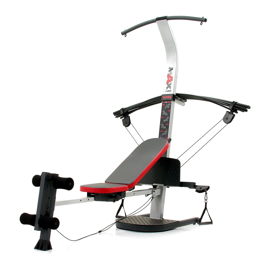
- Page 4 BEFORE YOU Bm=GmN manual, The model number is WESY3924,4, The serial Thank you for selecting the innovative MAX by number can be found on a decal attached to the resist° WELDER®XP400 resistance system, The resistance system offers a selection of stations designed to devel- anee system (see the front cover of this manual for the op every major muscle group of the body, Whether your location of the decal),...
- Page 5 • Tighten all parts as you assemble them, unless Make Things Easier for Yourself instructed to do otherwise, This manual is designed to ensure that the resist- As you assemble the resistance system, make ance system can be assembled successfully by sure all parts are oriented as shown in the draw- most peopb, However, it is important to realize ings,...
- Page 6 Attach a WheeU ( 31)totheoutside ofthe Base(1) withanMIOx 78mmBoUt (81),threeMIO Washers ( 75),andan MIONyUon Locknut ( 76). Do not overtightenthe Locknut;the Wheel mustbeableto turn easily. Attach the other Wheel (not shown} in the same manner. Orient the Cross Tube (11) as shown, with the weUded tubes at the bottom.
- Page 7 Attach the Lat Tower (4) to the Upright (3) with four MIO x 25mm Button Head Screws (87), and four MIO Lock Washers (68), Attach the Name Hate (89) to the Lat Tower (4) with two M4 x 16mm Screws (62), Attach two EyeboUts (34) to the Top Frame (10) with two M8 Washers (59) and two M8 NyUon Locknuts (65), Do not overtighten...
- Page 8 Attach two 8mm MetaUSpacers (91), a 60mm MetaU Spacer (39), and two Bearing WheeUs (46) to one end of the Seat Carriage (12) with an M8 x 104mm Button Head BoUt(60) and an M8 NyUon Locknut (65) as shown, Make sure that the parts second set of wheels are oriented...
- Page 9 12, Attach a PUastic Foot (53) to the Backrest Frame (15) with an M4 x 16mm Screw (62), Attach the two Guard Hates (17) to the inside of the Backrest Frame (15) with four M4 x 16mm Screws (62), 13, Orient the Backrest (14) as shown, Attach the Backrest to the Backrest Frame (15) with four 1/4"...
- Page 10 15, Locate the fubrum on the Lat Tower (4) (see the inset drawing), Slide the Tray (35) onto the rods on the fubrum, Make sure the Tray is oriented as shown in the drawing. Edges Set the Resistance Bars into the Tray (35) in the following order: the lO-pound Resistance Bar (67), the 20-pound Resistance Bar (36), an 80-pound Resistance Bar (95), the lO-pound Center...
- Page 11 19, Wrap the Long Cable (80) under a 90mm Pulley (28) as shown, Attach the Pulley and a Cable Trap (29) to the Upright (3) with an MIO x 120mm Button Head Bolt (40) and an MIO Nylon Locknut (76), Make sure the Cable Trap is oriented hold the Cable in the groove of the Pulley.
- Page 12 23, Locate the Leg Lever Cable (32), which has two ends that are the same Uengthand a third end that is Uonger, Route the Uongest end of the Leg Lever CabUe (32) through the hoUein the Front Leg (6), and attach it inside of the hoUein the Leg Lever (7) with an MIO x 5Omm BoUt(63) and an MlO NyUon Locknut (76),...
- Page 13 ADJUSTMENTS This section expUains how to adjust the resistance system, See the EXERCUSE GUUDEMNES on page 17 for important information about how to get the most benefit from your exercise program, AUso,see the accompany° ing exercise guide to see the correct form for each exercise, Make sure aH parts are properUy tightened each time the resistance system is used, RepUace worn parts immedi- ateUy,The resistance system can be cleaned with a damp cUothand a miUd,non-abrasNe detergent, Do not use soUvents, The resistance bars can be cleaned with a vinyUand rubber protectant, avaHaMe at an automotive or...
- Page 14 ATTACHING THE ACCESSORIES To attach a Handb (49) to a high pulley, first attach the high pulley to the resistance system (see ATTACHING 81---@ THE HUGHPULLEYS AND LEG LEVER on page 13), Then, attach the Handb to the Short CaMe (33) with a CaMe CHp (51), The Ankb Strap (not shown) can be attached to the Long Cabb (80) with CaMe CHps (51), Attach the Leg...
- Page 15 ADJUSTING THE BACKREST The Backrest (14) can be used in a bveU position or one of three inclined positions, To use the Backrest in a bveU position, secure the Seat Carriage (12) to the adjustment hob in the Bench Rail (5) next to the Front Leg (6) (see ADJUSTING THE SEAT on page 13), To use the Backrest (14) in an inclined position, secure the Seat Carriage (12) to one of the other...
-
Page 16: Cable Diagram
CABLE DIAGRAM The cable diagram shows the proper routing of the Long Cable (80), Use the diagram to make sure that Long Cable (80) the Cable has been assembled correctly, if the Cable has not been correctly routed, the resistance system wiii not function properly and damage may occur, The numbers show the correct route for the Cable,... -
Page 17: Exercise Guidelines
EXERCISE GUiDELiNES THE FOUR BASIC TYPES OF WORKOUTS PERSONALiZiNG YOUR EXERCISE PROGRAM Muscb Building Determining the exact length of time for each workout, as well as the number of repetitions or sets completed, To increase the size and strength of your muscles, is an individual matter, it is important to avoid overdo- push them close to their maximum capacity, Your mus- cles wiii continually adapt and grow as you progres-... - Page 18 Rest for a short period of time after each set. The slowly as you stretch and do not bounce, Ease into ideaU resting periods are: each stretch gradually and go only as far as you can Rest for three minutes after each set for a muscb without strain, Stretching at the end of each workout building workout.
- Page 19 MONDAY EXERCISE RESISTANCE SETS REPS Date: AEROBIC EXERCISE TUESDAY Date: EXERCISE RESISTANCE SETS REPS Date: AEROBIC EXERCISE Date: FRUDAY EXERCISE RESISTANCE SETS REPS Date: Make photocopies of this page for scheduling and recording your workouts,...
-
Page 20: Part Identification
PART iDENTiFiCATiON CHART See the drawings bebw to identify small parts used in assemMy, The number in parentheses beUow each draw- ing is the key number of the part, from the PART LUST on the reverse side of this page, Note: Some small parts may have been pre-attached. - Page 21 M10 x 65ram Button Head Screw (70) M10 x 66ram Carriage Bolt (83) M10 x 68mm Bolt (56) MIO x 72ram Bolt (64) M10 x 78ram Bolt (81) MIO x 91ram Bolt (90) M10 x 103ram Bolt (66) M8 x 104ram Button Head Bolt (60) M10 x 102ram Button Head Bolt (24) F\ ,I M8 x 114mm Axle (57)
- Page 22 PART LiST--Model No. WESY3924.4 R080 A Key No. Qty. Description Key No. Qty. Description Base 26mm Spacer Base Hate Plastic Foot Upright 25mm Square inner Cap Lat Tower Leg Lever Bumper Bench Rail MIO x 68mm Bolt M8 x 114mm Axle Front Leg 1/4"...
- Page 23 EXPLODED DRAWING--Model No. WESY3924.4 noso_A 59 65 .Y" 7_ 28 ,1 82 62 83...
-
Page 24: Ordering Replacement
ORDERING REPLACEMENT PARTS To order repUacement parts, see the front cover of this manual To heUpus assist you, phase be prepared to give the following information: the MODEL NUMBER of the product (WESY3924,4) the NAME of the product (MAX by WEUDER XP400 resistance system) the SERIAL NUMBER of the product (see the front cover of this manuaU) the KEY NUMBER and DESCRiPTiON of the part(s) (see the PART LUSTand EXPLODED DRAWING in the...