Table of Contents
Advertisement
www.nordictrack.com
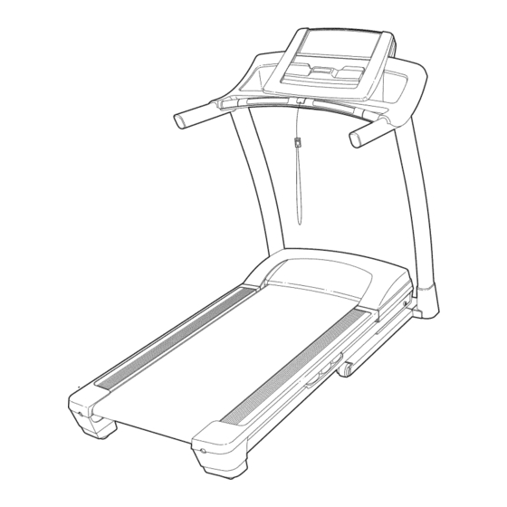
Model No. NTL08009.0
Serial No.
Write the serial number in the space
above for reference.
Serial Number
Decal
QUESTIONS?
If you have questions, or if parts are
damaged or missing, DO NOT CON-
TACT THE STORE; please contact
Customer Care.
iMPORTANT: Please register this
product (see the limited warranty
on the back cover of this manual)
before contacting Customer Care.
CALL TOLL-FREE:
1-888-825-2588
Mon.-Fri.
6 a.m.-6
p.m. MT
Sat. 8 a.m.-4
p.m. MT
ON THE WEB:
www.nordictrackservice.com
A
AL
Advertisement
Table of Contents

Related Manuals for NordicTrack A2550 PRO NTL08009.0


Summary of Contents for NordicTrack A2550 PRO NTL08009.0
- Page 1 Model No. NTL08009.0 Serial No. Write the serial number in the space above for reference. Serial Number Decal QUESTIONS? If you have questions, or if parts are damaged or missing, DO NOT CON- TACT THE STORE; please contact Customer Care.
- Page 2 • Keep clothing, KEEP HANDS ANDFEETAWAY • Neve_ try to adiust or llx the bell while FROM THISAREAWHILE THE ff is moving. TREADMILL I S INOPERATION. athletLc shoes while .Always wear operating t_eadmfll. NordicTrack is a registered trademark of ICON IP, Inc.
- Page 3 iMPORTANT PRECAUTIONS...
- Page 5 BEFORE YOU BEGIN Thank you for selecting the revolutionary NordicTrack ® ing this manual, please see the front cover of this man- A2550 PRO treadmill. The A2550 PRO treadmill offers ual. To help us assist you, please note the product an impressive selection of features designed to make model number and serial number before contacting us.
- Page 6 ASSEMBLY Assembly requires two persons. Set the treadmill in a cleared area and remove all packing materials. Do not dispose of the packing materials until assembly is completed. Note: The underside of the treadmill walking belt is coated with high-performance lubricant.
- Page 7 Make sure that the power cord is unplugged. Hole With the help of a second person, carefully tip the treadmill onto its left side. Partially fold the Frame (55) so that the treadmill is more stable; do not fully fold the Frame yet. Locate the Upright Wire (85), which is bundled at the front of the Base (94).
- Page 8 Identify the Right Upright Spacer (91), which is marked with a "Right" sticker. See the inset drawing. Orient the Right Upright Spacer (91) with the two curved corners posi- tioned as shown. Insert the Upright Wire (85) through the Right Upright Spacer (91) as shown.
- Page 9 Holda BoltSpacer ( 88)inside thelowerendof theRightUpright ( 83).Insert a 3/8"x 5 1/2" PatchBolt(7)witha 3/8"StarWasher ( 11)into theRightUpright a ndtheBoltSpacer. R epeat this step with a second Bolt Spacer (88), 3/8" × 5 1/2" Patch Bolt (7), and 3/8" Star Washer (11).
- Page 10 Attach the Base Cover (84) to the Base (94) with four #8 x 1/2" Screws (1). Be careful not to overtighten the Screws. With the help of a second person, tip the tread- mill so that the Base (94) is flat on the floor. Identify the Left Upright Cover (87).
- Page 11 Slide the Right Upright Cover (86) onto the Right Upright (83). Hold the Right Handrail (79) near the Right Upright (83). Insert the Upright Wire (85) through the Right Handrail as shown. Attach the Right Handrail (79) to the Right Upright (83) with a 5/16"...
- Page 12 11. Set the console assembly on the Left and Right Console Handrails (78, 79). Be careful not to pinch any Assembly wires. Insert the excess Upright Wire (85) into the Right Handrail. Attach the console assembly to the Handrails (78, 79) with four 5/16" x 1 1/2" Patch Bolts (4), four 5/16"...
- Page 13 13. Turn on the power (see page 16). See step 4 on page 17 and lower the incline to the lowest posi- tion. Remove the key from the console, switch the reset/off circuit breaker to the "off" position, and unplug the power cord. Raise the Frame (55) to the position shown.
- Page 14 Outlet Box the right). To purchase a surge suppressor, /ll _J I Adapter your local NordicTrack dealer or call the telephone number on the front cover of this manual and order part number 146148, or see your local electronics store.
- Page 15 CONSOLE DIAGRAM [Intermix _IH$Illl 2.81 _--zzzzssz START STOP FEATURES OF THE CONSOLE You can even listen to your favorite workout music or audio books with the console's stereo sound system. The treadmill console offers an impressive array of features designed to make your workouts more effec- To turn on the power, see page 16.
- Page 16 HOW TO TURN ON THE POWER HOW TO USE THE MANUAL MODE iMPORTANT: if the treadmill has been exposed to insert the key into the console. cold temperatures, allow it to warm to room tem- See HOW TO TURN ON THE POWER at the left. perature before turning on the power, if you do not...
- Page 17 Change the incline of the treadmill as desired. Measure your heart rate if desired. To change the incline of the treadmill, press the Before using Incline increase or decrease button, or one of the 1 the handgrip Step Incline buttons numbered 0 to 10. Each time pulse sensor, remove the you press one of the buttons, the incline will gradu-...
- Page 18 HOW TO USE A PRESET WORKOUT is programmed for the next segment, Current Segment Insert the key into the console. the speed and/or incline setting will flash in the displays |||||| See HOW TO TURN ON THE POWER on page 16. for a few seconds Select a preset workout.
- Page 19 HOW TO USE THE IFIT TRAINING MODE The console features a display demo mode, designed to be used if the treadmill is displayed in a store. While the demo mode is turned on, the console will function The console features the revolutionary iFit Live mod- ule.
- Page 20 HOW TO FOLD AND MOVE THE TREADMILL HOW TO FOLD THE TREADMILL FOR STORAGE Before folding the treadmill, adjust the incline to the lowest position, if you do not do this, you may damage the treadmill when you fold it. Remove the key and unplug the power cord.
- Page 21 HOW TO LOWER THE TREADMILL FOR USE 1. Hold the upper end of the treadmill with your left hand. Pull the latch knob to the right and hold it. It may be nec- essary to push the frame forward as you pull the knob to the right.
- Page 22 TROUBLESHOOTING Most treadmill problems can be solved by following the simple steps below. Find the symptom that applies, and follow the steps listed, if further assistance is needed, see the front cover of this manual. PROBLEM: The power does not turn on SOLUTION: Make sure that the power cord is plugged into a surge suppressor, and that the surge suppressor is plugged into a properly grounded outlet (see page 14).
- Page 23 Remove the four #8 x 3/4" Screws (14) and care- fully remove the Motor Hood (61). Locate the Reed Switch (44) and the Magnet (43) on the left side of the Pulley (42). Turn the Pulley until the Magnet is aligned with the Reed Switch. Make sure that the gap between the Magnet and 1/8 in.
- Page 24 PROBLEM: The walking belt is off-center or slips when walked on SOLUTION: a. If the walking belt is off-center, first remove the key and UNPLUG THE POWER CORD. If the walking belt has shifted to the left, use the hex key to turn the left idler roller bolt clockwise 1/2 of a turn;...
- Page 25 EXERCISE GUiDELiNES Burning Fat--To burn fat effectively, you must exer- cise at a low intensity level for a sustained period of time, During the first few minutes of exercise, your body uses carbohydrate calories for energy. Only after the first few minutes of exercise does your body begin to use stored fat calories for energy, If your goal is to burn fat, adjust the intensity of your exercise until your heart rate is near the lowest number in your training...
- Page 26 PART LIST--Model No. NTL08009.0 R0909A To locate the parts listed below, see the EXPLODED DRAWING near the end of this manual. Key No. Qty. Description Key No. Qty. Description #8 x 1/2" Screw Storage Latch #8 x 1" Tek Screw Latch Knob 3/8"...
- Page 27 Key No. Qty. Description Key No. Qty. Description Left Accessory Tray Site Warning Decal Console Base Wire Tie Clamp WiFi Module Housing 6" Blue Wire, M/F Right Accessory Tray 4" Red Wire, M/F Access Door 14" Black Wire, M/F Pulse Bar 8"...
- Page 28 r"" 18_+__ 4 23 -_ ...4 r" 55 18_, ¢0 r..,o r..,o >...
- Page 29 EXPLODED DRAWING B--Model No. NTL08009.0 RogogA --75 --109...
- Page 30 EXPLODED DRAWING CmModel No. NTL08009.0 ROgOgA...
- Page 31 EXPLODED DRAWING D--Model No. NTL08009.0 RoeoeA =103...
- Page 32 ORDERING REPLACEMENT PARTS To order replacement parts, please see the front cover of this manual. To help us assist you, be prepared to pro- vide the following information when contacting us: o the model number and serial number of the product (see the front cover of this manual) o the name of the product (see the front cover of this manual) o the key number and description of the replacement part(s) (see the PART LIST and the EXPLODED DRAWING near the end of this manual)