
Related Manuals for Salus RT500RF


Summary of Contents for Salus RT500RF
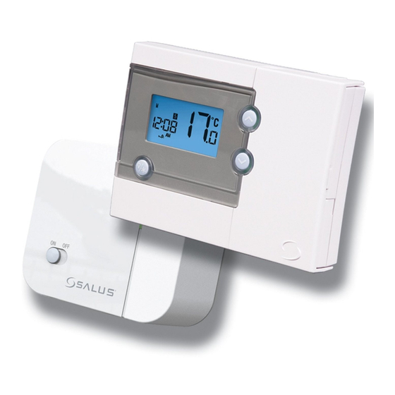
- Page 1 Salus RT500RF Manual:89 9/7/10 10:10 Page 1 Programmable Room Thermostat With RF Instruction Manual Model No RT500RF...
- Page 2 Page 2 RT500RF Warranty Salus Controls warrants that this product will be free from any defect in materials or workmanship, and shall perform in accordance with its specification, for a period of two years from the date of purchase. Salus Controls sole liability for breach of this warranty will be (at its option) to repair or replace the defective product.
-
Page 3: Product Compliance
• EC Marking directive 93/68/EEC SAFETY INFORMATION These instructions are applicable to the Salus Controls model stated on the front cover of this manual only, and must not be used with any other make or model. These instructions are intended to apply in the United Kingdom only, and should be followed along with any other statutory obligations. - Page 4 The RT500RF from Salus Controls is a stylish and accurate 5/2 or 7 day programmable electronic thermostat with a large, easy to read Liquid Crystal Display (LCD). This programmable thermostat has been specifically designed to be used for both Volt Free and AC heating applications.
-
Page 5: Installation
Control Centre. The back plate can be mounted directly to the wall surface. The ideal position to locate the RT500RF Control Centre is about 1.5m above floor level. It should be mounted in a location where the thermostat is accessible, reasonably lit and free from extremes of temperature and draughts. - Page 6 10:10 Page 6 The RT500RF Receiver should be mounted in a suitable location that is both accessible for the connection of mains and control wiring, and allows good reception of the RF signal. The Receiver needs a 230V AC mains supply to operate, and this should be fused appropriately (13A max.).
-
Page 7: Receiver Wiring Terminals
Salus RT500RF Manual:89 9/7/10 10:10 Page 7 RECEIVER WIRING TERMINALS Terminal Identifier Description Normally Open [N/O] Linked Live feed (230V AC heating applications only) Live feed (230V AC) Neutral TYPICAL WIRING INSTALLATIONS BOILER RECEIVER a.230V AC Installation N/O COM L N... - Page 8 Salus RT500RF Manual:89 9/7/10 10:10 Page 8 b. 24V Installation BOILER RECEIVER N/O COM L N MAINS FEED Thermostat loop (Remove link) Live Feed Notes: • Receiver unit should have a permanent 230V AC main supply • Confirm that the Boiler has an external thermostat loop and is NOT configured for 230V switching •...
- Page 9 Salus RT500RF Manual:89 9/7/10 10:10 Page 9 CONTROL CENTRE JUMPER SETTINGS Changes to the jumper settings should only be made by the Engineer carrying out the installation or other qualified person. The installer should select the jumper positions required if changes need to be made to the factory default settings.
-
Page 10: Rf Address Code Setting
Salus RT500RF Manual:89 9/7/10 10:10 Page 10 RF ADDRESS CODE SETTING If there is another unit being used nearby, e.g. in the next house or as part of a multiple installation, your Receiver may be fault triggered by the other Control Unit. - Page 11 Salus RT500RF Manual:89 9/7/10 10:10 Page 11 To adjust the RF address code of the Control Centre, remove one or more of the jumper caps located on the back of the unit (labelled 1,2,3,4 and 5, and shown in the picture below) so that the jumper settings match the settings...
-
Page 12: Testing The Rf Transmission
Salus RT500RF Manual:89 9/7/10 10:10 Page 12 TESTING THE RF TRANSMISSION It is important to site both the Receiver and Control Centre in locations where the RF signal cannot be interrupted. The receiving range between Control Centre and Receiver is approximately 30 metres indoors, however many factors can affect the RF transmission and shorten the operating distance, e.g. - Page 13 - once you are happy with the operation of one unit you can install the next. Once all the RT500RF units have been installed, if one unit then seems to function abnormally, try changing the RF address code of that unit’s Control Centre and its corresponding Receiver, making...
-
Page 14: After Installation
• The programme number is updated to indicate the running program If the Reset Button is pressed, the RT500RF will behave in the same way as described above, except that any previously saved user settings stored in the internal memory will be deleted and overwritten with the default settings, and all programmable thermostat control settings will be returned to default values. -
Page 15: User Interface And Controls
9/7/10 10:10 Page 15 USER INTERFACE AND CONTROLS The status and operation of the RT500RF is clearly shown on the large backlit Liquid Crystal Display (LCD). This display allows the user to see at a glance the current status of the heating system, the current time and day of the week, as well as a clear indication of the current room temperature. -
Page 16: Setting The Time
Press the SET key to confirm the new time and day settings. This will store the changes and return the RT500RF to Normal mode. The RT500RF Control Centre will also return to Normal mode (and save the clock settings) if no keys are pressed for more than 15 seconds. -
Page 17: Programming
Weekdays or Weekends. To review or change a programme, press the SET key when the RT500RF is in Normal mode. This will change the unit status to Programme Setting mode. - Page 18 Press the UP or DOWN key to select the programme set for either Weekday or Weekend to be reviewed or adjusted. Pressing the SET key at any time when in programming mode will return the RT500RF into Normal mode. Press the SELECT key to confirm the Weekday or Weekend selection. Once this is set, the ‘Hour’...
-
Page 19: Day Mode
35 separate programme settings. To review or change a programme, press the SET key when the RT500RF is in Normal mode. This will change the unit status to Programme Setting mode. - Page 20 – just repeat the steps shown above, after entering programming mode and selecting the day you want to programme. Regardless of which programming mode the RT500RF is set for (5/2 or 7 day), not pressing any keys for 15 seconds will automatically save any programming changes and exit to Normal mode.
-
Page 21: Frost Protection
FROST PROTECTION To enable the Frost Protection mode, press and hold the BACKLIGHT / FROST button for three seconds with the RT500RF in Normal mode. Once Frost Protection is enabled, the set point temperature is automatically set to 5°C to provide protection from the risk of freezing. -
Page 22: Temporary Override
• In Normal mode: press and hold either the UP or DOWN key to display the set point temperature. After two seconds, the RT500RF will enter Temporary Override mode and allow increase or decrease of the set point temperature. If the key is released within two seconds then you will only be able to review the set point temperature. - Page 23 Salus RT500RF Manual:89 9/7/10 10:10 Page 23 Once in Temporary Override mode, the clock and day are displayed, along with the SET indicator; all other indicators are cleared from the display. The set point temperature will flash to indicate that it can be changed: Pressing the UP or DOWN key will increase or decrease the set point temperature in 0.5 °C steps - the set point temperature can be adjusted...
-
Page 24: Reset Button
By pressing both the UP and DOWN keys together, the RT500RF will enter SLEEP mode. In this mode, all the RT500RF functions will be paused to save battery power, with the exception of the clock which will continue to run in the background. -
Page 25: Maintenance
• The RT500RF Receiver is switched on. • If the RT500RF is still not functioning correctly, press the Reset Button. WARRANTY Salus Controls warrants that this product will be free from any defect in materials or workmanship, and shall perform in accordance with its specification, for a period of two years from the date of purchase. -
Page 26: Product Specification
Salus RT500RF Manual:89 9/7/10 10:10 Page 26 PRODUCT SPECIFICATION Model: RT500RF Type: Electronic programmable thermostat, designed for Volt Free and AC heating applications. Frequency 868 MHz Programming Programming Modes: User selectable for 5/2 or 7 day option Number of Programmes: Five (5) user programmes plus factory default programme. - Page 27 Salus RT500RF Manual:89 9/7/10 10:10 Page 27 Clock Accuracy: ± 1 minute per month Display: 12 hour Frost Protection Setting: 5 ºC Setpoint Temperature Range: 5 ºC to 35 ºC Measured Air Temperature Range: 5 ºC to 45 ºC (Displayed on LCD)
- Page 28 Salus RT500RF Manual:89 9/7/10 10:10 Page 28 salus-tech. Email: sales@salus-tech.com Tel: 01226 323961 Sales Email: tech@salus-tech.com Tel: 01226 323961 Technical Salus Controls plc, Salus House, Dodworth Business Park South, Whinby Road, Dodworth, Barnsley S75 3SP...