Table of Contents
Advertisement
Sales +44 (0) 8700 766900
Technical +44 (0) 8700 766902
Salus Controls plc
Enterprise Park, Bala
Gwynedd, LL23 7NL
Regional offices, England & Scotland.
Web: www.salus-tech.com
Email: sales@salus-tech.com
Maintaining a policy of continual product
development Salus Controls plc. reserve the right to
change specification, design and materials of
products listed in this brochure without prior notice.
Manual Issue No. IM-RT500RF-002
In st ru ct io n M a nu al
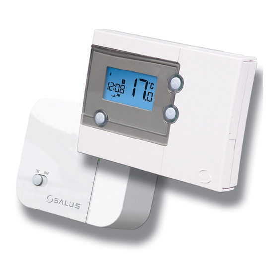
Programmable
THERMOSTAT
for Model No. RT500RF
Thank you for purchasing this Salus product
- if installing for someone else, please ensure that
the instructions are handed to the householder.
Warning - Please read this manual prior to
installation or use.
Shock Hazard
This unit must be installed by a competent person,
in accordance with BS 7671 (the IEE Wiring
Regulations), or other relevant national regulations
and codes of good practice.
Always isolate the AC Mains supply before
installing this unit.
Advertisement
Table of Contents

Related Manuals for Salus RT500RF


Summary of Contents for Salus RT500RF
- Page 1 Regulations), or other relevant national regulations and codes of good practice. Maintaining a policy of continual product development Salus Controls plc. reserve the right to Always isolate the AC Mains supply before change specification, design and materials of installing this unit.
-
Page 2: Switches/Jumpers
WIRING DIAGRAM PRIOR TO INSTALLING PLEASE READ THE Wiring the Receiver for the RT500RF INSTALLATION GUIDE FOR 230V APPLICATION 1) Remember to Isolate AC mains supply, note this INTRODUCTION must be 230V AC and fused at 13 amps max. The unit is default 230V, if volt f This thermostat can replace most common residential 2) Select a suitable indoor location free from water and required you must remove link &... -
Page 3: Wiring Diagram
WIRING DIAGRAM WIRING INTO THE EXTERNAL THERMOSTAT for the RT500RF RF Address Code Setting LOOP OF A BOILER FOR 230V APPLICATION (Remove Link on Receiver & AC mains supply, note this If there is another user nearby, e.g. i External Thermostat Link on Boiler!!!) d fused at 13 amps max. -
Page 4: Rf Address Code Setting
EXTERNAL THERMOSTAT TESTING THE RF TRANSMISSION Following table is the setting of the RF Address Code Setting (Remove Link on Receiver & It is important to site the Receiver and Control Centre in thermostat after reset or Power on: If there is another user nearby, e.g. in the next house, your nk on Boiler!!!) locations where the RF signal cannot be interrupted. -
Page 5: User Guide
User Guide G THE RF TRANSMISSION Following table is the setting of the tant to site the Receiver and Control Centre in thermostat after reset or Power on: where the RF signal cannot be interrupted. The Function Function Status after Reset or Power on ange between Control Centre and Receiver is Increase Setpoint Temperature en area. -
Page 6: Clock Setting Mode
uide Default Programme • Release SET and SELECT, press to increase or decrease the "hour" respectively. Function Program Weekday (M to F) Weekend (SA to SU) • Press and release SELECT, press increase or decrease the "minute" respectively. Increase Setpoint Temperature Time: 6:00am Time: 6:00am •... - Page 7 7 days program selected SELECT, press to increase • Press our" respectively. select the program • 5 different sets of Time and Setpoint set for Weekday / SELECT, press temperature can be set for each Day of Week. e the "minute" respectively. Weekend to be Total 35 settings.
-
Page 8: Frost Protection
Frost Protection: 5-2 or 7 days program • Clock, Day-of-Week, and "SE All other indicators are clear • Press and hold BL/FROST in Normal mode for 3 • The PROG indicator is displayed accordingly to The Setpoint temperature is flas seconds to activate the Frost Protection. -
Page 9: Lcd Backlight
LCD Backlight: • Clock, Day-of-Week, and "SET" are displayed. Reviewing Setpoint Temperature: All other indicators are cleared. L/FROST in Normal mode for 3 • LCD backlight is activated when • Press to review the Setpoint The Setpoint temperature is flashing to indicate that te the Frost Protection. -
Page 10: Lcd Backlight
LCD Backlight: tpoint Temperature: Sleep Mode: • LCD backlight is activated when BL/FROST or • Press and hold in Normal mode for 3 eview the Setpoint seconds simultaneously to enter the Sleep mode. any key is pressed. The backlight will automatically turn off in 5 seconds after all keys •...