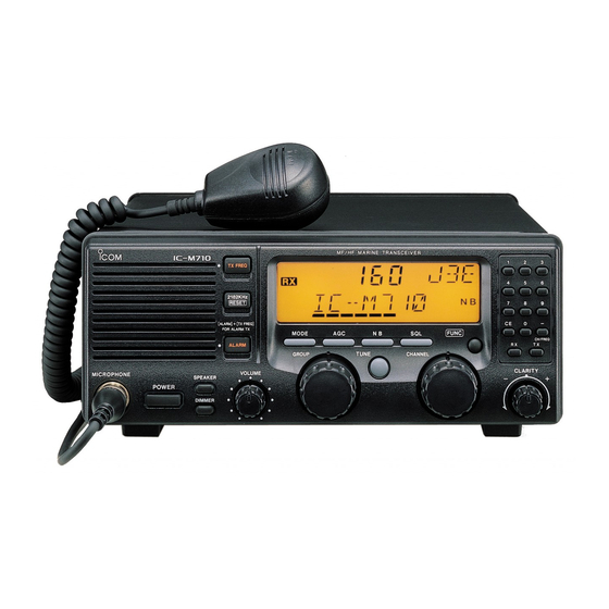
Icom IC-M710 Instruction Manual
Hf marine transceiver
Hide thumbs
Also See for IC-M710:
- Service manual (72 pages) ,
- Instruction manual (28 pages) ,
- Instruction manual (28 pages)
Table of Contents
Advertisement
Quick Links
Advertisement
Table of Contents

Related Manuals for Icom IC-M710


Summary of Contents for Icom IC-M710
- Page 1 INSTRUCTION MANUAL HF MARINE TRANSCEIVER iM710...
-
Page 2: Important
Icom, Icom Inc. and the Icom logo are registered trademarks of Icom Incorporated (Japan) in Japan, the United States, the United King- dom, Germany, France, Spain, Russia and/or other countries. -
Page 3: Table Of Contents
■ Antenna ·····························································20 D Using the channel selector ······························8 D MN-100/MN-100L ANTENNA MATCHERS 20 D Using the keypad ············································8 D AT-130 AUTOMATIC ANTENNA TUNER·····20 D Non-Icom tuner ·············································20 4 RECEIVE AND TRANSMIT ·····························9–11 ■ Mounting ···························································21 ■ Basic voice receive and transmit ·························9 D Mounting location ··········································21 ■... -
Page 4: Operating Rules And Guidelines
OPERATING RULES AND GUIDELINES ❑ CALL PROCEDURES ❑ LOGS Calls must be properly identified and time limits must q All distress, emergency and safety calls must be re- be respected. corded in complete detail. Log data activity is usu- ally recorded in 24 hour time. Universal Time (UTC) q Give your call sign each time you call another ves- is frequently used. -
Page 5: Panel Description
PANEL DESCRIPTION ■ Front panel This function is not installed in the IC-M710. RADIO TELEPHONE iM 710 TX FREQ 2182KHz RESET [ALARM] [TX FREQ] – FOR ALARM TX MODE FUNC CH/F/REQ TUNE GROUP CHANNEL CLARITY VOLUME MICROPHONE SPEAKER POWER DIMMER u ANTENNA TUNE SWITCH [TUNE] (p. - Page 6 PANEL DESCRIPTION ■ Front panel (Continued) This function is not installed in the IC-M710. RADIO TELEPHONE iM 710 TX FREQ 2182KHz RESET [ALARM] [TX FREQ] – FOR ALARM TX MODE FUNC CH/F/REQ TUNE GROUP CHANNEL CLARITY VOLUME MICROPHONE SPEAKER POWER...
- Page 7 PANEL DESCRIPTION !2 SQUELCH SWITCH [SQL] (p. 10) !5 MODE SWITCH [MODE] ➥ Activates the voice squelch function to reject Temporarily selects an operating mode. Available undesired background noise while no signal is modes differ with the transceiver version. being received. •...
-
Page 8: Display
NOISE BLANKER INDICATOR (p. 10) Flashes while the connected antenna tuner, such Appears when the [NB] switch is turned ON. as Icom’s AT-130, is being tuned. !0 AGC OFF INDICATOR (p. 10) • Tuning starts when transmitting on a new frequency or Appears when the [AGC] switch is pushed to indi- pushing the [TUNE] switch. -
Page 9: Selecting A Channel/Frequency
SELECTING A CHANNEL/FREQUENCY Selecting a channel ■ The transceiver has 160 user channels and ITU NOTE: When Channel 0 and/or 2182 kHz is se- channels. However, the number of user channels lected with the [2182KHz] switch, channel se- can be optionally restricted and ITU channels are lection is NOT possible. -
Page 10: D Using The Keypad
SELECTING A CHANNEL/FREQUENCY [EXAMPLE]: Selecting channel 153. D Using the keypad Direct channel selection via the keypad is available for quick channel selection. D U P q Be sure no “►” indicator appears on the display. • If appears, push [CE] and then it will disappear. w Enter the desired channel number via the keypad. -
Page 11: Selecting A Frequency
SELECTING A CHANNEL/FREQUENCY ■ Selecting a frequency NOTE: The selected frequency is used for tempo- The transceiver has 0.5 to 30.0 MHz general cover- rary receiving (transmitting is not available). This age receive capability, with 100 Hz resolution. The frequency is cleared once the channel is changed. receive frequency can be changed instantly, inde- If you want to program a frequency refer to p. -
Page 12: Receive And Transmit
RECEIVE AND TRANSMIT ■ Basic voice receive and transmit q Check the following in advance: w Select the desired channel to be received with the ➥ The microphone is connected. [GROUP] and [CHANNEL] selectors. ➥ The [SPEAKER] switch is turned OFF. •... -
Page 13: Functions For Receive
RECEIVE AND TRANSMIT ■ Functions for receive D Squelch function Push [SQL] to toggle the function ON or OFF. The squelch function detects signals with voice com- • ponents and squelches (mutes) unwanted signals, such as unmodulated beat signals. This provides D U P quiet standby. -
Page 14: Cw Operation (Depends On Versions)
• pin 3 justed in the set mode (pgs. 14 and 15). Some transceivers may operate 1.7 kHz higher • Ground ACC(1) socket than the IC-M710’s J2B mode, even when the FSK terminal unit same displayed frequencies are in use. -
Page 15: User Channel Programming
USER CHANNEL PROGRAMMING ■ Programming a frequency NOTE: ITU simplex channels can be programmed The IC-M710 has up to 160 user-programmable as well as user channels. However, transmit fre- channels each with channel name capability of up to quencies cannnot be programmed (not necessary 7 alphanumeric characters. -
Page 16: Set Mode
FSK channels appear (SITOR operation). (2) Connected antenna tuner The transceiver has several tuner control systems AT-130 for use with an optional Icom antenna tuner. Select (default) the condition depending on the connected antenna tuner. AT-120 Note that internal switch selection may be required when using a non-Icom tuner (p. - Page 17 SET MODE (4) Scan type selection Channel scan This item selects one of the following scan functions. Scan is canceled when Channel scan and channel resume scan search 5 transmitting. (default) channels around a user selected channel or search all ITU channels in the band when an ITU channel is Channel resume scan selected.
- Page 18 When connecting an external controller, such as a NMEA ID: 1 personal computer, 2-digit ID codes are required (default) to access the transceiver. The IC-M710 adopts the NMEA0183 format, and uses a “proprietary sentence” for remote control. NMEA ID: 99...
-
Page 19: Connections And Installation
CONNECTIONS AND INSTALLATION ■ Connections on the rear panel External speaker Optional AT-130 12 V battery q ANTENNA CONNECTOR (p. 20) u TUNER RECEPTACLE Connects a 50 ø HF band antenna with a 50 ø Connects a control cable to an optional AT-130 matched coaxial cable and a PL-259 plug. -
Page 20: Connector Information
CONNECTIONS AND INSTALLATION ■ Connector information ACC(1) SPECIFICATIONS PIN PIN NAME DESCRIPTION CW and FSK keying input. Input level: Less than 0.6 V for transmit. Connects to ground. Connected in parallel with ACC(2) pin 2. Input/output pin. Ground level: –0.5 to 0.8 V SEND Goes to ground when transmitting. - Page 21 CONNECTIONS AND INSTALLATION PIN PIN NAME DESCRIPTION SPECIFICATIONS REMOTE Modulation input from an external Input impedance: 600 ø MOD+ terminal unit. Input level: Approx. 100 mV rms MOD– Coaxial ground for MOD+. AF detector output for an external Output impedance: 600 ø terminal unit.
-
Page 22: Ground Connection
2 ground points may cause electrolysis. Undesirable ground points CAUTION: The IC-M710 has a negative ground. (these points may cause electrolysis) NEVER connect the IC-M710 to a “positive ground • Engine block ship,” otherwise the transceiver will not function. • Keel bolt... -
Page 23: Antenna
*For the AT-130, the [GND] terminal can be used inside of the [E] terminal. D Non-Icom tuner Some non-Icom tuners may be used with the IC- M710. Please consult your dealer or marina if you wish to use one. The following internal settings may be required for connection. -
Page 24: Mounting
CONNECTIONS AND INSTALLATION ■ Mounting RWARNING: NEVER D Mounting location mount the transceiver Select a location that provides easy access to the overhead. The weight of the transceiver is approx- front panel for navigation safety, has good ventilation imately 7.8 kg (17.4 lb), but its apparent weight will and is not subject to sea spray. -
Page 25: Installing The Internal Options
Front sealing shown here when you want to install an option or ad- Rear sealing just a setting for non-Icom tuner control. q Remove the 9 screws from the rear panel, then re- move the rear frame and rear sealing. -
Page 26: Troubleshooting
TROUBLESHOOTING What appears to be equipment malfunction may not be damaging or difficult to solve. Check the following chart before making any adjustments or sending the transceiver to an Icom Service Center. PROBLEM POSSIBLE CAUSE SOLUTION REF. Power does not come •... -
Page 27: Specifications And Options
Icom is not responsible for the destruction or dam- Matches the transceiver to a The optional control cable for age to an Icom transceiver in the event the Icom long wire antenna with a mini- AT-130. transceiver is used with equipment that is not manu- mum of insertion loss. - Page 28 A-5483H-1EX-t Printed in Japan 1-1-32 Kamiminami, Hirano-ku, Osaka 547-0003 Japan © 1997–2009 Icom Inc.