Table of Contents
Advertisement
Quick Links
MODEL
HT-SB600
SOUND BAR SYSTEM
Thank you for purchasing this SHARP product. To obtain the best performance from this product, please
read this manual carefully. It will guide you in operating your SHARP product.
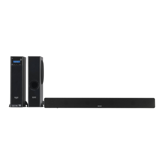
HT-SB600 Sound Bar system consisting of HT-SB600 (main unit), CP-SB600 (sound bar) and CP-SW600
(subwoofer).
HDMI
3
ARC
2
1
TV
LINE
L
DIGITA
2
1
2
1
TIMER
CLOCK
BAND)
TUNER(
TUNING
DIMMER
REBLE
MUTE
BASS/T
ZER
X-BASS
EQUALI
CENTE
R LEVEL
OFER LEVEL
SUBWO
T
PRESE
VOL
VOL
PRESE
T
TV
VOL
CHANN
EL
INPUT
Note:
This product is recommended for flat panel TV (LCD and plasma).
TINSEA363AWZZ
OPERATION MANUAL
SHARP ELECTRONICS OF CANADA LTD.
335 Britannia Road East, Mississauga,Ontario L4Z 1W9
ENGLISH
PRINTED IN MALAYSIA
11E R KI 1
Advertisement
Table of Contents

Related Manuals for Sharp HT-SB600


Summary of Contents for Sharp HT-SB600
-
Page 1: Operation Manual
SOUND BAR SYSTEM OPERATION MANUAL Thank you for purchasing this SHARP product. To obtain the best performance from this product, please read this manual carefully. It will guide you in operating your SHARP product. HT-SB600 Sound Bar system consisting of HT-SB600 (main unit), CP-SB600 (sound bar) and CP-SW600 (subwoofer). -
Page 2: Special Notes
Accessories The following accessories are included. AM Loop Aerial Remote Control Stand x 4 FM Aerial Wall Mount Angle x 2 Pattern Paper Speaker Wire Special Notes Manufactured under license under U.S. Patent Nos: ® ENERGY STAR Program Information 5,956,674; 5,974,380; 6,487,535 & other U.S. and worldwide patents issued &... -
Page 3: Limited Warranty
Sharp, a Sharp authorized service centre or a Sharp authorized servicing dealer. Any defects caused or repairs required as a result of the use of the Product with items not specified or approved by Sharp, including but not limited to, head cleaning tapes and chemical cleaning agents. -
Page 4: Volume Control
SHARP service facility. ● This unit should only be used within the range of 5°C - 35°C (41°F - 95°F). ● SHARP is not responsible for damage due to improper use. Refer all servicing to a SHARP authorised service centre. Warning: ●... -
Page 5: Controls And Indicators
Controls and indicators Front Panel Reference page 1. Remote Sensor ......15 2. Information Display ..... . . 16 3. -
Page 6: Rear Panel
Controls and indicators (continued) Rear Panel Reference page 1. Digital Input Socket ....13, 14 2. Line Input Socket ..... . 13, 14 3. - Page 7 Controls and indicators (continued) Sound Bar FRONT VIEW REAR VIEW Reference page 1. Left Front Speaker 5. Right Front Speaker terminal ....11 2. Bass Reflex Duct 6.
- Page 8 “ON” or switch the “STAND-BY”. input source. Volume Up Turn up/down Channel Up Switch up/ and Down the TV and Down down the TV Buttons volume. Buttons channels. Note: Some models of SHARP TV may not be operable.
-
Page 9: Speaker Preparation
Driving screws Installing the speaker SHARP designed the speakers so you may hang them on the wall. Use proper screws (not supplied). See below for Align the wall mount slot at the speaker to the wall size and type. -
Page 10: Placing The System
Placing the system Installation image: Placing the stand Place the stand as shown. SUBWOOFER SYSTEM Stand SUBWOOFER SYSTEM Subwoofer DVD player Main unit Place the system as shown. Remove the protective film covering the main unit and subwoofer before turn on the system. Notes: ●... -
Page 11: System Connections
System connections Make sure to unplug the AC power lead before making any connections. Main unit Subwoofer FM aerial Green White AM loop aerial Sound Bar Wall socket AC 120 V ~ 60 Hz SPEAKERS – FRONT INPUT CENTER WOOFER CAUTION: TO PREVENT ELECTRIC SHOCK, MATCH WIDE BLADE OF PLUG TO Purple... -
Page 12: Aerial Connection
Audio and Video signal the CEC. Example: Go to the Menu of the component to search and turn on the CEC. Different brands may have different naming for the CEC. For Sharp LCD TV, it is named as AQUOS LINK. DVD/Blu-ray ●... -
Page 13: Audio Connections To Tvs, Dvd Players, Vcrs, Etc
Audio connections to TVs, DVD players, VCRs, etc. Other connection (without HDMI) The illustration below shows the flows of audio and video signals. Audio signal Video signal DVD/Blu-ray Disc Player VCR/Game console Digital tuner, etc. Notes: ● Refer to the operation manual of the equipment to be connected. ●... - Page 14 Audio connections to TVs, DVD players, VCRs, etc. (continued) Connecting a DVD player, etc. Connect to the DVD player with an optical digital audio cable or an audio cable. To audio output Blu-Ray/DVD Player/Digital tuner terminals To optical digital audio output terminal To the TV (video) Optical digital audio...
-
Page 15: Remote Control
Audio connections to TVs, DVD Remote Control (continued) players, VCRs, etc. (continued) Notes concerning use: ● Replace the batteries if the operating distance is To select DIGITAL IN 1 (optical input) or DIGITAL IN 2 reduced or if the operation becomes erratic. (coaxial input) function: On main unit: Press INPUT button repeatedly until ●... -
Page 16: General Control
General control Volume control Main unit operation: HDMI Press the VOLUME + button to DIGITAL LINE increase the volume and the ..CLOCK TIMER 99 100 VOLUME – button for decreasing. DIMMER TUNING TUNER(BAND) Remote control operation: EQUALIZER X-BASS BASS/TREBLE MUTE Press the VOL + button to increase the volume and the SUBWOOFER LEVEL... - Page 17 General control (continued) Bass control Audio Return Channel (ARC) (Audio Return Channel submenu) 1. Press the BASS/TREBLE The audio return channel (ARC) enables an HDMI ARC- button to select “BASS”. capable TV to send the audio stream to the HDMI OUT 2.
-
Page 18: Listening To The Radio
Listening to the radio Memorising a station HDMI You can store 40 FM and AM stations in memory and recall them at the push of a button. (Preset tuning) DIGITAL LINE CLOCK TIMER Perform steps 1 - 3 in “Tuning” on page 17. DIMMER TUNING TUNER(BAND) -
Page 19: Setting The Clock (Remote Control Only)
Setting the clock (Remote Control only) Timer operation (Remote Control only) By setting the unit to the correct time, you can use it not Setting the timer only as a clock but also for timer. In this example, the clock is set for the 12-hour (AM 12:00) SUBWOOFER LEVEL CENTER LEVEL display. -
Page 20: Operating The Tv With The Remote Control
(page 18). The timer setting is cancelled. Operating the TV with the remote control Other operable button You can operate Sharp TVs with this system’s remote control. Input Select Button Watching TV Point the remote control at the TV. -
Page 21: Troubleshooting Chart
Many potential problems can be resolved by the owner Remote control without calling a service technician. If something is wrong with this product, check the following Symptom Possible cause before calling your authorised SHARP dealer or service centre. ● ● The remote control Is the battery polarity... -
Page 22: Error Indicators And Warnings
Troubleshooting chart (continued) Error indicators and warnings Factory reset, clearing all memory When you fail to perform operations properly, the following messages are displayed on the unit. Make sure to disconnect all output and input cables Display Meaning attached to the unit before performing the factory reset. ●... -
Page 23: Specifications
Specifications As part of our policy of continuous improvement, SHARP Soundbar (Speaker Right / Centre / Left) reserves the right to make design and specification changes for product improvement without prior notice. The Type Full Range speaker system performance specification figures indicated are nominal 6.5 cm (2 -1/2") speaker...