Table of Contents
Advertisement
SAVE THIS MANUAL
FOR FUTURE REFERENCE
MODEL NO.
113.213853
DRILL PRESS WiTH
1/2 HP MOTOR
Serial
Number
Model and serial number
may be found at the rear of
the head.
You
should
record
both
model and serial number in
a safe place for future use.
CAUTION:
Read GENERAL
and ADDITIONAL
SAFETY
INSTRUCTIONS
carefully
®
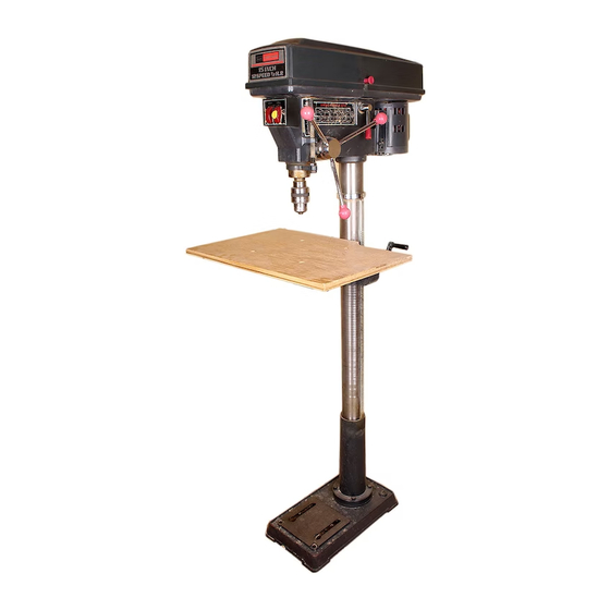
FLOOR
MOTORIZED
15 INCH
MODEL
DRILL
PRESS
• assembly
• operating
e repair parts
Sold
by SEARS,
ROEBUCK
AND
CO., Chicago,
IL. 60684
U.S.A.
PART NO. SP4964
PRINTED IN USA.
Advertisement
Table of Contents

Related Manuals for Craftsman 113.213853


Summary of Contents for Craftsman 113.213853
- Page 1 SAVE THIS MANUAL FOR FUTURE REFERENCE MODEL NO. 113.213853 DRILL PRESS WiTH 1/2 HP MOTOR Serial Number ® Model and serial number may be found at the rear of the head. MOTORIZED should record both 15 INCH model and serial number in a safe place for future use.
- Page 2 FULL ONE YEAR WARRANTY OhL CRAFTSMAN DRILL PRESS If within one year from the date of purchase, this Cra_sman Drill Press fails due to a defect in material or workmanship, Sears will repair it, free of charge. WARRANTY SERVICE IS AVAILABLE...
- Page 3 21. DiRECTiON OF FEED NEVER LEAVE TOOL RUNII_,,IING UNATTENDED Turn power off. Don't leave tool unti! it comes to a Feed work into a blade or cutter against the direc- tion of rotation of the blade or cutter only. comptete stop.
-
Page 4: Table Of Contents
it..il" add mona!safety mnstrucuons Tot ar ! presses c. Do not install or use any drill that exceeds 7" in 13, Think Safety. Safety is a combination of operator length or extends 6" below the chuck jaws. They common sense and alertness at all times when the can suddenly bend outward or break, drill press is being used. - Page 5 UNPACKING AND CHECKaNG TOOLS NEEDED CONTENTS Model No. 113.213853 is shipped complete in one car- ton and includes a 1/2 HP 1725 RPM motor. COMBiNAT_ Separate all parts from packing materials and check each one with the "Table of Loose Parts" to make certain all items are accounted for, before discarding any pack- COMBINATION SQUARE...
- Page 6 " " motor specifications and emectrmcaa e quirements MOTOR SPECIFICATIONS This power tool Is equipped with a 3-conductor cord This drill press is designed to use a 1725 RPM motor and grounding type plug which has a grounding prong, only. Do not use any motor that runs faster than 1725 approved by Underwriters' Laboratories and the Cana- RPM.
-
Page 7: Assembly
assembly WARNING: For your own safety, never connect plug to power source outlet until all assembly steps COLUMN are completed. ASSEMBLY OF COLUMN AND TABLE HARDWARE 1. Position base on floor. Remove protective covering and discard. 2. Remove protective sleeve from column tube and discard. -
Page 8: Installing The Head
assembly TABLE LOCK 2. Remove protective covering from table and discard. Place table in table support and tighten table lock TABLE (located under table) by hand. TABLE SUPPORT iNSTALLING THE HEAD CAUTION: The head assembly weighs about 55 HEAD pounds. Carefully lift head. 1. - Page 9 MOTOR PULLEY INSTALLING MOTOR PULLEY SET SCREW ___ 1. Loosen set screw in motor pulley using 1/8" HEX FLAT SURFACE "L" wrench, 2, Slide pulley onto motor shaft. Line up the flat surface on the motor shaft with the set screw in pulley. 3.
- Page 10 assembly 7. Locate center pul ey and place in proper hole. SPINDLE PULLEY IDLER PULLEY 8, Locate two (2) V-belts and choose speed for drilling operation. Install belts in correct position for desired speed. The shorter of the two belts is always positioned between spindle pulley and idler pulley.
- Page 11 MOTOR CONNECTIONS WARNING: For your own safety, never connect plug to power source outlet until all assembly steps LACK WIRE are completed. TERMINAL 1. Open motor connector box cover located on under- COPPER POST side of motor using a flat blade screwdriver. GREEN WIRE TO GREEN...
- Page 12 assembly 1. Clean out the TAPERED HOLE in the chuck; clean the spindle nose with a clean cloth. Make sure there are no foreign particles sticking to the surfaces. The slightest piece of dirt on the spindle nose or in the chuck will prevent the chuck from seating properly, This will cause the drill to "wobble."...
-
Page 13: Installing Light Bulb
INSTALLING LIGHT BULB 1. Install a light bulb (not larger than 60 watt) into the socket inside the head. ADJUSTING THE TABLE SQUARE TO HEAD NOTE: The combination square must be "true". See "Unpacking and Checking Contents" section method. Insert a precision ground steel rod approximately 3" long into chuck and tighten. -
Page 14: Getting To Know Your Drill Press
getting to know your drill press DEPTH SCALE DRILL "ON-OFF" BELT GUARD FEED SPRING SWITCH DEPTH POINTER ADJUSTMENT LIGHT "ON-OFF" FEED SWITCH BELT TE N SION SPRI NG BELT TENSION LOCK HANDLE STOP iLT TENSION FEED STOP ROD LOCK HANDLE CHUCK LOCKING HEAD LOCK COLLAR... - Page 15 This Drill Press has 12 speeds as listed below: SPINDLE SPEEDS iN R.P, Mo 300 RPM 1450 RPM 375 RPM 1530 RPM 525 RPM 2000 RPM 1450 1530 560 RPM 2200 RPM 700 RPM 3400 RPM 2000 2200 4600 860 RPM 4600 RPM ®...
- Page 16 geffing to know your drill press 26. DRILL "'ON-OFF" SWITCH... Has locking fea- ture. THIS FEATURE IS INTENDED TO HELP PREVENT UNAUTHORIZED AND "POSSIBLE HAZARDOUS CHILDREN OTHERS. Insert KEY into switch. NOTE: Key is made of yellow plastic. JI II IL_-__ r" To turn drill ON..
-
Page 17: Removing The Chuck
CHUCK DRiLLiNG SPEED... Can be changed by placing the KEY... It is a self-ejecting chuck key which belt in any of the STEPS (grooves) in the pulleys. See will "pop" out of the chuck when you let go of it. This Spindle Speed chart on right side of Head. -
Page 18: Basic Drill Press Operation
" n basic driJm press operatmo Follow the following instructions for operating your drill Never perform operation "FREE- HAND" (hand-holding workpiece rather press to get the best results and to minimize the I keli- hood pf personal injury. than supporting it on the table), except when polishing. -
Page 19: Positioning Table And Workpiece
POSITIONING TABLE AND WORKPIECE Lock the table to the column in a position so that the tip of the drill is just a little above the top of the work- piece. Always place a piece of BACK-UP MATERIAL (wood, plywood...) on the table underneath the workpiece. -
Page 20: Hole Location
basic drill press operation WARNING: TO avoid injury from spinning work or Before turning the switch ON, bring the drill down to tool breakage, always clamp workpiece and back- the workpiece lining it up with the hole location. up material securely to table before operating Drill Press with the table tilted. -
Page 21: Maintenance
maintenance WARNING: For your own safety, turn switch "OFF" and remove plug from power source outlet before maintaining or lubricating your drill press. Frequently blow out any dust that may accumulate in- side the motor. A coat of automobile-type wax applied to the table and column will help to keep the surfaces clean. -
Page 22: Trouble Shooting
trouble shooting WARNING: For your Own safety, turn switch "OFF" and always remove plug from power source outlet before trouble shooting. O CONSULT YOUR LOCAL SEARS SERVICE CENTER IF FOR ANY REASON MOTOR WILL NOT RUN. TROUBLE PROBABLE CAUSE REMEDY 1. - Page 23 PARTS LiST FOR CRAFTSMAN 15" DRILL PRESS MODEL NO. 113.213853 24 _ FIGURE 1 Part Part Description Description 71385 Tube, Column 71354 Pin, Gear 71320 Collar, Rack 71373 Spacer STD 502503 *Screw, Soc. Set 1/4-20x3/8 71332 Gear, Helical...
- Page 24 _i_ '_i_i! PARTS LiST FOR CRAFTSMAN 15" DRILL PRESS MODEL NO. 113.213853 • Any attempt to repair this motor may create a HAZARD unless repair is done by a qualified service technician. Repair service is available at your nearest Sears Store.
- Page 25 PARTS LiST FOR CRAFTSMAN 15" DRILL PRESS MODEL NO. 113.213853 FIGURE 2 ALWAYS ORDER BY PART NO. - NOT BY KEY NO. Part Part Description Description *Belt "V" 3/8x24 71338 STD 303240 Key, Chuck 60520 60522 Screw, Slotted Set Flat Ring, Retaining Pt.
- Page 26 PARTS LIST FOR CRA_SMAN 15"DRILL PRESS MODEL NO. 113.213853 "! FIGURE 4 Description 60509 Ring, Retaining 21/32 STD 315235 *Bearing, Ball 17MM 71384 Tube, Quill 60503 Bearing, Thrust STD 315255 *Bearing, Ball 25MM 71374 Spindle Chuck 71318 STD 541150 *Nut, Hex 1/2-20 STD 522512 *Screw, Hex Hd.
- Page 27 NOTES:...
-
Page 28: Repair Parts
MOTORIZED 15 INCH FLOOR MODEL DRILL PRESS Now that you have purchased your 15 inch drill press should a need ever exist for repair parts or service, simply contact any Sears Service Center and most Sears, Roebuck and Co. stores. Be sure to provide all pertinent facts when you call or visit.