Table of Contents
Advertisement
//_
Save
This Manual
"_
For Future
Reference
MODEL NO.
'_!3.2'13!30
DRILL PRESS WITH
MAXIMUM
DD!ELOPED
2/3 HP MOTOR
Serial
Number
Model
and serial
number
may be found
at the rear of
the head.
You should
record
both
model
and
serial
number
in
a safe place
for future
use,
l lll
CAUTION:
READ ALL
iNSTRUCTIONS
CAREFULLY
MOTORIZED
I
EL
e assembly
e operating
• repair
parts
,L Pl
x,..
Sold by SEARS, ROEBUCK AND CO., Chicago,
tL 60684
U.S.A.
Part No. SP5186
Printed in ÷_;, _"_,_
Advertisement
Table of Contents

Related Manuals for Craftsman 113.213130


Summary of Contents for Craftsman 113.213130
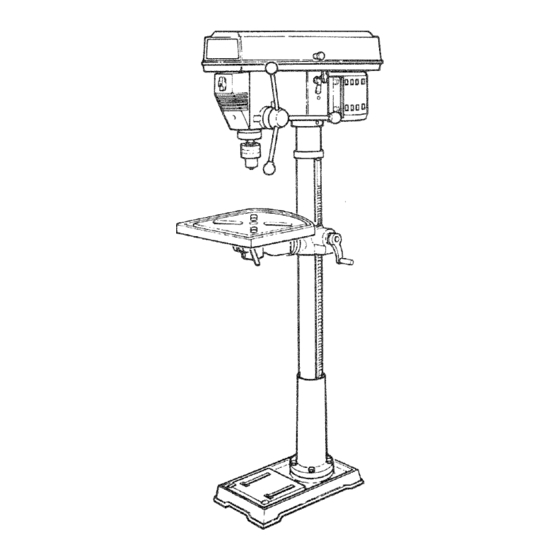
- Page 1 Save This Manual "_ For Future Reference MODEL NO. '_!3.2'13!30 DRILL PRESS WITH MAXIMUM DD!ELOPED 2/3 HP MOTOR Serial Number Model and serial number may be found at the rear of the head. You should record both model serial number a safe place for future use,...
- Page 2 FULL ONE YEAR WARRANTY ON CRAFTSMAN DRILL PRESS If within one year from the date of purchase, this Craftsman Drill Press fails due to a defect in material or workmanship, Sears will repair it, free of charge. WARRANTY SERVICE IS AVAILABLE BY SIMPLY CONTACTING THE NEAREST SEARS SER- ViCE CENTER!DEPARTMENT THROUGHOUT THE UNITED STATES.
- Page 3 additional safety instructions for drill presses d. To prevent the workpiece from being WARNING: FOR YOUR OWN SAFETY, DO NOT torn from your hands, spinning of the USE YOUR DRILL PRESS UNTIL mT IS COM- tool, shattering the too/or being thrown, PLETELY ASSEMBLED AND INSTALLED ACCORD- always properly support your work so ING TO THE INSTRUCTIONS...
- Page 4 _:_ Dum NEVER be operated ths dd pi'e_ at a _ed g_eater than t800 Do _ot inStait o_ ,,,_seany driP!that exceeds 7" in engt_ 0 e×te_tds 6!t'below the Chuck aws. They car_ S_dden_y be_d outward o_ break, Do not Use Wire wheets, _outer bits shaper cut- ters...
-
Page 5: Table Of Contents
gaossary of terms 1. Workpiece 4. Revolution Per Minute (R.P.M.) The item or_ which the cutti_'_g operations is being number of turns ,,:ompleled by a sp_nn_ng object in one minute performed. 2. Drill 5. Spindle Speed The cutting tool used in the drii_ press to make hotes The RPM of the spindie. - Page 6 requirements motor specifications electrical MOTOR SPECiFICATiONS This power tool is equipped with a 3-conductor cord and grounding type plug, approved by Underwriters' ThiS drili press is designed to use a 1725 RPM motor Laboratories and the Canadian Standards Association. only. Do not use any motor that runs faster than t725 The ground conductor has a green jacket and is at- RPM, It is wired for operation on 1 t 0-120 volts, 60 Hz.
- Page 7 unpacking and checking contents WARNING: AVOID iNJURY FROM UNEX- TABLE OF LOOSE PARTS PECTED STARTING OR ELECTRICAL SHOCK, item Description NOT PLUG THE POWER CORD INTO A SOURCE Tab!e OF POWER. THIS CORD MUST REMAIN UNPLUG- Column SUppori Asm. WHENEVER WORKING ON THE Owner s Manual...
- Page 8 List of Loose Parts in Box 507872 /_'_/' ,tern Description Qty. _LU_ \ I1_' Rod ...... B Knob ...."_ --:f C Crank ......D Screw Soc. Set M6 x 1.0-10 .... E Clamp-Column,,....... F Wrench-Hex"L 3mm ....G Wrench-Hex "L" 4mm ....-- Bag of Loose Parts (Not Shown) ..
- Page 9 mecation and functien ef centrols 9. CHUCK.., Holds drill bit or other recommended 1. BELTTENSION HANDLE..• Turn handle counter clockwise to apply tension to belt. turn handle accessory to perform desired operations. clockwise to release belt tension, 10. BEVEL SCALE, .
-
Page 10: Assembly Of Column
assembgy WARNING : FOR YOUR OWN SAFETY, NEVER CON" NECT PLUG TO POWER SOURCE OUTLET UNTIL ALL ASSEMBLY STEPS ARE COMPLETED. FRAMING SQUARE MUST BE TRUE. Check its accuracy as Illustrated belowo TOOLS NEEDED DRAW LIGHT STRAIGHT EDGE OF LiNE ON BOARD BOARD 3/4"... -
Page 11: Installing The Table
SUPPORT LOCK iNSTALLiNG THE TABLE TABLE 1. Loosen support lock and raise table support by turning table crank clockwise until support is at a working height level. Tighten support lock. TABLE SUPPORT RACK 2. Remove protective covering from table and dis- card. -
Page 12: Mounting Motor
MOUNTING MOTOR MOTOR BRACKET 1. Locate four (4) 8turn Dig × 20mrn long hex head ROUND OPENING bolts, eight (8) flat washers, and four (4) nex nuts MOTOR IN BELT GUARD BASE among loose parts. 2. Install hex head bolls through motor bracket... -
Page 13: Installing Belt Guard Knob
V-BELT SPINDLE PULLEY 5. Locate V-belt in the loose parts bag. 6. Use speed chart inside belt guard to choose speed for drilling operation. Install belt _n correct pos_t_on for desired speed NOTE: Refer to chart inside belt guard for Recc)m- mended Drilling Speeds. -
Page 14: Motor Connections
MOTOR CONNECTIONS WARNING: FOR YOUR OWN SAFETY- NEVER CON- NECT PLUG TO POWER SOURCE OUTLET UNTIL BLACK WIRE ALL ASSEt_BLY STEPS ARE COMPL ETED, COPPER POST GREEN WIRE TO GREEN SCREW WARNING; TO &VOID ELECTROCUTION, NEVER CONNECT ANYTHING BUT THE GROUND WIRE STRAIN RELIEF... - Page 15 _SPINDLE SUPPORT LOCK 3. Unlock support lock and raise table so its about two (2) inches below tip of chuck. 4. Turn chuck sleeve clockwise and open jaws chuck comp_etefy 5. Turn feed handles counterclockwise ai]d force chuck against table untii chuck is secure. CHUCK SLEEVE FEED...
-
Page 16: Bevel Scale
ADJUSTING THE TABLE SQUARE TO HEAD NOTE: The comb _t_on sauare must be "true." See 'Unpacking Checking Contents" section method, 1 Insert a preciston ground steel roe approximately 3" long into chuck and tighten, 2. With table raised to working height and locked on column, place combination square flat on table be- side rod TABLE... -
Page 17: On-Off
getting to know your driUm press FEED SPRING ADJUSTMENT FEED BELT GUARD SPRING SPRING DRILL "ON-OFF" SWITCH BELT TENSION LOCK HANDLE BELT TENSION LOCK HANDLE TABLE LOCK BELT TENSION LOCK DEPTH HANDLE SCALE LOCK HEAD LOCK SET SCREWS BEVEL SCALE INDICATOR TABLE BEVEL LOCK FEED HANDLE... -
Page 18: Drilling
This Dr_ll Presshas 5 soeeds as listed below: 500 R3M 990 _>M 1500 qPM 2250 RPM 3t00 See inside of belt guard for specific placement of belts on pulleys, SPINDLE SPEE#S R.P.Mo 1500 3100 2250 DEPTH SCALE Shows depth of hole being 1. - Page 19 DRILL "ON-OFF" SWITCH . . , Has locking fea- ture. THIS FEATURE IS INTENDED TO HELP PREVENT UNAUTHORIZED POSSIBLE HAZARDOUS CHILDREN OTHERS. Insert KEY into switch. NOTE: Key is made of yellow plastic. To tum drill ON , . Insert finger under switch lever and puli.
- Page 20 i,'_i_ii_i_i_i_?, i_ i i_ DRILLING TO A SPECIFIC DEPTH" To drill a BLIND hole (not all the way through) to a ..given depth proCeed as follows, Mark the depth of the hole on the side of the work- piece. Loosen the depth scale !ock.
- Page 21 DEPTH SCALE LOCK 3. Turnthe depth scaleclockwise untilit stops, 4. Tighten the depth scalelock. 5. Thechuck willnowbeheldatthisdepth whenthe feedhandles arereleased. REMOVING CHUCK 1. Raise the table so it is about (2) two inches below the chuck, This will prevent the chuck falling a long distance when it is removed.
-
Page 22: Installing
basic d tl( press operation owthef0 owng nstruct ons for operating your dr -- Never do any work "FREEHAND" (hand- pres_ to get the best results and to minimize the likeli, hod ng workp ece rather than support lg t h oa o!persona injury, onthetab el e xcept when p olishing WARNING:... - Page 23 POSITIONING "TABLE AND WORKPIECE Lock the table to the column in a position so that the tip of the drill is just a little above the top of the work- piece. Always place a piece of BACK-UP MATERIAL (wood, plywood. , .) on the table underneath the workpiece.
-
Page 24: Hole Location
TILTING TABLE :VEL LOCK : : To use the table in a bevel ttilted) position, loosen the set screw under table bevel lock with Hex "L" wrenchl Loosen bevel Iodk With adjustabie Wrench: iTilt tab e to desired angle by reading bevel scale. tighten bevel lock and set screw. -
Page 25: Maintenance
maintenance WARNING YOUR SAFETY, TURN SW_TCH "OFF" AND REMOVE PLUG FROM POWER SOURCE OUTLET BEFORE MAINTAINRNG OR LUB- RICATaNG YOUR DRILL PRESS. Frequently blow out any dust that may accumulate in- side the motor. A coat of furniture-type paste wax applied to the table and column will help to keep the surfaces clean. - Page 26 trouble shooting WARNING: FOR YOUR OWN SAFETY TURN SWITCH "OFF" AND ALWAYS REMOVE PLUG FROM POWER SOURCE OUTLET BEFORE TROUBLE SHOOTING. e CONSULT YOUR LOCAL SEARS SERVICE CENTER IF FOR ANY REASON MOTOR WILL NOT RUN. TROUBLE PROBABLE CAUSE REMEDY 1.
- Page 27 PARTS LmST FOR CRAFTSMAN 13" DRILL PRESS MODEL NO. 113.213130 Always order by Part Number--Not by Key Number FIGURE 1 PARTS LiST Part Part Description Description * Belt-"V" 3/8 x 39 Screw-Pan Hd. M5 x 0.8-12 STD303390 816755-3 Nut-Hex 1 "-20 LH.
- Page 28 PARTS LIST FOR CRAFTSMAN 13" DRILL PRESS MODEL NO. 113.213130 FIGURE 2 PARTS LIST 22,,.,-'_(_ .._----49...
- Page 29 PARTS LIST CRAFTSMAN 13" DRILL PRESS ¢# MODEL NO. 113.213130 Always order by Part Number--Not by Key Number FIGURE 2 PARTS LIST Part Key I Description Description No. L_ %___ ===ae_=m *Connector-Wire STD375007 Head w/Pointer & Trim 817778-1 * Lockwasher-Ext. 5mm...
- Page 30 PARTS LiST FOR CRAFTSMAN 13" DRILL PRESS MODEL NO. 113.213130 Always order by Part Number--Not by Key Number FIGURE 3 PARTS LiST Part Part Description Description 817475 Screw-Soc. Set M6 x 1.0-10 Tube-Column 817391-1 817351 Rack 817392 Screw-Hex Hd. 5/8-11 x 1.25 817391 Screw-Hex Soc.
- Page 31 NOTES...
- Page 32 SERVmCE Now that you have purchased your '13-inch Drill Press, should a need ever exist for repair parts or service, simply contact any Sears Service Center and most Sears, Roebuck and Co. stores. Be sure to provide all pertinent facts when call or visit,...