Table of Contents
Advertisement
Available languages
Available languages
Quick Links
_truction
anu
®
rE lo..L"
3/4 Horsepower
(continuous
duty)
1-1/2 Horsepower
(maximum
developed)
16-Speed, Step Punmey
215 - 2720 R.P.M. Drill Speed Range
1
iLL P
SS
Ji
Model
No.
152.229010
C
S
FOR YOUR OWN SAFETY;
Read
and foUlow all of the Safety and
Operating
Instructions
before
Operating
this DdH Press.
Customer
Helpline
1-800-897-7709
PRease have your Model No.
and SedaR No. availabUe.
Sears, Roebuck
and Co., Hoffman
Estates,
JL 60179 U.S.A.
Part No. OR93513
EspaSoL pg, 31
Advertisement
Table of Contents

Related Manuals for Craftsman 152.229010


Summary of Contents for Craftsman 152.229010
- Page 1 _truction ® rE lo..L" 3/4 Horsepower (continuous duty) 1-1/2 Horsepower (maximum developed) 16-Speed, Step Punmey 215 - 2720 R.P.M. Drill Speed Range iLL P Model 152.229010 FOR YOUR OWN SAFETY; Read and foUlow all of the Safety and Operating Instructions before Operating this DdH Press.
- Page 2 Back Page ONE-YEAR FULL WARRANTY ON CRAFTSMAN TOOL if this Craftsman tool fails due to a defect in material or workmanship within one year from the date of purchase, CALL 1-800-4-MY-HOME _) TO ARRANGE FOR FREE REPAIR, This warranty applies only while this tool is in the United States,...
- Page 3 17°in. Drill Press with Laser°Trac Handle Operation 360 degree rotation Motor Specifications: Motor Control Industrial push button Motor type induction with OFF paddle Continuous duty HP Table Size 14" wide x 14" depth Maximum developedHP 1=1/2 Table Tilt Amps 10/5 Table Movement Rack and pinion Volts...
- Page 4 GENERAL SAFETY iNSTRUCTiONS AVOID ACCIDENTAL STARTING, Make sure that the power switch is in the "OFF" position before Operating a drill press can be dangerous if safety and plugging in the power cord to the electrical common sense are ignored, The operator must be receptacle, familiar with the operation of the tool, Read this manual to understand this drill press, DO NOT operate this drill...
- Page 5 GUIDEUNES 20, MAINTAIN TOOLS WITH CARE, Always keep tools clean and in good working order, Keep all blades EXTENSUON CORDS and tool bits sharp, The smaller the gauge-number, the larger diameter of 21, NEVER LEAVE A RUNNING TOOL UNATTENDED, the extension cord, if in doubt of the proper size of an Turn the power switch to the OFF position, DO extension cord, use a shorter and thicker cord, An NOT leave the tool until it has come to a complete...
- Page 6 USE ONLY A 3-WIRE EXTENSION CORD THAT HAS A 3-PRONG GROUNDING PLUG AND A 3-POLE THINS TOOL MUST BE GROUNDED WHmLE mNUSE RECEPTACLE THAT ACCEPTS THE TOOL'S PLUG. TO PROTECT THE OPERATOR FROM ELECTRmC REPLACE A DAMAGED OR WORN CORD IMMED- SHOCK.
- Page 7 it is aUsonecessary to repUace the 120 voUtpUug,sup- Before leaving the drill press, LOCK or REMOVE plied with the motor, with a UL/CSA Listed pUugsuitabb the ON/OFF switch/key to prevent unauthorized for 240 voUts and rated current of the drHU press. Contact use, a bcaU qualified eUectrbian for proper procedures to DO NOT install or use any drill bit that exceeds...
- Page 8 Sears may recommend other accessories not listed in this manual, Visit your Sears Hardware Department or see the Craftsman Power and Hand Tool Catalog for the follow- See your nearest Sears Hardware Department or ing accessories, Craftsman Power and Hand Tool Catalog for other...
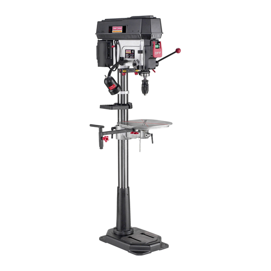
- Page 9 Figure 1, BeHtcover 2, ON/OFF switch 3, AdjustabHe feed handHes 4, QulH Hock 5, Laser (not shown) 6, KeyHess chuck 7, TaMe 8, CoHumn 9, Base 10, TaMe Extension 11, Tray 12, Depth scaHe 13, Motor 14, FHexibHe Hamp...
- Page 10 UNPACKUNG AND CHECKUNG CONTENTS Compare the items to figures below; verify that all items are accounted for before discarding the shipping box, This drHU press wHU require some amount of assemMy, if there are any missing parts, call Customer Helpline Remove aH of the parts from the shipping box and Uay 1-800-897-7709, them on a clean work surface,...
- Page 11 Figure TaMe extension TaMe rabe/Mower handle Adjustabie Feed handie Knob Spindie adapter remover Hex head screw MIO x 40mm (4) W, TaMe rotation Hockhandie TaMe extension support Knob (2) Keyiess chuck Tray, back TaMe height Hockhandie Chuck arbor Tray Hex head screw M8-1,25 x 125mm (4) 2,5mm Hex wrench CHamp pilate Fiat Washer M8 (8)
- Page 12 TOOLS REQUIRED Figure The following toob are needed for assemMy and align- ment. Note: hex wrenches are provided. The remaining toob are typbaU shop tooUsand are not included with your drHU press. 12mm Open end wrench 13mm Open end wrench #2 PhHHpsscrewdriver Hammer and Mock of wood The drHU press is a heavy machine;...
- Page 13 Figure Figure Hace the clamp plate (L) over the tame extension Hace tame extension (Q) into tame extension sup- support and attach it with two threaded knobs (M), port, See Figure 4-7, Figure Figure Assemble the threaded knob (R) into the weld nut (S) on the table extension support, See Figure 4-8, AssemMe the threaded end of the tame rotation...
- Page 14 Figure DRILL PRESS HEAD AND MOTOR ASSEMBLY The drHU press is a heavy machine; two peopb may be required for certain assemMy operations, MAKE CERTAIN the drHU press is disconnected from the power source, Figure 10, LooseUy assembb the tray back (T) to the tray (U) with two pan head screws M5 x 35mm (V) and M5 hex nuts (X), See Figure 4-9, Figure...
- Page 15 Figure Figure NOTE: Make certain that the spindie taper (G) and the tapered hob in the chuck (H) are clean and free of Piace adjustabie handie (D) onto quHi advancement grease, iacquer, or rust preventive coatings, shaft (E), See Figure 5-3, Figure 5-5 Househoid oven cieaner can effectiveiy remove any substance from the spindie and chuck,...
- Page 16 LASER ASSEMBLY Figure MAKE CERTAIN the drill press is disconnected from the power source, LASER LIGHT - DO NOT STARE INTO BEAM, APERTURE, or into a reflection from a mirrorqke surface, Figure Hace Uaser around coUumn (G) and against the head casting (H) and fasten the damp secureUy at the coUumn, Make sure Uaser housing is positioned so that one...
- Page 17 Figure DONOTexpose thedrillpressto rainor operate the in damplocations, MAKESUREallpartshavebeenassembled c orrectly andarein working order, SWITCH OPERATION CHmLDPROOF THE WORKSHOP AREA by removing switch keys, unplugging tools from the electrical recep- tacles, and using padlocks, Figure When the Drill Press is not in use, the "ON" button should be locked so that it cannot be started, Using the padlock (E) included with your Drill Press, lift the red iOFF[ paddle (C) and place the padlock...
- Page 18 FLEXUBLE LAMP TABLE OPERATION Figure 10-1 To reduce the risk of fire, use 40 watt or less, 120 volt, reflector track-type Hight buib (not supplied), DO NOT use a standard househoid Hight buib, The reflector track- type Hightbuib shouid not extend bellow the iamp shade, Figure ©...
- Page 19 Figure 10-3 Figure 10-4 20 o 10° A tilt scaUe (G) is provided on the tame bracket cast- The tame can be tilted right or Ueftby Uoosening the tame Uocking bout (U),then removing the tame align- ing to indicate the degree of tilt, A witness Hne (H) is ment pin (F), See Figure 10-3, provided on the tame to align with the tilt scaUe, See Figure 10-4,...
- Page 20 CHANGUNG SPEEDS DF_ULUNG HOLES TO DEPTH ADJUSTING BELT TENSUON MAKE CERTAIN the drHH press is disconnected from the power source, MAKE CERTAIN the drill press is disconnected from the power source, Figure 13-1 Figure 12-1 Open the beHtcover, See Figure 12-1, Loosen the tension lock knobs, one is on each side, Rotate the belt tension handleforward, away from...
- Page 21 ADJUSTING RETURN SPRING LASER ADJUSTMENTS The drHH chuck wHH automaticaHHyreturn showily to its upper position when the handHe is reHeased, The return ,, MAKE CERTAIN the drHH press is disconnected from spring was properHy adjusted at the factory, However, to the power source, adjust, if necessary: LASER LIGHT - gO NOT STARE INTO BEAM,...
- Page 22 Figure 15-3 Figure 15-5 Loosen the two screws (U)on the face (J) of the bft side Uaser, See Figure 15-3, On the alignment pin (A) there is a verticaU fine scribe (L) into it, This is used to set parafleHsm of the Uasers, See Figure 15-4, Adjust the drill press table so that it is about 1"...
- Page 23 iNSTALLiNG AND REMOVING DRULL BITS SUPPORTING WOF{KPIECE USE onUyrecommended accessories. MAKE CERTAIN the drill press is disconnected from the power source. Figure 17-1 Figure 18-1 IMPORTANT: When the workpiece (A) is long enough, position it on the table with one end against the left side of the column (B) to prevent the workpiece from rotat- HoUdthe collar (A) and turn the chuck barreU (B) ing.
- Page 24 TABLE EXTENSUON Figure 18-2 Figure 19-1 While the handUe (A) is disengaged, rotate it to the desired position and reUease the handUe, The ham due is spring Uoaded and wHU engage by Ueave it at rest, Figure 19-2 Figure 18-3 To move the table extension support (A), loosen the two knobs (B) under the table (C), See Figures 19-1 and 19-2,...
- Page 25 DRULUNG OPERATION CORRECT DRiLLiNG SPEEDS Factors that determine the correct speed are: the work- Use a center punch to dent the workpiece where you piece, the size of the hob, the type of bit or other cutter, want the hob. This will keep the bit from walking when and the quality of cut wanted, you start the drill operation.
- Page 26 CHANGmNG LASER BATTERY Turn the power switch OFF and unplug the power Turn the power switch OFF and unplug the power cord cord from its power source, from its power source, LASER UGHT - DO NOT STARE mNTOBEAM, The drill press has sealed lubricated bearings in the APERTURE, or into a reflection from a mirror-like surface,...
- Page 27 TOPREVENT I NJURY TOYOURSELF o r damage to theddH press, t urntheswitchtotheOFFposition andunpUug thepower cordfromtheeUectrbaU receptacle b efore making anyadjustments, PROBLEM SOLUTION UKELY CAUSE(S) Motor does 1. Switch key is removed. 1. insert switch key. not start or 2. Defective switch. 2.
- Page 28 17-in.BenchDrill Press MODEL N0.152.229010 Whenservicing, useonUy C RAFTSMAN r epUacement parts,Useof anyotherpartsmaycreatea HAZARD or cause product d amage, Anyattempt t o repair o r repUace electrbaU p artsonthisdrHU p ressmaycreatea HAZARD unbssa quarried service technician d oesrepairs, R epair s erviceis avaHabb a tyournearest S earsService Center, Always orderby PART NUMBER, notbykeynumber, PART PART...
- Page 29 17-in. Bench Drill Press MODEL N0.152.229010 (2_. 151 (6)_ 158--_ (2)_ I_158 /141 119 (2) 52 / 103 (4}_ 102 (4)_ i01 {g)_...
- Page 31 ® 3/4 Cabaiios de Fuerza (servicio continuo) 1-1/2 Cabalios de Fuerza (ma×imo desarroiiado) 16 Velocidades, Poiea Escalonada Gama de VeNocidades de Perforacidn 215-2720 R.P.M Modelo No. 152.229010 PARA SU SEGURJDAD PERSONAL, Reay obedezca todas Uas lnstrucciones Seguddad y Operaci6n antes de operar esta Taladradora de Banco Linea de Ayuda al CLiente...
- Page 32 GARANTiA COMPLETA DE UN ANO PARA LAS HERRAMIENTAS CRAFTSMAN Siesta herramienta Craftsman Ibgase a failar debido a defectos materiabs o de elaboraci6n dentro de un aho a partir de la fecha de compra, LLAME AL 1-800-4-MY*HQME @ (en EE,UU,) PARA CQQRDINAR...
- Page 33 Ta[adradora de Banco de 17 pu[g° con Laser°Trac Dimensiones de mesa 14 pulg. de ancho x 14 pulg. de profundidad IncJinaci6n de mesa _ecificaciones deI Motor: Movimiento de mesa Tipo de motor Inducci6n Cremalbra y pih6n Servicio continuo 3/4 HP Maximo desarrollado 1-1/2 HP Material de mesa...
- Page 34 INSTRUCCIONES GENERALES EVITE LOS ARRANQUES ACCIDENTALES. Aseg0rese de que el interrupter de energ[a se encuentre en la posi- DE SEGURIDAD ci6n de "OFF" (apagado) antes de enchufar el cord6n de El uso de una taIadradora puede ser peligroso si se hace potencia y causar dare a la herramienta.
- Page 35 21. NUNCA D EJE UNA M_,QU_NA ENFUNCJONAM_ENTO DIRECTRJCES PARA LAS SiNATENDER A pague e linterrupter deenerg[a a Ia EXTENSUONES ELECTRICAS posici6n de"OFF" (apagado). NOsealeje deJamb, quina hasta que sehaya detenido percompbto. Mientras menor sea el n0mero de calibre, mayor sera el diametro de la extensi6n electrica.
- Page 36 REPONGA _NMEDJATAMENTE CUALQUJER CORDON DANADO O GASTADO. ESTA HERRAM_ENTA DEBE ESTAR CONECTADA PARA MAQUINAS CONECTADAS A TJERRA, CONEC- TIERRA DURANTE EL USO PARA PROTEGER AL TADAS POR CORDON, DJSENADAS PARA EL USO EN OPERAR_O CONTRA LOS CHOQUES ELECTR_COS. UN CIRCUJTO DE SUM_N_STRO QUE TENGA UNA CLASJFJCAC_0N NOMINAL _NFERJOR A LOS 150 EN EL CASO DE UN MALFUNCJONAMJENTO...
- Page 37 REVISE todas Ias brocas, herramientas de corte, tam- Tambien sera necesario reemplazar el enchufe de 120 voltios suministrado con el motor con un enchufe aprobado por bores de lijado u otros accesorios antes de instalarJas en UL/CSA y apto para el funcbnamiento a 240 voltios y la el mandrino de la taladradora por si existen seFiales de...
- Page 38 Visite su Departamento de Ferreteffa Sears o consuIte el CataJogo de Herramientas Manuales y Mecanicas de Consulte con su Departamento de Ferreter[a Sears mAs cer- Craftsman para los siguientes accesorios: cano o su Catalogo de Herramientas Manuabs y Mecanicas de Craftsman para otros accesofios.
- Page 39 Figura Cubierta de la correa hterruptor de ENCENDIDO/APAGADO Agarraderas de alimentaci6n ajustables Cierre del Arbol hueco LAser (no ilustrado) Mandrino sin Ilave Mesa Columna Base 10. Extensi6n de mesa 11. Bandeia 12. EscaJa de profundidad 13. Motor 14. Lampara flexible...
- Page 40 DESEMPAQUE Y COTEJO Asegurese de frotar la cera para eliminada antes dei montaje. DEL CONTENIDO Compare los art[culos con la Figura 3-1 abajo y compruebe que todos los art[culos esten contabilizados antes de descar- Esta taladradora necesitara cierta cantidad de montaje. Quite tar Ia caja de envio.
- Page 41 Figura Extensi6n de mesa Agarradera de [zado / bajada de la Agarradera de al[mentaci6n ajustable mesa PerilIa Tornillo de cabeza hexagonal Desmontador del adaptador del huso M10 x 40 mm (4) Soporte de la extensl6n de mesa PeriIIa (2) W. Agarradera de c[erre de rotac[6n de mesa Mandrino sin Ilave Bandeja, dorso Agarradera de c[erre de altura de mesa...
- Page 42 HERRAMUENTAS REQUERUBAS Figura Se requieren Ias siguientes herramientas para el montaje y alineaci6n. Aviso: Se proporcionan las Ilaves hexagonales. Las herramientas restantes son herramientas t[picas de taller que no estan incluidas con su taladradora. Llave de boca de 12 mm Llave de boca de 13 mm Destornillador Phillips #2...
- Page 43 Figura Figura Coloque la placa de la abrazadera (L) sobre eI soporte Coloque la extensi6n de mesa (Q) en el soporte de de extensi6n de la mesa y conectela con dos perillas extensi6n de mesa. Ver Figura 4-7. roscadas (M). Figura Figura Enrosque Ia perilIa roscada (R) a la tuerca soldada (S)
- Page 44 Figura MONTAJE DEL CABEZAL MOTOR DE LA TALADRADORA La taladradora es una maquina pesada. Podran requedrse dos personas para ciertas operaciones de montaje, o ASEGORESE de que Ia taladradora este desenchufada la fuente de suministro, Figura 10, Monte sueltamente e! dorso de la bandeja (T) a la bande- ja (U) con dos tornilIos de cabeza troncoc6nica M5 x 35 mm (V) y tuercas hexagonales...
- Page 45 Figura Figura AVJSO: Aseg0rese de que la parte ahusada del huso (G) y eI agujero ahusado en eI mandfino (H) se encuentren Iimpios y Coloque la agarradera ajustable (D) sobre el eje de fibres de grasa, Iaca o revestimientos antioxidantes, Ver la avarice del b,rbol hueco (E), Ver la Figura 5-3, Figura 5-5, Los limpiadores para homes domesticos...
- Page 46 ENSAMBLADO DEL LASER Figura o ASEGURESE de que la taiadradora este desconectada la fuente de energ[a. o LUZ LASER - NO MIRE EL HAZ, LA APERTURA tampoco el refiejo de una superficie espejada. Figura Coloque el laser alrededor de la columna (G) y contra la pieza fundida del cabezal (H), afianzando la abrazadera de manera segura en la columna.
- Page 47 Figura o NO exponga la taladradora a Ja Jluvia ni tampoco Ja opere en Jugares hOmedos. ASEGURESE de que todas las piezas hayan sido correcta- mente montadas y esten en funcionamiento. OPERACION DEL CONMUTADOR HAGA SU TALLER A PRUEBA DE NINOS quitando las Jlaves de los interruptores, desenchufando Ias herramientas de los tomacorrientes...
- Page 48 LAMPARA FLEXIBLE OPERACION DE LA MESA Figura 10-1 Para reducir el peIigro de incendios, utilice una bombilla de 40 vatios o menos, 120 voltios tipo reflector (no suministrado). NO UTILICE una bombilIa domestica estandar. La bombilla tipo reflector no debe extenderse mas alia de la pantalla de la lampara, Figura ©...
- Page 49 Figura 10-3 Figura 10-4 20 o 10° La mesa puede inclinarse a la derecha o izqu+erda afio- Se proporciona una escala de inclinaci6n (G) sobre Ea jando el perno de cierre de Ia mesa (H)y Iuego quitando pieza fundida del soporte de la mesa. Se proporciona el pasador de alineaci6n de mesa (F).
- Page 50 CAMBIANDO VELOCIDADES PERFORANDO AGUJEROS AJUSTANDO LA TENSI6N DE LA CORREA PROFUNDIDAD ASEGURESE de que la taladradora este desconectada de Ja ASEGURESE de que Jataladradora este desconectada de la fuente de energfa, fuente de energ[a, Figura 12-1 Figura 13-1 Abra Jacubierta de Ia correa, Ver Ia Figura 12-1, Afioje Jas perillas de cierre de tensi6n, una a cada lado, Gire Ia agarradera de tensi6n de correa hacia adelante y alejada del motor,...
- Page 51 AJUSTANDO EL RESORTE DE RETORNO AJUSTES DEL LASER El mandrino de la taladradora regresara Ientamente y de forma automatica a su posici6n superior aI soltar la agarra- dera. El resorte de retorno fue ajustado correctamente en Ia ASEGURESE de que la taladradora este desconectada fabrica= Sin embargo, si resuIta necesario efectuar ajustes: la fuente de energfa=...
- Page 52 Figura 15-3 Figura 15-5 Afloje los dos tornillos d) sobre la cara (J) del laser del lade izquierdo. Ver la Figura 15-3. En e! pasador de alineaci6n (A) existe una I[nea vertical de trazado (L). Esto se utiliza para establecer el parale- lismo de los laseres.
- Page 53 INSTALACI6N Y DESMONTAJE APOYANDO EL MATERIAL DE BROCAS SOLO utilice accesorios recomendados. ASEGURESE de que la taladradora este desconectada de la Figura 17-1 fuente de energfa. Figura 18-1 tMPORTANTE: Si el material (A) sea Io suficientemente largo, posici6nelo sobre la mesa con un extreme contra el lade izquierdo de Ia columna (B) para impedir que el material gire.
- Page 54 EXTENSION DE MESA Figura 18-2 Figura 19-1 Cuando la agarradera (A) este desengranada, gffela a Ia posici6n deseada y suelte Ia agarradera. La agarradera est9, cargada con resorte y se reengranar_i por s( sola al dejada descansar. Figura 19-2 Figura 18-3 Para mover el soporte de extensi6n de mesa (A), afloje las dos perilIas (B) bajo la mesa (C).
- Page 55 VELOCIDADES DE PERFORACION Durante Ia perforaci6n de metabs sera necesano lubncar la punta de la broca con aceite para impedir su sobrecabnta- APROPIADAS miento. Los factores que determinan Ia mqor velocidad a ser utiIizada en cualquier funci6n de taladrado son: eI tipo de material a OPERACI6N DE PERFORACI6N ser elaborado, el tamaflo del agujero, tipo de broca u otra...
- Page 56 CAMB[ANDO LA BATERiA DEL LASER LUBRICAC[ON APAGUE el interrupter y desenchufe el cord6n de energfa APAGUE el interrupter y desenchufe el cord6n de energfa de de su fuente de suministro. la fuente de sumin[stro. o LUZ LASER - NO M_RE EL HAZ, LA APERTURA ni tam- La taladradora tiene cojinetes lubricados se[Iados en eI...
- Page 57 PARA EVSTAR HERIRSE A Si rWlSMO o causar daf_o a la taladradora, conmute el interruptor a la posici6n de apagado (OFF) y desenchufe el cord6n de energ[a del tomacorrientes antes de realizar cuaIquier ajuste= PROBLEMA CAUSA(S} POSIBLES SOLUCJ6N Motor 130 arranca 1.
- Page 58 Taladradora de Banco de 12 Pumg, NO. DE MODELO 152,229010 Cuando vaya a rendir servicio, s6Jo utiIice piezas de recambio CRAFTSMAN. El uso de cuatquier otro tipo de piezas podra crear un PEUGRO o producir dahe aJ producto. Cualquier intento per reparar o reempIazar Ins plazas etectricas de esta taIadradora podrb, crear un PEUGRO a menos qua Ja reparaci6n sea efectuada per un tecnico de servicio competente.
- Page 59 Tatadradora de Banco de 12 Pumg, NO, DE MODELO 152,229010 (2_. 151 (6)_ 6 #_(4) 158--_ (2)_ I_158 /141 119 (2) 52 / 103 (4}_ 102 (4)_ i01 {g)_ (4)_...
- Page 60 Your Home For repair-in your home-of all major brand appliances, lawn and garden equipment, or heating and cooling systems, no matter who made it, no matter who sold it! For,the replacement parts, accessories owner s manuals that you need to do-it-yourself. For Sears professional installation of home appliances and items like garage door openers...