Table of Contents
Advertisement
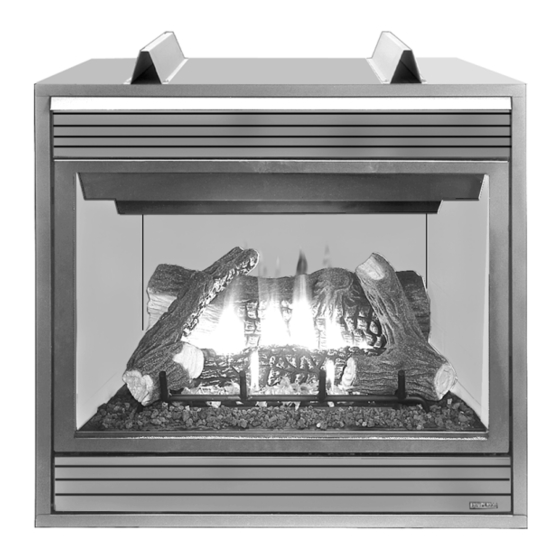
DR-500 MODEL SHOWN
RETAIN THESE INSTRUCTIONS
FOR FUTURE REFERENCE
WARNING: IF THE INFORMATION IN THIS MANUAL
IS NOT FOLLOWED EXACTLY, A FIRE OR EXPLO-
SION MAY RESULT CAUSING PROPERTY DAM-
AGE, PERSONAL INJURY OR LOSS OF LIFE.
FOR YOUR SAFETY: Do not store or use gasoline
or other flammable vapors or liquids in the vicin-
ity of this or any other appliance.
FOR YOUR SAFETY: What to do if you smell gas:
• DO NOT light any appliance.
• DO NOT touch any electrical switches.
• DO NOT use any phone in your building.
• Immediately call your gas supplier from a
neighbor's phone.
Follow your gas suppliers instructions.
• If your gas supplier cannot be reached, call the
fire department.
Installation and service must be performed by a
qualified installer, service agency or the gas
supplier.
OTL Report No. 116-F-13-4
NOTE: DIAGRAMS & ILLUSTRATIONS NOT TO SCALE.
HOMEOWNER'S CARE AND
OPERATION INSTRUCTIONS
DIRECT-VENT
500/600/800 SERIES
VENTED GAS FIREPLACE HEATERS - DIRECT VENT MODELS
P/N 725,032M REV. H 11/2004
MODELS
M
l i
v i l
t l o
M
o
e d
s l
D
5 -
0 0
C
M
N
D
T
6 -
0 0
D
5 -
0 0
C
M
P
D
R
6 -
0 0
D
T
5 -
0 0
C
M
N
D
R
6 -
0 0
D
T
5 -
0 0
C
M
P
D
8 -
0 0
C
D
R
5 -
0 0
C
M
N
D
8 -
0 0
C
D
R
5 -
0 0
C
M
P
D
T
8 -
0 0
D
6 -
0 0
C
M
N
D
T
8 -
0 0
D
6 -
0 0
C
M
P
D
R
8 -
0 0
D
T
6 -
0 0
C
M
N
D
R
8 -
0 0
AVERTISSEMENT: ASSUREZ-VOUS DE BIEN SUIVRE
LES INSTRUCTIONS DONNÉ DANS CETTE NOTICE POUR
RÉDUIRE AU MINIMUM LE RISQUE D'INCENDIE OU
POUR ÉVITER TOUT DOMMAGE MATÉRIEL, TOUTE
BLESSURE OU LA MORT.
POUR VOTRE SÉCURITÉ: Ne pas entreposer ni utiliser
d'essence ni d'autre vapeurs ou liquides inflammables
dans le voisinage de cet appareil ou de tout autre
appareil.
POUR VOTRE SÉCURITÉ: Que faire si vous sentez une
odeur de gaz:
• Ne pas tenter d'allumer d'appareil.
• Ne touchez à aucun interrupteur. Ne pas vous servir
des téléphones se trouvant dans le batiment où
vous vous trouvez.
• Evacuez la piéce, le bâtiment ou la zone.
• Appelez immédiatement votre fournisseur de gaz
depuis un voisin. Suivez les instructions du
fournisseur.
• Si vous ne pouvez rejoindre le fournisseur de gaz,
appelez le service dos incendies.
L'installation et service doit être exécuté par un qualifié
installeur, agence de service ou le fournisseur de gaz.
E
e l
r t c
n o
c i
M
C
M
P
D
5 -
0 0
C
E
N
D
C
M
N
D
5 -
0 0
C
E
P
D
C
M
P
D
T
5 -
0 0
C
E
N
D
M
N
D
T
5 -
0 0
C
E
P
M
P
D
R
5 -
0 0
C
E
N
C
M
N
D
R
5 -
0 0
C
E
P
D
C
M
P
D
6 -
0 0
C
E
N
D
C
M
N
D
6 -
0 0
C
E
P
D
C
M
P
D
T
6 -
0 0
C
E
N
D
o
e d
s l
T
6 -
0 0
C
E
P
R
6 -
0 0
C
E
N
R
6 -
0 0
C
E
P
D
8 -
0 0
C
E
N
D
8 -
0 0
C
E
P
T
8 -
0 0
C
E
N
T
8 -
0 0
C
E
P
R
8 -
0 0
C
E
N
R
8 -
0 0
C
E
P
1
Advertisement
Table of Contents
Troubleshooting

Related Manuals for Superior DR500 SERIES


Summary of Contents for Superior DR500 SERIES
-
Page 1: Operation Instructions
HOMEOWNER'S CARE AND OPERATION INSTRUCTIONS DIRECT-VENT 500/600/800 SERIES VENTED GAS FIREPLACE HEATERS - DIRECT VENT MODELS P/N 725,032M REV. H 11/2004 MODELS v i l t l o r t c DR-500 MODEL SHOWN RETAIN THESE INSTRUCTIONS FOR FUTURE REFERENCE AVERTISSEMENT: ASSUREZ-VOUS DE BIEN SUIVRE LES INSTRUCTIONS DONNÉ... -
Page 2: Table Of Contents
GENERAL INFORMATION Note: Installation and repair should be per- In selecting this SUPERIOR Direct-Vent Gas Appliance you have chosen the finest and formed by a qualified service person. The appli- most dependable fireplace to be found anywhere. A beautiful, prestigious, alternative to ance should be inspected annually by a quali- a wood burning fireplace. -
Page 3: Operation/Care Of Your Appliance
The following table shows the units' orifice size WARNING: FAILURE TO COMPLY for the elevations indicated. WITH THE INSTALLATION AND OP- ERATING INSTRUCTIONS PROVIDED IN THIS DOCUMENT WILL RESULT IN i f i AN IMPROPERLY INSTALLED AND OP- ERATING APPLIANCE, VOIDING ITS WARRANTY. -
Page 4: Variable Flame Adjustment
Electronic Appliances - To light electronic appliances refer to the de- Variable Flame Height Adjustment Inlet Pressure Port tailed lighting instructions found in both En- Manifold Pressure Port glish and French on pages 14 and 15 of these instructions respectively. Electronic appliance lighting instructions may also be found on the pull out lighting instruction labels at- tached to the gas control valve. -
Page 5: Maintenance Schedule
Maintenance Schedule Annually (Before the onset of the Burning Season) Maintenance Task Accomplishing Person Procedure Inspecting/Cleaning Burner, Logs Qualified Service Technician Inspect valve and ensure it is properly operating. and Controls Check piping for leaks. Vacuum the control compartment, fireplace logs and burner area. Check Flame Patterns and Flame Height Qualified Service Technician Refer to Figure 7 (D, DT, DR-500), 8 (D,... -
Page 6: Front Glass Enclosure Panel, Removal And Installation
Sooting is caused by incomplete combustion in Front Glass Enclosure Panel, Removal 4. Swing the bottom of the door out and raise it slightly to lift the top flange of the door frame the flames and a lack of combustion air entering and Installation. -
Page 7: Log Placement
Carefully position the ceramic fiber logs and twigs over the burner as shown in Figure 7 (D, DR, DR-500), 8 (D, DT,DR-600) or 9 (D, DT, DR-800) . For more detailed placement instructions, refer to the LOG PLACEMENT GUIDE accompanying this document. Proper twig placement is critical to prevent sooting. -
Page 8: Rockwool Placement
Glowing Embers (Rockwool) Placement To light the burner, refer to the lighting in- Electronic Appliance Checkout structions on pages 11 and 12 for Honeywell To light the burner, refer to the lighting instruc- Refer to the detailed glowing embers place- and SIT millivolt gas valves). -
Page 9: Wiring Diagrams
WIRING DIAGRAMS Wiring diagrams are provided here for reference purposes only. This information is also provided on schematics attached directly to the appliance on a pullout panel located within the control compartment. CAUTION: LABEL ALL WIRES PRIOR TO DISCONNECTION WHEN SERVICING CONTROLS. WIRING ERRORS CAN CAUSE IMPROPER AND DANGEROUS APPLIANCE OPERATION. -
Page 10: Accessory Components
ACCESSORY COMPONENTS Forced Air Blower Kits -Single Speed 80L84 FBK-100 -Variable Speed with Remote Control System (Deluxe) H0251 RCL-T Remote Control System (Standard) H0249 wall-mountable switch 80L85 FBK-200 -Variable Speed with unit- or Deluxe Remote Control System Standard Remote Control System wall-mountable switch 80L86 FBK-250... - Page 11 ACCESSORY COMPONENTS CONTINUED s t i s t i s t i Clean faced panel kits are available to con- vert the standard louvered fireplaces to radi- These hood kits replace the standard hood ant models which are more suited for finish- that comes with these fireplaces.
-
Page 12: Lighting Instructions - Millivolt
LIGHTING INSTRUCTIONS – HONEYWELL AND SIT MILLIVOLT GAS VALVE FOR YOUR SAFETY READ BEFORE LIGHTING WARNING: IF YOU DO NOT FOLLOW THESE INSTRUCTIONS EXACTLY, A FIRE OR EXPLOSION MAY RESULT CAUSING PROPERTY DAMAGE, PERSONAL INJURY OR LOSS OF LIFE. A. This appliance has a pilot which must be lighted with a piezo •... - Page 13 INSTRUCTIONS D’ALLUMAGE – VANNE GAZ MILLIVOLT HONEYWELL ET SIT POUR VOTRE SÉCURITÉ, LISEZ CES INSTRUCTIONS AVANT L’ALLUMAGE AVERTISSEMENT : SI VOUS NE SUIVEZ PAS CES INSTRUCTIONS À LA LETTRE, IL POURRAIT S’EN SUIVRE UN INCENDIE OU UNE EXPLOSION CAUSANT DES DOMMAGES MATÉRIELS, DES BLESSURES CORPORELLES OU MÊME DES PERTES DE VIE. A.
-
Page 14: Lighting Instructions - Electronic
LIGHTING INSTRUCTIONS — ELECTRONIC FOR YOUR SAFETY READ BEFORE LIGHTING WARNING: IF YOU DO NOT FOLLOW THESE INSTRUCTIONS EXACTLY, A FIRE OR EXPLOSION MAY RESULT CAUSING PROPERTY DAMAGE, PERSONAL INJURY OR LOSS OF LIFE. A. When lighting the appliance, follow these instructions •... - Page 15 INSTRUCTIONS D’ALLUMAGE — ELECTRONIC POUR VOTRE SÉCURITÉ, LISEZ CES INSTRUCTIONS AVANT L’ALLUMAGE AVERTISSEMENT: SI VOUS NE SUIVEZ PAS CES INSTRUCTIONS À LA LETTRE, IL POURRAIT S’EN SUIVRE UN INCENDIE OU UNE EXPLOSION CAUSANT DES DOMMAGES MATÉRIELS, DES BLESSURES CORPORELLES OU MÊME DES PERTES DE VIE. A.
-
Page 16: Troubleshooting Guide - Millivolt
TROUBLESHOOTING THE MILLIVOLT GAS CONTROL SYSTEM Note: Before troubleshooting the gas control system, be sure external gas shut off valve (located at gas supply inlet) is in the “ON” position. Important: Valve system troubleshooting should only be accomplished by a qualified service technician. POSSIBLE CAUSES SYMPTOM CORRECTIVE ACTION... -
Page 17: Troubleshooting Guide - Electronic
TROUBLESHOOTING THE ELECTRONIC IGNITION SYSTEM ote: Before troubleshooting, be sure that the appliance main line gas shut-off valve, the gas control valve and the wall switch are in the “ON” position. Important: Valve system troubleshooting should only be accomplished by a qualified service technician. SYMPTOM POSSIBLE CAUSES CORRECTIVE ACTION... -
Page 18: Replacement Parts List
REPLACEMENT PARTS LIST r i F – – – – – – , r e , e r t e l c i t t e l c i f c i f i t a GAS CONTROLS — SIT MILLIVOLT t i n t o l t o l... - Page 19 REPLACEMENT PARTS D, DT, DR-600 D, DT, DR-500 D, DR, DR-800 NOTE: DIAGRAMS & ILLUSTRATIONS NOT TO SCALE.
- Page 20 The manufacturer reserves the right to make changes at any time, without notice, in design, materials, specifications, prices and also to discontinue colors, styles and products. Consult your local distributor for fireplace code information. Printed in U.S.A. © 2002 by Lennox Hearth Products P/N 725,032M REV.