Table of Contents
Advertisement
Advertisement
Table of Contents

Related Manuals for Clover CDR 4170


Summary of Contents for Clover CDR 4170
-
Page 1: Digital Video Recorder
INSTRUCTION MANUAL STANDALONE 4CH DVR DIGITAL VIDEO RECORDER MODEL: CDR 4170 PLAY TIMER ALARM FULL POWER QUAD AUTO ENTER PLAY SETUP SEARCH BACKUP STOP ALRST SYS LOG WTMK PAUSE Copyright © 2006 Clover Electronics U.S.A. All Rights Reserved. - Page 2 CAUTION RISK OF ELECTRIC SHOCK. DO NOT OPEN. CAUTION! TO REDUCE THE RISK OF ELECTRIC SHOCK, DO NOT REMOVE COVER (OR BACK). NO USER-SERVICEABLE PARTS INSIDE. REFER SERVICING TO QUALIFIED SERVICE PERSONNEL. Explanation of two Symbols The lightning flash with arrowhead symbol, within an equilateral triangle, is intended to alert the user to the presence of un-insulated "dangerous voltage"...
- Page 3 NOTE : This equipment has been certified and found to comply with the limits regulated by FCC, EMC and LVD. Therefore, it is designed to provide reasonable protection against interference and will not cause interference with other appliance usage. However, it is imperative that user follows this manual's guidelines to avoid improper usage which may result in damage to the unit, electrical shock and fire hazard or injury.
-
Page 4: Table Of Contents
CONTENTS 1. GENERAL PRECAUTIONS 2. SPECIFICATIONS 3. OPERATION 3.1 FRONT PANEL 3.2 BACK PANEL 4. BASIC CONFIGURATION OF THE MONITOR SCREEN 4.1 START UP 4.2 LIVE SCREEN 4.3 RECORDING SCREEN 4.4 PLAYBACK SCREEN 4.5 RECORD AND PLAYBACK SCREEN 4.6 LIVE 4.7 RECORDING 4.8 PALYBACK 5. - Page 5 8. INSTALLATION 8.1 SYSTEM CONFIGURATION DIAGRAM 8.2 CAMERA 8.3 AUDIO 8.4 MONITOR 9. NETWORKING 9.1 REQUIREMENTS 9.2 INSTALLING THE PROGRAM TO THE PC 9.3 CONNECTING THE DVR THROUGH GUI (CLDVR) 9.4 CLDVR SCREEN 9.5 EXPLANATION OF CLDVR FUNCTION 9.6 LOCAL VIEWER APPENDIX RECORDING TIME TABLE (DAYS) FACTORY DEFAULT TABLE...
-
Page 6: General Precautions
1. GENERAL PRECAUTIONS Read Instructions: All of the safety and operating instructions should be read and understood before the product is used. Retain Instructions: The safety and operating instructions should be retained for future reference. Heed Warnings: All warnings on the product and the instruction manual should be followed. Follow Instructions: All operating and use instructions should be followed for optimal performance Cleaning: Disconnect this video product from the power supply before cleaning. - Page 7 result in damage and will often require extensive work by a qualified service technician to restore the product to its normal operation If the product has been dropped or the cabinet has been damaged When the product displays a distinct change in performance - this indicates a need for service 17.
-
Page 8: Specifications
2. SPECIFICATIONS DVR SPECIFICATIONS System NTSC or PAL (Auto Detection) Video Input 4 Inputs (BNC): 1Vp-p composite, 75ohms Video Output 2 Outputs (BNC), 4 Looping output (BNC): 1Vp-p composite, 75 ohms Audio Input 1 Channel (RCA) Audio Output 1 Channel (RCA) Alarm Input 4 Ch alarm Inputs: Normally Open (N.O) Alarm Output... - Page 9 Backup JPEG & AVI File format through GUI, DVR File format at USB. Ethernet RJ-45 Connector for network communication PAN / TILT RS-485 Control (Pelco D Protocol) USB Port Data Backup, Firmware Update Jog-Shuttle Setup On screen Display setup User Interface Menu driven User Input Device Front Panel keypad...
-
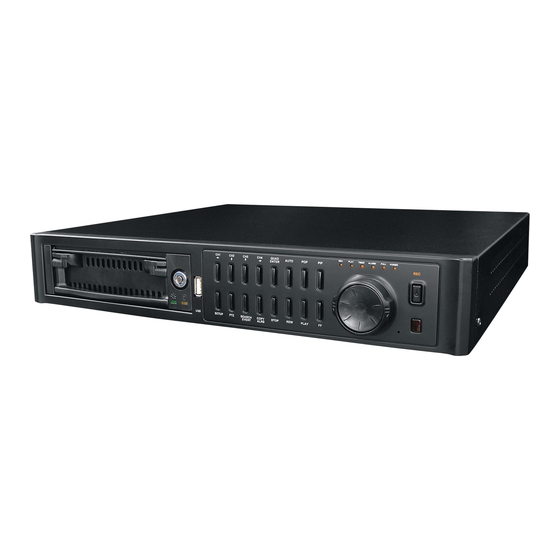
Page 10: Operation
3. OPERATION 3.1 FRONT PANEL PLAY TIMER ALARM FULL POWER QUAD AUTO ENTER ZOOM SETUP SEARCH BACKUP STOP PLAY ALRST SYS LOG WTMK PAUSE 1. HDD RACK Master HDD: Installed 160GB 2. CH 1 / LEFT - While in Quad mode, press this button momentarily (at least 3 seconds) and channel 1 will appear in full screen. - Page 11 4. CH 3 /DOWN - While in Quad mode, press this button momentarily (at least 3 seconds) and channel 3 will appear in full screen. - In full screen mode, channel 3 single screen or on PIP / POP / QUAD screen, press this button once and the screen will freeze.
- Page 12 10. LED - REC : The LED will blink when the system is in the recording mode. FUNCTION - PLAY : The LED will blink when the system is in the replaying mode. - TIMER : When the SCHEDULE RECORD is set, the LED will blink before it starts RECORDING.
- Page 13 WATERMARK CHECK - Press and hold this button for about 3 seconds in the playback mode, the Water Mark OSD will be shown on the screen. To exit, press and hold this button again for about 3 seconds. - The WTMK function : Watermarking is an identification code or bit pattern integrated into the multimedia data to aid copyright owners to identify illegally distributed video, or image data.
-
Page 14: Back Panel
CLOVER AC INPUT ELECTRONICS U.S.A MODEL NO : CDR4170 US LITED AC100-240V,50/60Hz, 25W E233232 AUDIO/VIDEO EQUIPMENT 2UW2 CLOVER ELECTRONICS RS485 POWER 13073 EAST 166TH STREET, CERRITOS, CA 90703 ETHERNET Factory ID/DHHS CODE : BC CAUTION ATTENTION RISK OF ELECTRONIC SHOCK... -
Page 15: Basic Configuration Of The Monitor Screen
4. BASIC CONFIGURATION OF THE MONITOR SCREEN 4.1 START UP When the system starts up, the following pictures will be displayed in sequence. Function Title Operational information Firmware version # Hard Drive information. Network Configuration - 10 -... -
Page 16: Live Screen
4.2 LIVE SCREEN Indicates recording HDD Camera Title Time and Date Full Screen in Live Mode Indicates recording HDD Camera Title Time and Date Quad Screen in Live Mode Indicates recording HDD Camera Title Time and Date PIP Screen in Live Mode - 11 -... -
Page 17: Recording Screen
Indicates recording HDD Camera Title Time and Date POP Screen in Live Mode 4.3 RECORDING SCREEN Indicates recording HDD Recording Camera Title Time and Date Quad Screen in Record Mode - 12 -... -
Page 18: Playback Screen
4.4 PLAYBACK SCREEN Indicates recording HDD Playback OSD & Speed Camera Title Time and Date Full Screen in Playback Mode Indicates recording HDD Playback OSD & Speed Camera Title Time and Date Quad Screen in Playback Mode Indicates recording HDD Playback OSD &... -
Page 19: Record And Playback Screen
4.5 RECORD AND PLAYBACK SCREEN Indicates recording HDD REC, Playback OSD & Speed Camera Title Time and Date Quad Screen in Record and Playback Mode Indicates recording HDD REC, Playback OSD & Speed Camera Title Camera Title Time and Date Nine Screens in Record and Playback Mode - 14 -... -
Page 20: Live
4.6 LIVE Live means viewing the present video images from the cameras on the monitor. 4.6.1 Full Screen display Full screen display is possible in the Live mode or Record mode. Use channel selection button to choose a corresponding video input. Refer to 4.2 “Full Screen in LIVE Mode”... -
Page 21: Recording
- Press the same channel selection button to release the freeze function. Freeze symbol 4.6.7 OSD On / Off Available in the LIVE, RECORD or PLAYBACK mode. When the OSD button is pressed, all the texts except the REC and PB (PLAYBACK) OSD are cleared temporarily. -
Page 22: Palyback
The whole recording lists are updated hourly up to 1,000 lists on both Master and Slave. 4.7.3 Schedule recording Recording by scheduled time The time of record start and finish can be set to hour: minute. Refer to section 5.7.6 for more information. 4.7.4 ALARM recording When an alarm signal is received, the system begins to record automatically. - Page 23 4.8.3 Playback by the last recording list When the SEARCH button is pressed, the SEARCH/HDD SET menu appears on the screen. Select THE LAST RECORD LIST and press the ENTER button. It will replay from the beginning of the last recorded list. Press the ESC button to return to the SEARCH/HDD SET menu.
- Page 24 Set the TIME/DATE by using the UP/DOWN buttons for changing the values and use the LEFT/RIGHT buttons to move to next field. Press the ENTER button to search the recorded image. If the recorded image exists, it automatically plays data and if not, it returns to the LIVE mode. In order to pause during playing, press the PLAY button.
-
Page 25: Setup
5. SETUP 5.1 SETUP SCREEN TREE - 20 -... - Page 26 - 21 -...
- Page 27 - 22 -...
-
Page 28: How To Setup
5.2 HOW TO SET UP - Setup is possible in the LIVE mode and partly in the recording mode, not in the playback mode. - Press the SETUP button. - Choose a setup item by using the UP/DOWN buttons and press the ENTER button. - Choose the desired values with the ENTER button. -
Page 29: Motion
5.3.6 REC SPEED • Choose the REC SPEED in the ALARM OPTION menu by using the UP/DOWN buttons. • Choose one REC SPEED among 01, 02, 03, 05, 10, 15, 30 and 60 IPS by repeatedly pressing the ENTER button, if the REC RESOLUTION in the RECORD menu set to 720H or 360H. -
Page 30: System
5.4.4 AREA • Choose the AREA in the MOTION menu with the UP/DOWN buttons • Press the ENTER button to create the motion detection AREA. • Move the symbol “O” by using the UP / DOWN / LEFT / RIGHT buttons and select the area where you would like to create, and press the ENTER button. - Page 31 • To apply the setting, press the ENTER button. 5.5.1.3 DATE FORMAT • Choose the DATE FORMAT in the TIME /DATE SET menu with the UP/DOWN buttons. • Select the DATE FORMAT by pressing the ENTER button. There are three formats to display the time and date as follows. MM / DD / YYYY: For U.S.A.
- Page 32 by using the LEFT/RIGHT/ENTER button, it starts to formatting or select NO for going back to the previous mode. 5.5.2.3 HDD INFO • Choose the HDD INFO in the HARD DISK menu by using UP/DOWN buttons. • Select BYTE, PERCENTAGE or OFF by pressing the ENTER button. •...
- Page 33 5.5.6.1 IP MODE • Choose the IP MODE in the IP CONFIGURATION menu with the UP/DOWN buttons. • Choose DYNAMIC IP or STATIC IP by pressing the ENTER button. DYNAMIC IP: The IP is automatically allocated via router. Therefore the IP address, subnet mask and gateway address will be automatically allocated.
-
Page 34: Video
NOTE: - Router has to be set as a virtual server (or port forwarding) in order to utilize the DDNS service (See section 5.11 for more details). - Do not use the public port numbers. - Four Port numbers (in sequence) including the default port number should be forwarded. -
Page 35: Record
5.6.2 DWELL TIME • VIDEO Choose the DWELL TIME in the menu with the UP/DOWN buttons. • Press the ENTER button, and the DWELL TIME menu will be displayed. • Select the desired channel by using UP/DOWN buttons and press the ENTER button to change the dwell time of the desired channel. -
Page 36: Display
5.7.5 AUDIO REC • Choose the AUDIO REC in the RECORD menu by using UP/DOWN buttons. • Select ON or OFF by pressing the ENTER button. NOTE: The system does not record when the recording speed is set to less than 4 IPS. 5.7.6 SCHEDULE REC •... -
Page 37: Buzzer
At “ON” mode, the borderline will be shown on the screen. 5.8.3 TIME/DATE • Choose the TIME/DATE in the DISPLAY menu by using UP/DOWN buttons. • Select ON or OFF by pressing the ENTER button. At “ON” mode, the time/date will be shown on the screen. 5.8.4 POSITION •... - Page 38 5.10.1.1 PASSWORD • Select the PASSWORD in the DVR ACCOUNT menu by using UP/DOWN buttons. • Select ON or OFF by using the ENTER button. • If ON is selected, the password has to be entered to get into the following mode. Setup mode, Search mode, Record mode, Record stop mode, PTZ mode and System Log mode.
-
Page 39: Ddns
• Press the ENTER button and the NETWORK ACCOUNT menu will be displayed. 5.10.2.1 USER ID • Select the USER ID in the NETWORK ACCOUNT menu by using UP/DOWN buttons. • Press the ENTER button. • Change the values up to 5 digits with the UP/DOWN buttons and move the digits with the LEFT/RIGHT button. - Page 40 5.11.2 HOST NAME • Choose the HOST NAME in the DDNS SET menu with the UP/DOWN buttons. • Press the ENTER button to change the values with the UP/DOWN buttons and select the digits (up to 8 digits) by using the LEFT/RIGHT buttons. •...
-
Page 41: Install The Hdd
10. To complete, click Add Host on the bottom. 11. After registration, go to the DDNS SET menu on the DVR. 12. Refer to section 5.11 DDNS in this manual for the next step. Registration to CLOVERDVR.COM 1. Go to website www.cloverdvr.com 2. -
Page 42: Install The Hdd2
4. Attach the HDD to the removable HDD rack and secure it with the supplied screws as below. 5. Assemble and put the removable HDD rack back in it’s place. 6. Turn the power on and see if the HDD is being recognized. If the HDD is not recognized after installing, please check the HDD jumper setting, NOTE power cable and data cable connection. - Page 43 HDD2 ATTACHING POINT Be sure that the jumper setting is correct. If not, the system will not recognize the NOTE additional HDD (SLAVE). 4. Secure the HDD with the supplied screws as below. FIX SCREW 5. Connect the power connector and the flat cable to the HDD. Be sure that the power connector and the flat cable are properly connected.
-
Page 44: Ptz Control
7. PTZ CONTROL 1. Connect Pan/Tilt/Zoom camera’s control to RS485(+) / RS485(-) port on the rear of the system. 2. The video output of Pan/Tilt/Zoom camera to the one out of channel you wish to connect. 3. Press and hold the PTZ button for about 3 seconds on the front panel and the PAN/TILT CONTROL screen will be displayed on the monitor. -
Page 45: Installation
CLOVER AC INPUT ELECTRONICS U.S.A MODEL NO : CDR4170 US LITED AC100-240V,50/60Hz, 25W E233232 AUDIO/VIDEO EQUIPMENT 2UW2 CLOVER ELECTRONICS RS485 POWER 13073 EAST 166TH STREET, CERRITOS, CA 90703 Factory ID/DHHS CODE : BC ETHERNET CAUTION ATTENTION RISK OF ELECTRONIC SHOCK... -
Page 46: Camera
CLOVER AC INPUT ELECTRONICS U.S.A MODEL NO : CDR4170 AC100-240V,50/60Hz, 25W US LITED E233232 AUDIO/VIDEO EQUIPMENT 2UW2 CLOVER ELECTRONICS POWER RS485 13073 EAST 166TH STREET, CERRITOS, CA 90703 Factory ID/DHHS CODE : BC ETHERNET CAUTION ATTENTION RISK OF ELECTRONIC SHOCK... -
Page 47: Monitor
CLOVER AC INPUT ELECTRONICS U.S.A MODEL NO : CDR4170 US LITED AC100-240V,50/60Hz, 25W E233232 AUDIO/VIDEO EQUIPMENT 2UW2 CLOVER ELECTRONICS POWER RS485 13073 EAST 166TH STREET, CERRITOS, CA 90703 Factory ID/DHHS CODE : BC ETHERNET CAUTION ATTENTION RISK OF ELECTRONIC SHOCK... -
Page 48: Networking
CLOVER AC INPUT ELECTRONICS U.S.A MODEL NO : CDR4170 US LITED AC100-240V,50/60Hz, 25W E233232 AUDIO/VIDEO EQUIPMENT 2UW2 CLOVER ELECTRONICS POWER RS485 13073 EAST 166TH STREET, CERRITOS, CA 90703 Factory ID/DHHS CODE : BC ETHERNET CAUTION ATTENTION RISK OF ELECTRONIC SHOCK... -
Page 49: Connecting The Dvr Through Gui (Cldvr)
How to install the client program (CLDVR) 1. Start the operating system (Windows 98/2000/XP). 2. Insert the program CD into CD-ROM drive. 3. Open My Computer, and then select CD-ROM drive. 4. Select the CLDVR folder, and then double click SetupCLDVR.EXE. The software installation will begin. -
Page 50: Cldvr Screen
The following CONFIG screen will be shown. • Enter the IP/URL, Port number (default: 5700) and ID (default: admin), which must be the same as for DVR. NOTE: ■ If the registered Host Name is CLOVER11 at www.dyndns.org, enter clover11.dyndns.org in IP/URL. ■... -
Page 51: Explanation Of Cldvr Function
clover.cloverdvr.com 1. CONNECTION STATUS INDICATOR It indicates that is currently being connected IP address and bandwidth (transmission speed). 2. FUNCTION OF BUTTONS Refer to next section. 3. LED DISPLAY, CLOCK The LED is lit depends on mode such as LIVE, PLAYBACK and RECORD. And the clock indicates the present time. - Page 52 1. F/W (FIRMWARE) The FIRMWARE can be upgraded by pressing the F/W button or USB device. This button is not for users, only for manufacturers and distribution center. 2. SAVE • Click the SAVE button to save the video images that is currently being displayed on the GUI.
- Page 53 admin Select the HDD (Master or Slave) Select 1 out of the lists for setting up the Backup Start Time. Setup the Backup End Time and click on blank box. If the End Time is not selected, the BACKUP continues until the Playback automatically ends. Click the Play&Backup button, and data will be saved on the BACKUP folder.
- Page 54 Select Channel Reset button 7. PRINT • Click the PRINT button to print the current pictures shown on the GUI and then the following window pops up along with “WAIT…”. Please wait a couple of seconds until the system loads data to print. 8.
- Page 55 10. QUAD BUTTON • Click the Quad button to display the quadrant pictures. 11. AUTO BUTTON • The GUI will be viewed a full screen at a time in a continuous sequence (one camera after another) by clicking this button. •...
- Page 56 on the window and press the Update REC.Quality button to save them. • Installed HDD and Recording HDD: Shows currently installed HDD information such as connection information, whole capacity and used space. It shows currently being recorded HDD as well. Do not change the recording HDD as possible as you can. •...
- Page 57 1. Select HDD (Master/Slave) you wish to search. 2. Choose one of recording lists, which are updated hourly up to 1,000 lists on both Master and Slave. 3. Click the Play button to replay the selected list, or double click the selected list to replay.
- Page 58 16. REW • Press this button to rewind the recorded images. • The speed will be increased up to x16 speed when you keep clicking this button. • The speed is shown below the buttons. 17. PLAY Press this button to replay from the beginning of the first recording list on HDD. 18.
-
Page 59: Local Viewer
9.5.2 PTZ CONTROL The following picture enables you to control PTZ camera connected to the system. FOCUS control PAN control ZOOM control TILT control PAN/TILT CONTROL Press UP key for TILT UP, DOWN key for TILT DOWN, LEFT key for PAN LEFT and RIGHT key for PAN RIGHT. - Page 60 3. Click in the box of WATER MARK to put WATER MARK while replaying (See section 9.5.1 #14 setup for more details). 4. Select TV system between NTSC and PAL depending on the broadcasting system in your country (NTSC in USA). 5.
-
Page 61: Appendix
APPENDIX 1. RECORDING TIME TABLE (DAYS) 1.1 REC RESOLUTION (720H) / REC QUALITY (VERY HIGH) SPEED 40G HDD 80G HDD 120G HDD 200G HDD 01 IPS 15-Days 19-Hours 31-Days 12-Hours 47-Days 07-Hours 78-Days 19-Hours 02 IPS 7-Days 22-Hours 15-Days 19-Hours 23-Days 17-Hours 39-Days 12-Hours 03 IPS... - Page 62 30 IPS 1-Days 00-Hours 2-Days 00-Hours 2-Days 22-Hours 4-Days 22-Hours 60 IPS 12-Hours 1-Days 00-Hours 1-Days 12-Hours 2-Days 12-Hours 1.5 REC RESOLUTION (360H) / REC QUALITY (VERY HIGH) SPEED 40G HDD 80G HDD 120G HDD 200G HDD 01 IPS 24-Days 22-Hours 49-Days 19-Hours 74-Days 14-Hours 124-Days 09-Hours...
-
Page 63: Factory Default Table
10 IPS 4-Days 17-Hours 9-Days 09-Hours 14-Days 02-Hours 23-Days 09-Hours 15 IPS 3-Days 02-Hours 6-Days 07-Hours 9-Days 09-Hours 15-Days 14-Hours 30 IPS 1-Days 14-Hours 3-Days 02-Hours 4-Days 17-Hours 7-Days 19-Hours 60 IPS 19-Hours 1-Days 12-Hours 2-Days 07-Hours 3-Days 22-Hours 1.9 REC RESOLUTION (CIF) / REC SPEED (120 IPS) QUALITY 40G HDD 80G HDD... - Page 64 [1-2] TIME : Time does not get initialization. [1-3] DATE FORM : MM/DD/YYYY [1-4] DATE : Date does not get initialization. [2] HARD DISK [2-1] HDD1 : Shows information on HDD that is connected to HDD1. [2-2] HDD1 : Shows information on HDD that is connected to HDD2. [2-3] HDD INFO : BYTE [3] FACTORY DEFAULT SETTING [4] SYSTEM INFORMATION : SYSTEM FIRMWARE VERSION...
-
Page 65: Faq
[6-1] SCHEDULE REC : OFF [6-2] SCHEDULE REC SETTING : No setup data 6] DISPLAY [1] TITLE DISPLAY : ON [2] BORDER LINE : ON [3] TIME / DATE : ON [4] POSITION : BOTTOM 7] BUZZER [1] KEY BUZZER : ON [2] VIDEO LOSS : ON 8] ACCOUNT [1] DVR ACCOUNT SET... - Page 66 - Check the brightness and contrast level of the monitor. 4. CHANNEL IS IN BLACK & WHITE MODE - Check the cameras. RECORDING RELATED PROBLEMS CORDING UNAVAILABLE - Adjust the camera screen. - Check recording speed or recording schedule. - Adjust the system. PLAY AND SEARCH RELATED PROBLEMS No Recorded Data.
-
Page 67: Limited 2Year Warranty
Limited 2Year Warranty This warranty gives the original purchaser specific legal rights and you may also have other rights, which may vary from state to state. If our products do not function because of any defect in material or workmanship, we will repair it for free for 2 year on parts and labor from the date of original purchase. This warranty does not cover modification, abuse, incidental or consequential damages unless the state of owner’s residence specially prohibits limitations on incidental or consequential damages.