
Related Manuals for Clover C1704DVR


Summary of Contents for Clover C1704DVR
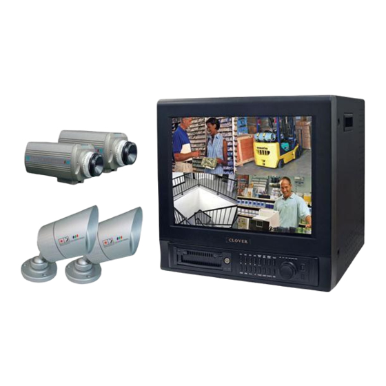
- Page 1 USER’S INSTRUCTIONS 17” COLOR MONITOR BUILT-IN 4CH DIGITAL VIDEO RECORDER MODEL C1704DVR...
-
Page 2: Table Of Contents
CONTENTS: System Specifications------------------------------------------------------------------------------------------- How to operate -------------------------------------------------------------------------------------------------- 2.1. General Information ------------------------------------------------------------------------------------ 2.2. Configuration of the front panel of the unit ---------------------------------------------------- 2.3. Configuration of the back panel of the unit ---------------------------------------------------- 2.4. Basic configuration of the monitor display ---------------------------------------------------- 2.5. Live --------------------------------------------------------------------------------------------------------- 2.6. - Page 3 3.7.4 Audio Level -------------------------------------------------------------------------------------- 3.8. Record ----------------------------------------------------------------------------------------------------- 3.8.1 Overwrite ----------------------------------------------------------------------------------------- 3.8.2 Power On Rec ----------------------------------------------------------------------------------- 3.8.3 Record --------------------------------------------------------------------------------------------- 3.8.4 Record Quality ---------------------------------------------------------------------------------- 3.8.5 IDSM* Sensitivity ------------------------------------------------------------------------------- 3.8.6 Motion Sensitivity ----------------------------------------------------------------------------- 3.8.7 Motion Hold -------------------------------------------------------------------------------------- 3.8.8 Record Speed ----------------------------------------------------------------------------------- 3.8.9 Record Schedule ------------------------------------------------------------------------------- Display ------------------------------------------------------------------------------------------------------ 3.9.1 Various Displays -------------------------------------------------------------------------------...
- Page 4 5.4.2 PRINT Button ------------------------------------------------------------------------------------ 5.4.3 System Status ----------------------------------------------------------------------------------- 5.4.4 Alarm, SEQ, OSD and Quad ---------------------------------------------------------------- 5.4.5 Channel Selection Button ------------------------------------------------------------------- 5.4.6 REC, SEARCH, STOP (ESC) and SETUP (ENTER) Button -------------------------- Camera Installation -------------------------------------------------------------------------------------------- Monitor and VCR Installation ------------------------------------------------------------------------------- Remote Control ------------------------------------------------------------------------------------------------- APPENDIX ------------------------------------------------------------------------------------------------------------------- Recording Time Table ----------------------------------------------------------------------------------------- Factory Default Table ------------------------------------------------------------------------------------------...
-
Page 5: System Specifications
Specifications Video Signal System NTSC or PAL (Auto Detection) Video Input 4 Camera Inputs (BNC or Mini Din) Basic Features Video Output 2 BNC Video Output for Slave Monitor or VCR Audio Input 4 Channel (Mini Din or RCA) Audio Output 2 Channel (VCR OUT / MONITOR OUT) Alarm Input 4 Alarm Inputs... - Page 6 User Input Device Front Panel keypad Timer Built-in real time clock [Fig 1-1. Specifications] MONITOR Picture Tube 17” Color Quad Screen Horizontal Resolution 420 Line at Center Camera Capable Up to 4 Input Signal Composite 1 Vp-p (V:0.714 Vp-p, Sync : 0.3 Vp-p) Monitor Power Consumption 105 Watts (Max.)
-
Page 7: How To Operate
How to operate General Information You can operate all functions of the system by use of the 18 buttons on the front of the unit. Additionally, you can remotely control this unit via the Ethernet port located on the back side. The system status is indicated by either with the LED light on the operator buttons or on the monitor. -
Page 8: Configuration Of The Back Panel Of The Unit
12) TIMER LED (Timer Recording Status Display LED) 26) MIC 13) ALARM LED (Alarm Status Display LED) 27) REMOTE CONTROL SENSOR 14) HDD FULL LED (HDD Status Display LED) ** By pressing and holding this button the user has the ability to talk to a specific camera location. This button must be pressed the entire time, while talking. -
Page 9: Basic Configuration Of The Monitor Display
Basic configuration of the monitor display Mode Remaining HDD Capacity Camera Title Date and Time [Fig. 2-2 Quad Display in Record Mode (4 equal split)] Playback position Mode Camera Title Date and Time [Fig. 2-3 Quad Display in Replay Mode (4 equal split)] - 8 -... - Page 10 Mode (RED) Remaining HDD Capacity Camera Title (RED) Date and Time [Fig. 2-4 Full Display in Record Mode] Playback position Mode (BLUE) Camera Title Date and Time (ORANGE) [Fig. 2-5 Full Display in Replay Mode] - 9 -...
- Page 11 Remaining HDD Capacity Camera Title (white) Date and Time [Fig. 2-6 Quad Display in Live Mode, Not in Record Mode] Remaining HDD Capacity Camera Title Date and Time [Fig. 2-7 Full Display in Live Mode, Not in Record Mode] When the user turns off the recording, the REC display on top left corner will be CAUTION disappeared.
-
Page 12: Live
Live Live means viewing the present video images from the cameras on the screen. LIVE MODE ► Full screen display Full display is possible in the Live mode or Record mode. Use channel selection button to choose a corresponding video input. ►... - Page 13 In the Quad mode - When the FREEZE button is pressed, all 4 displays are in freeze standby mode. - Press the FREEZE button again to release the freeze standby function of all the displays. ► OSD ON/OFF (OSD: On Screen Display) - Available in LIVE, RECORD, or REPLAY Mode.
-
Page 14: Recording
Recording Recording Option ► Manual recording ► Timer recording ► Alarm recording - Available in LIVE or RECORD mode Manual recording ► Recording will start when the REC button is pressed. The REC indicator will be lit and ‘REC’ will blink on the screen while the unit is recording. -
Page 15: Replaying
Replaying Replay Mode (Press PLAY button) ► Replaying from the first recording time ► Replaying from the last recording time ► Replaying from the set recording time. ► Replaying by event log lists. Replaying from the first recording time ► When the PLAY button is pressed, the SEARCH menu appears on the screen. - Page 16 ► Press DOWN button and select TIME & SEARCH menu. Press ENTER to select TIME & SEARCH menu. TIME & SEARCH menu appears on the screen. Replay Start Record Start Record Finish [Fig. 2-9 TIME & SEARCH MENU] ► THE FIRST RECORDED INFO displays beginning of the recording start time. THE LAST RECORDED INFO displays end of the recording finish time.
- Page 17 Screen selection in Replaying ► During replay, press the 1, 2, 3 or 4 button (channel selection button) to view only the corresponding video channel. ► Press the QUAD button to view the quad display. ► The OSD ON/OFF button functions during replaying as well. - 16 -...
-
Page 18: Setup
Setup Setup displays tree - 17 -... - Page 19 [Fig. 3-1 Setup Displays] - 18 -...
-
Page 20: How To Set Up [Model Number]
[Fig. 3-2 Setup Display] Alarm Setup Press the SETUP button on the front panel of C1704DVR. Press the ESC button to go back to the live mode. Choose ALARM SETUP by using the up/down navigation keys and press the ENTER button. The following menu will be displayed. -
Page 21: Alarm Hold & Buzzer Out
[Fig. 3-4 Alarm On/Off Display] - ALARM ON: The system will record when the alarm activates. Select ALRAM ON for alarm recording. 3.4.2 Alarm Hold & Buzzer Out ► ALARM HOLD Choose ALARM HOLD in the ALARM SETUP menu with the navigation keys and use the RIGHT/LEFT navigation buttons to change the time. -
Page 22: System
System [Fig. 3-6 System Display] Choose SYSTEM in the SETUP menu with the navigation buttons and press the ENTER button. This setup is very important and has to be made before starting the system. 3.5.1 Time / Date [Fig. 3-7 Time/Date Display] ►... -
Page 23: Hard Disk
view the images later. Changing time and date can cause the DVR to work improperly when you try to playback video. Care should be taken not to change the time after the initial setup unless absolutely necessary, as it may result in loss of recorded data. The HDD has to be formatted after changing the time. - Page 24 [Fig. 3-10 HDD Formatting Process 2] [Fig. 3-11 HDD Formatting Process 3] Press the ESC button to return after formatting is completed. ► HDD INFO Choose HDD INFO in the HARD DISK menu with the navigation keys and press ENTER button. [Fig.
-
Page 25: System Information
Be sure that the jumper setting is master position on the HDD. If not, the system will not recognize the HDD. Format it to record (See page 22 for more details). 3.5.3 System Information [Fig. 3-13 System Information Display] ► Choose SYSTEM INFO in the SYSTEM menu with the navigation keys and press ENTER button. 3.5.4 Factory Default ►... - Page 26 [Fig. 3-16 Factory Default Process 3] [Fig. 3-17 Factory Default Process 4] ► Press the ESC button to return after FACTORU DEFAULT is completed. User must aware that FACTORY DEFAULT deletes all system logs. CAUTION - 25 -...
-
Page 27: Network Ip Configuration
3.5.5 Network IP Configuration [Fig. 3-18 Network IP Configuration Setup] Choose NETWORK IP CONFIG in the SYSTEM menu with the navigation keys and press ENTER button. Choose IP SETUP in the NETWORK IP CONFIG menu with the navigation keys and press ENTER button. -
Page 28: Ddns
► GATEWAY / SUBNETMASK Choose the item and press the ENTER button. Set the value using the navigation keys: UP/DOWN keys for changing the value and LEFT/RIGHT keys for changing the position. Press ENTER to save the changes. ► PORT The PORT is the TCP address of the program which is used to connect to the network viewer and has a range of 2500 ~ 2509. - Page 29 with a dynamic IP address cannot provide various Internet services such as running a homepage. At the time of writing, user can select one of four DDNS service provider. If you are using dynamic IP, please select one from your providers and sign up. ►...
-
Page 30: Log Information
3.5.7 Log Information [Fig. 3-21 Log Information Display] Choose the SYSTEM LOG in the LOG INFORMATION menu and press ENTER button to replay. Press ESC button to return to the LOG INFORMATION menu. ► LOG INFORMATION screen displays a record of various events logged by the DVR. The list shows the dates and times when the event occurs. -
Page 31: Video
Video [Fig. 3-22 Video Setup Display] Choose VIDEO in the SETUP menu with the navigation buttons and press the ENTER button. 3.6.1 Camera Titles [Fig. 3-23 Camera Titles Display] ► Choose CAMERA TITLES in the VIDEO SETUP menu with the navigation keys and press the ENTER button. -
Page 32: Brightness
3.6.3 Brightness [Fig. 3-24 Brightness Setup Display] ► Choose BRIGHTNESS in the VIDEO SETUP menu with the navigation keys and press the ENTER button to adjust the brightness of each channel. ► Use the LEFT/RIGHT buttons to move to the next field and use the UP/DOWN buttons to select correct brightness level. -
Page 33: Audio
Audio [Fig. 3-26 Audio Setup Display] 3.7.1 Audio Record ► Choose AUDIO RECORD in the AUDIO SETUP menu with the navigation keys and press the LEFT/RIGHT button to turn on/off the audio recording. ► Press ENTER button to save the changes. The DVR does not record audio when the recording speed is set to less 4 FPS. -
Page 34: Record
Record [Fig. 3-27 Record Setup Display] Record setup is mostly related with image quality and the recording time and it has to be set before starting to use the unit for the first time. Choose RECORD in the SETUP menu with the navigation buttons and press the ENTER button. Choose the channel to modify the setting. -
Page 35: Record Quality
3.8.4 Record Quality ► Select the channel and press the ENTER button. Choose RECORD QUALITY in the RECORD CHANNEL SETUP menu with the navigation keys. Select a quality level among VERY HIGH, HIGH, STANDARD and LOW. Press the ENTER button to save the changes. For the same recording quality, frame size will vary according to various reasons such as recording picture quality setting, movement, complexity of the image and CAUTION... -
Page 36: Motion Hold
3.8.7 Motion Hold ► Select the channel and press the ENTER button. Choose MOTION HOLD in the RECORD menu with the navigation keys and press the ENTER button. Select a motion hold time (in seconds) and press the ENTER to save the changes. Sensor-on Time HOLD Time Recording Time... -
Page 37: Record Speed
3.8.8 Record Speed ► Select the channel and press the ENTER button. Choose RECORD SPEED in the RECORD menu with the navigation keys and press the ENTER button. Select a speed rate between 1~30 FPS for NTSC, and 1~25 FPS for PAL. 3.8.9 Record Schedule ►... -
Page 38: Display
Display [Fig. 3-28 Display Setup] Choose DISPLAY in the SETUP menu with the navigation buttons and press the ENTER button. 3.9.1 Various Displays ► Time Display: Choose TIME DISPLAY in the DISPLAY SETUP menu with the navigation keys and select ON and OFF with the navigation keys and press the ENTER button. The present time is shown on the monitor in ON mode. -
Page 39: 3.10 Account
BRIGHT: Changes the brightness of the picture. COLOR: Changes the color of the picture. TINT: Changes the tint of the picture. SHARPNESS: Change the sharpness of the picture. 3.10 Account [Fig. 3-29 Account] Choose ACCOUNT in the SETUP menu with the navigation buttons and press the ENTER button. 3.10.1 Device ID &... - Page 40 ► Enter the new password with the 1, 2, 3 and 4 buttons. The password must have 8 digits. Press the ENTER button to continue the procedure. Enter the same password again to verify the password and press the ENTER button to set the new password. Care should be taken as the password will be changed by this procedure.
-
Page 41: Networking
2. Connection Via hub or router: Direct cable IP address or ID and Password of DDNS Client Program (Supplied with C1704DVR) Installing the program to the PC Install the program on the PC by using the program CD (supplied) as follows. -
Page 42: Connection And Setting
Connection and Setting In order to use remote viewing by DvrAdmin software, you will need to setup the following four operations. If you use Static IP, you only need to set the configuration of the software. Please follow the instruction. ►... -
Page 43: Dvradmin Setup
[Fig. 4-2 Port Forwarding Example] 4.4.2 DvrAdmin Setup ► Double click the DvrAdmin icon on the desktop to start the program. ► Click the CONFIG button on the GUI. [Fig. 4-3 Config Button] ► Enter the IP Address, PORT Number, ID and PASSWORD then click OK. If you set and sign up the DDNS, you may put the Domain Name instead of the IP address. -
Page 44: How To Use Dvradmin
How to use DvrAdmin Connect Once you put the right IP address, PORT number, ID and PASSWORD, click CONN button to display the images as in Fig. 5-1 below. [Fig. 5-1 Connection Button and Quad Pictures in Live Mode] You can exit the program at any time, by clicking the POWER button on the GUI. Live and Playback 5.2.1 Live Mode... - Page 45 (2) When you click the REC BAR (RECORDING STATUS BAR) button, you can see additional information of the recorded images under the search bar. Additional information shown under the search bar is RECORD START TIME, REQUEST TIME and RECORD LAST TIME.
-
Page 46: Save
Save 5.3.1 Still Image Save (BMP File Save) ► Select a channel and click the BMP button to start saving to save the image in BMP file format. You can only save the selected channel. [Fig. 5-5 BMP Button] ► Once you click the BMP button, the program will save every frame in BMP file format until you click the button again. -
Page 47: Video File Save (Avi File Save)
5.3.2 Video File Save (AVI File Save) ► Select the channel that you want to save. The program can only save one selected channel. [Fig. 5-8 AVI Button] ► The AVI button will be activated when you select a channel. Click the AVI button on the GUI. Enter the file name and select a folder that you want to save in. -
Page 48: Function Of The Buttons
Function of the buttons 5.4.1 INFO Button ► Click INFO button to upgrade the system firmware through network. You will need a BIN file to upgrade the DVR. [Fig. 5-11 INFO Button and Upgrade Display] ► To upgrade, click BROWSE and select the BIN file. And the system will start the upgrade process automatically. -
Page 49: System Status
5.4.3 System Status ► System status shows you the status of the program and the DVR. ► LIVE: This means that the program is showing the live screen. ► RECORD: This means that the DVR is recording. ► REPLAY: This shows you that the program is replaying the recorded image. ►... -
Page 50: Channel Selection Button
5.4.5 Channel Selection Button [Fig. 5-16 Channel Selection Button] ► User can see a channel in full screen by clicking one of the channel selection button. ► You can also use these buttons to navigate the SEARCH and SETUP menu. 5.4.6 SEARCH, STOP (ESC) and ENTER Button [Fig. -
Page 51: Camera Installation
Camera Installation - 50 -... -
Page 52: Monitor And Vcr Installation
Monitor and VCR Installation VIDEO INPUT AUDIO INPUT ETHERNET WARNING OUT VIDEO AUDIO VIDEO AUDIO RS-485 TRIGGER OUT VCR OUT MONITOR OUT VIDEO INPUT AUDIO INPUT AUDIO INPUT VIDEO INPUT MONITOR - 51 -... -
Page 53: Remote Control
Remote Control Stand-By Stand-By Mode On/Off. SETUP SETUP Brings up the Setup Menu. Select individual camera 1. Select individual camera 2. Select individual camera 3. Select individual camera 4. A-SEL Selects the Audio channel in Quad mode. A-SEL FREEZE FREEZE Freezes the Channel ARROW Arrow keys... -
Page 54: Appendix
APPENDIX Recording Time Table Quality Very High HDD capacity (GB) 1fps (days) 4fps (days) 8fps (days) 16fps (days) 30fps (days) 13.2 26.5 39.7 66.1 16.5 Quality High HDD capacity (GB) 1fps (days) 4fps (days) 8fps (days) 16fps (days) 30fps (days) 19.3 38.6 57.9... -
Page 55: Factory Default Table
Factory Default Table 1] ALARM [1] ALARM ON/OFF - CAMERA 1 ALARM 1: OFF - CAMERA 2 ALARM 2: OFF - CAMERA 3 ALARM 3: OFF - CAMERA 4 ALARM 4: OFF - POSTALARM: OFF [2] VIDEO LOSS ALARM - CAMERA 1 ALARM: ON - CAMERA 2 ALARM: ON - CAMERA 3 ALARM: ON - CAMERA 4 ALARM: ON... - Page 56 - GATEWAY: 192.168.001.001 - PORT: 2505 - DHCP: DISABLE -MAC ADDR: UNIQUE ID ON NETWORK [UNCHANGABLE] - DDNS SETUP - ID: DVR - PASSWORD: DVR - PROVIDER: no use [6] LOG INFORMATION 3] VIDEO [1] CAMERA TITLES - CAMERA 1: CAM1 - CAMERA 2: CAM2 - CAMERA 3: CAM3 - CAMERA 4: CAM4...
- Page 57 [3] AUDIO DISPLAY: ON [4] HDD CAPACITY: ON [5] BORDER LINE: GRAY [6] IDSM DISPLAY: OFF 8] ACCOUNT [1] DEVICE ID: CLOVER [2] USER ID: Admin [3] PASSWORD - PASSWORD: OFF - NEW PASSWORD [SET YOUR PASSWORD (DEFAULT PASSWORD IS 11111111]...
-
Page 58: Faq
Entire Screen Problem • MONITOR IS NOT WORKING - Check the monitor power. - In case of no problem is discovered from above checks, replace monitor if monitor is bad. • MONITOR SCREEN IS NOT GOOD, FLICKERING AND BLURING - Adjust monitor setting. - Check the cameras and avoid the strong spot light and sunlight . - Page 59 • TOO SHORT STORAGE PERIOD - No Motion Sensitivity or IDSM mode setting made. - Adjust recording frame or recording schedule. - Adjust alarm recording. - Check the camera input. • RECORDING UNAVAILABLE - Check if camera input works properly from surveillance screen. If there is no input, recording does not function.
-
Page 60: Limited 2 Year Warranty
• BEEP SOUND DURING STARTUP - Check the Video Loss Alarm and status of the alarm system. - Check the system version and ask your supplier. - In case of no problem is discovered from the above checks, contact your supplier. •...