Table of Contents
Advertisement
Quick Links
Advertisement
Table of Contents

Related Manuals for Clover CDR-1610


Summary of Contents for Clover CDR-1610
-
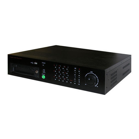
Page 1: Digital Video Recorder
USER’S MANUAL Stand-Alone 16channel DIGITAL VIDEO RECORDER MODEL CDR1610... - Page 2 CAUTION RISK OF ELECTRONIC SHOCK DO NOT OPEN CAUTION: TO REDUCE THE RISK OF ELECTRONIC SHOCK, DO NOT REMOVE COVER (OR BACK). NO USER SERVICEABLE PARTS INSIDE. REFER SERVICING TO QUALIFIED SERVICE PERSONNEL. Graphic Symbol Explanation This symbol is intended to alert the user to the presence of important operating and maintenance (servicing) instructions in the literature accompanying the product.
-
Page 3: Important Safeguards And Warnings
IMPORTANT SAFEGUARDS AND WARNINGS 1. Read Owner’s Manual 10. Lightning All the safety and operating instructions should be For added protection for this product during a read before this product is operated. lightning storm, or when it is left unattended and unused for long periods of time, unplug it from the 2. -
Page 4: Table Of Contents
Table of Contents Chapter 1: Introduction ■ …….………………..………………………………….. Technical Specifications..……….……………………………………………………. Installation………………………………….……………………………………….. Chapter 2: Operation Mode …….…….…….…………………………………. 13 ■ General Information…………………………………………………………………... 14 Power On/Off………………………………………………………………………….. 14 Display Screen……………………………………………………………………….. 15 System Status………………………………………………………………………….. 21 PTZ Control………………………………………………………………………….. How to Record…………………………………………………………………….. How to Replay ……………………………………………………………………….. 25 How to Backup ……………………………………………………………………….. -
Page 5: Chapter 1: Introduction
Chapter Introduction ■ Technical Specifications ■ Installation - 5 -... -
Page 6: Technical Specifications
1.1 Technical Specifications ■ CDR1610 (16ch DVR) ITEM DESCRIPTION SYSTEM System Control Front Keypad, Jog Shuttle, Mouse (PS2), IR Remote Controller Operating System (O/S) RTOS in Firmware Operating Help Support Instant OSD Language English, Chinese, Japanese, Korean VIDEO Video Format NTSC/PAL Video Inputs 16 Channels (BNC) -
Page 7: Installation
1.2 Installation ■ Package Contents • Digital Video Recorder • AC Power Cord • Remote Controller • Mouse (P/S-2) • Rack Mount bracket and bolts • Remote Client Software (CD-ROM) • User’s Manual ■ Installation Steps • Connect the cameras, the DVR unit and monitor (Refer to [Fig 5-3]). •... - Page 8 ■ Video Channel & Split Button Figure 1-2: Video Channel & Split Button Figure 1-2 1. No.1 Channel (Full Screen), 4A(Split Screen) 2. No.2 Channel (Full Screen), 4B(Split Screen), Up Key 3. No.3 Channel (Full Screen), 4C(Split Screen) 4. No.4 Channel (Full Screen), 4D(Split Screen) 5.
- Page 9 ■ Rear Panel Figure 1-4: Rear Panel Figure 1-4 1. Camera Input & Loop Output 2. Main Monitor 3. Power Input 4. VGA Monitor 5. S-VHS Monitor 6. Ethernet Port 7. RS-485 Port 8. Sensor Alarm Input 9. Control Relay Output 10.
- Page 10 ■ Monitor Connection 1. Main Monitor Connect the monitor to "Main" on the upper part of BNC connector. 2. S-VHS Monitor Connect the S-VHS monitor to "S-VHS" DIN jack on the rear of the unit. Output for S-VHS monitor is the same as that of main or auxiliary and has a separate output buffer and works independently.
- Page 11 ■ RS-485 Connection Using the RS-485 Terminal Block you can connect to the RS-485 cable up to 1 Km. Figure 1-8: RS-485 connection for PTZ camera ■ Ethernet Connection Ethernet connector is a RJ45 type. The maximum cable length is 100m. When you would like to use a longer cable, you cane use repeater.
- Page 12 ■ Power Cable Connection Input the power after selecting power voltage of back side of system. Input voltage tolerance is 10% and we can not warranty if you are using the over tolerance around 10%. If the electric system is not stable, please using the UPS or AVR. Standard Input voltage: AC110V 50/60Hz or AC220V 50/60Hz Figure 1-10: Input power selection CAUTION: FACTORY DEFAULT SETTING IS AC110V 50/60Hz IN POWER...
-
Page 13: Chapter 2: Operation Mode
Chapter Operation Mode General Information ■ Power On/Off ■ Display Screen ■ System Status ■ PTZ Control ■ How to Record ■ How to Replay ■ How to Backup ■ - 13 -... -
Page 14: General Information
2.1 General Information You can operate all functions of the system by use of the 26 buttons located on the front panel and a mouse. Also you can remotely control this unit via RS-485 or the Ethernet port located on the backside. System status is indicated by either LED light on the operator buttons or the monitor. -
Page 15: Display Screen
2.3 Display Screen ■ Camera View Figure 2-2: Full screen Figure 2-2 1. Status Icon: Record, Backup, Motion or Freeze, Sensor 2. Camera Name 3. Current Time ■ Screen Division 4A~4D Split screen 5 Split screen 8 Split screen 9 Split screen 10 Split screen 13A Split screen 13B Split screen... - Page 16 ■ Live Main Window ▪ Press the “MAIN” button or Click the mouse’s right button on the live screen. ▪ It will show the Live Main Window. ▪ Click the “EXIT” button, and it will return to the Live Screen. Figure 2-3: Live Main Window ■...
-
Page 17: Split Screen
■ Split Screen ▪ Split screen is possible in the LIVE mode or RECORD mode. ▪ Click the “SPLIT” button, and choose the desired split screen with the mouse’s wheel or “UP/DOWN” button. To complete the setting and close the Live Main Window, click the “SPLIT”... - Page 18 ■ Sequential Screen ▪ Sequential screen is possible in the LIVE mode or RECORD mode. ▪ Display each channel in turn after setting auto switching of video input channel. ▪ To display the sequential screen and close the LIVE MAIN Window, press the “SEQUENCE”...
- Page 19 Figure 2-9: Zooming screen ▪ ZOOM IN: Click the ‘+’ button or Press “UP/DOWN/LEFT/RIGHT” button on the front panel. ▪ ZOOM OUT: Click the ‘-’ button or Press “UP/DOWN/LEFT/RIGHT” button on the front panel. ▪ MOVE: Click the ‘Arrow’ button or press UP/DOWN/LEFT/RIGHT” button on the Front panel to move each direction of Zoom screen.
- Page 20 ■ Camera/VGA Enhance ▪ Click the “CAM/VGA ENHANCE” button on the Live Main Window, and then select the Camera enhance or VGA enhance by using mouse’s wheel or “UP/DOWN” button on the front panel. ▪ Select the channel to set Contrast / Brightness for camera or Contrast / Brightness / Saturation for VGA by using the mouse or the “UP/ DOWN/LEFT/RIGHT”...
-
Page 21: System Status
2.4 System Status ▪ Click the “SYS STATUS” button on the Live Main Window, and it will show the SYSTEM STATUS Window. Click the “EXIT (X)” button to return to the Live Main Window. Figure 2-13: System Status button ▪ System Status Window indicates a several options such as value of MAC address, IP address, Port number and the quantity of used HDD. - Page 22 ▪ Click the “VIDEO LOSS LISTS” button on the SYSTEM STATUS Window, and it will show the Video Loss Lists Window. ▪ Video Loss Lists indicate the Video Loss channel and time when the video is not inputted. ▪ It is able to indicate on unit of page in order with “UP/DOWN” button on the front panel or mouse’s wheel.
-
Page 23: Ptz Control
2.5 PTZ Control ▪ Click the “PAN/TILT” button on the Live Main Window, and it will show the PAN/TILT Window. Click the “EXIT (X)” button to return to the Live Main Window. Figure 2-17: PAN/TILT button ■ Full/Split/ID ▪ Select the Full/Split/ID button with the mouse or “UP/LEFT/ RIGHT/DOWN” button on the front panel, and then press the mouse’s left button or “ENTER”... -
Page 24: How To Record
2.6 How to Record ▪ You need to select a recording mode on RECORD CONFIG in advance. ▪ There are several recording options such as Manual Always Recording, Motion or Sensor Event Recording, Time & Day Schedule Recording. ▪ To start recording, click the “START RECOD” button on the Live Main Window. Figure 2-19: Start Record button Figure 2-20: Recording Status on Live Screen - 24 -... -
Page 25: How To Replay
2.7 How to Replay ▪ To replay the recorded data, click the “SEARCH” button on the Live Main Window, and it will show the SEARCH Window. Click the “EXIT (X)” button to return to the Live Main Window. Figure 2-21: Search menu ■... - Page 26 ■ Searching Time ▪ Select the searching time with the mouse or “UP/DOWN” button on the front panel. Figure 2-24: Record Play Window ▪ By clicking the “BAR” button under the menu of searching time, you can easily select the searching time from 1 to 10 stage of total recorded time.
- Page 27 ■ Start Replay ▪ Click the “REPLAY” button to replay the recorded data, and you can control replay speed 1 to 64 times. Figure 2-27: Start Replay buttons ■ Replay Control Buttons Figure 2-28: Replay Control buttons ▪ Pause Button To pause replaying, click the button or use the key Jog.
- Page 28 OSD(On Screen Display) On/Off ■ ▪ OSD On/Off is possible in the LIVE mode or RECORD mode. ▪ When the “OSD” button is clicked, all the texts except for the video display are deleted temporarily. ▪ When the button is clicked again while OSD is in OFF position, replaying screen will be the normal condition.
-
Page 29: How To Backup
2.8 How to Backup ▪ Backup function is only available on condition that the search path is set to “Record HDD”. ▪ In the SEARCH Window, select the backup list by clicking button. Once this button selected, it change to the checked sign button. - Page 30 ■ Backup USB Format ▪ Plug in USB stick memory on the front panel. ▪ When the USB memory is plugged into the system, the “GO TO BACKUP” button is activated and USB port LED is lighting on the front panel. ▪...
- Page 31 ■ Backup HDD Format ▪ To format the BACKUP HDD, you have to enable the backup HDD in System Configuration Window. ▪ Enter the Setup Window, select “SYSTEM” menu, and then select the “BACKUP DISK”. ▪ By using mouse’s wheel or “UP/DOWN” button on the front panel, set the backup disk to “ENABLE”.
- Page 32 ▪ If the backup HDD is installed for the first time in your system, it indicates “UNFORMATTED” on the DISK MANAGER Window. Figure 2-38: Unformatted Backup HDD ▪ Click the “HDD” button, and it will show the check message for HDD format. ▪...
- Page 33 ■ Starting Backup ▪ Select the backup disk, and then click “BACKUP START” button. Figure 2-40: Backup disk selection ▪ The backup icon will show on the left upper corner of the Live Screen. ▪ If the backup disk is selected as USB disk, the backup USB LED is twinkling during the backup process Figure 2-41: Backup process icon ■...
-
Page 34: Chapter 3: Setup Mode
Chapter Setup Mode Setup Window ■ System ■ Time / Date ■ Disk Manager ■ Camera ■ Record Configuration ■ Motion Configuration ■ Sensor Configuration ■ Network Configuration ■ Pan/Tilt Configuration ■ System Information ■ Color Setting ■ - 34 -... -
Page 35: Setup Window
3.1 Setup Window ▪ Press the “MAIN” button or Click the mouse’s right button on the live screen, and it will show the Live Main Window. ▪ Click the “SETUP” button, and it will show the Setup Window. ▪ Click the “EXIT” button, and it will return to the Live Main Window. Figure 3-1: Setup Window 3.2 System ▪... - Page 36 ■ Language ▪ You can select one of Language such as English, Japanese, Chinese and Korean. ▪ Select one of Language by using the mouse’s wheel or pressing the “UP/DOWN” key on the front panel. ▪ After selection, click the “LANGUAGE” button again for confirmation. Figure 3-3: Language Selection ▪...
-
Page 37: Mouse Sensitivity
■ Mouse Sensitivity ▪ It enables you to set the mouse sensitivity. It has parameter 1 to 4. ▪ Take a few second for the mouse initialize with changed parameter. Figure 3-6: Mouse Sensitivity Setting ■ Record Resolution ▪ Click “STOP RECORD” in the MAIN menu before setting the Record Resolution. ▪... -
Page 38: Firmware Update
■ Firmware Update THIS SECTION IS NOT FOR USERS, ONLY FOR MANUFACTURER AND DISTRIBUTION CENTER. [Update by LAN connection] ▪ If you want firmware update by using LAN connection, you should select “LAN ENABLE”. ▪ For more details, please refer to the Chapter 5 “Remote Host Software”. Figure 3-10: Firmware update via LAN [Update by USB device] ▪... - Page 39 [User ID Setting] ▪ Click the “USER ID” button, it will show On Screen Keyboard. ▪ Enter the user ID by using On Screen Keyboard, and then click “OK” button to set the new user ID. ▪ Click the “CANCEL” button to return to the user ID setting. Figure 3-13: User ID Setting [Password Setting] ▪...
-
Page 40: Time / Date
3.3 Time / Date ▪ Click the “TIME / DATE” button on the Setup Window, it will show the Time / Date Setup Window. ▪ Click the “EXIT” button on the Time / Date Setup Window, it will return to the Setup Window. -
Page 41: Date Format
■ Date Format ▪ Click the “DATE FORMAT” button, and then set the Date Format by using the mouse wheel or “UP/DOWN” key on the front panel. ▪ It has three type of Date Format such as YYYY/MM/DD, DD/MM/YYYY, MM/DD/YYYY. Figure 3-17: Date Format ■... -
Page 42: Disk Manager
3.4 Disk Manager ▪ Click the “Disk Manager” button on the Setup Window, it will show the Disk Manager Setup Window. ▪ Click the “EXIT” button on the Disk Manager Window, it will return to the Setup Window. ▪ Total 4 HDDs can be installed and disk information will display automatically on the window after connected. -
Page 43: Camera
3.5 Camera ▪ Click the “CAMERA” button on the Setup Window, it will show the Camera Setup Window. ▪ Click the “EXIT” button on the Camera Setup Window, it will return to the Setup Window. Figure 3-22: Camera Setup Window ■... -
Page 44: Camera Title
■ Relay-out On/Off ▪ It enables you to activate relay-out when the video lost. ▪ There are six types of relay-out such as “X (off)”, “1”, “2”, “3”, “4”, “A”. ▪ You can select “ON” or “OFF” by using the mouse wheel or “UP/DOWN” key on the front panel. -
Page 45: Record Configuration
3.6 Record Configuration ▪ Click “STOP RECORD” in the MAIN menu before setting the Record Configuration. ▪ Click the “RECORD CFG” button on the Setup Window, it will show the Record Configuration Window. ▪ Click the “EXIT” button on the Record Configuration Window, it will return to the Setup Window. - Page 46 ■ Manual Record Mode Setting ▪ In the Manual Record Mode, the recording works only by user’s operation. Figure 3-30: Manual Record Mode Setting [Quality Setting] ▪ Click the “QUALITY” button, you can see the live image and recording image at the same time on the split window.
- Page 47 [Cam Set] ▪ It enables you to set the recording speed of each camera. ▪ Click the “CAM SET” button on the Record Configuration Window, it will show the Recording Speed Setup Window. Figure 3-32: Recording Speed Setting Figure 3-32 1.
- Page 48 ▪ The Equal recording speed for all cameras 720 x 240 320 x 240 NTSC NTSC Total Each Total Each Total Each Total Each 3.75 3.12 7.50 6.25 1.87 1.56 3.75 3.12 0.93 12.5 0.78 1.87 1.56 ▪ The recording speed for each camera NTSC 0.50 0.50...
- Page 49 ■ Schedule Record Mode Setting ▪ In the Schedule Record Mode, the recording works according to time schedule. It will be automatically started and stopped. Figure 3-34: Schedule Record Mode Setting [Weekday / Saturday / Sunday] ▪ Click the “WEEKDAY / SATURDAY / SUNDAY” button, it will show time and recording parameter setting window.
- Page 50 [Specific Days] ▪ Click the “SPECIFIC DAYS” button, it will show the Specific Days Setting Window. ▪ Click the “EXIT button, it will return to the Record Configuration Window. Figure 3-36: Specific Days Setting - Specific Days List ▪ You can set the specific day up to 64 lists by using the mouse’s wheel or pressing the “UP/DOWN”...
-
Page 51: Motion Configuration
3.7 Motion Configuration ▪ Click the “MOTION CFG” button on the Setup Window, it will show the Motion Configuration Window. ▪ Click the “EXIT” button on the Motion Configuration Window, it will return to the Setup Window. Figure 3-37: Motion Configuration Window NOTE: MOTION CONFIGURATION IS ONLY AVAILABLE IN THE “STOP RECORD”... - Page 52 ■ Relay-out On/Off ▪ It enables you to activate relay-out when the motion is detected. ▪ There are six types of relay-out such as “X (off)”, “1”, “2”, “3”, “4”, “A”. ▪ You can select “ON” or “OFF” by using the mouse wheel or “UP/DOWN” key on the front panel.
- Page 53 [All Set / All Clear] ▪ Click the “ALL SET” button, you can create the motion detection area with a fully covered screen. ▪ Click the “ALL CLEAR” button to clear the motion detection area. Figure 3-43: All Set / Clear Setting [Window Set / Window Clear] ▪...
- Page 54 ■ Icon Display On/Off ▪ It enables you to display the motion icon on the Live Screen. ▪ You can select “ON” or “OFF” by mouse clicking or “UP/DOWN” key on the front panel. Figure 3-44: Icon Display On/Off Setting ■...
-
Page 55: Sensor Configuration
3.8 Sensor Configuration ▪ Click the “SENSOR CFG” button on the Setup Window, it will show the Sensor Configuration Window. ▪ Click the “EXIT” button on the Sensor Configuration Window, it will return to the Setup Window. Figure 3-49: Sensor Configuration Window ■... - Page 56 ■ Relay-out On/Off ▪ It enables you to activate relay-out when the sensor is detected. ▪ There are six types of relay-out such as “X (off)”, “1”, “2”, “3”, “4”, “A”. ▪ You can select “ON” or “OFF” by using the mouse wheel or “UP/DOWN” key on the front panel.
-
Page 57: Network Configuration
3.9 Network Configuration ▪ Click the “NETWORK CFG” button on the Setup Window, it will show the Network Configuration Window. ▪ Click the “EXIT” button on the Network Configuration Window, it will return to the Setup Window. Figure 3-54: Network Configuration Window ■... - Page 58 “UP/DOWN” key on the front panel. ■ Server THIS SERVER IS FOR DYNAMIC DOMAIN NAME SERVICE (DDNS), NOT AVAILABLE AT THIS TIME, BUT CLOVER WILL START THE SERVICE IN THE FUTURE. ▪ Click the “SERVER” button on the Network Configuration Window, it will show the Network Server Configuration Window.
-
Page 59: Pan/Tilt Configuration
3.10 Pan/Tilt Configuration ▪ Click the “PAN/TILT CFG” button on the Setup Window, it will show the Pan/Tilt Configuration Window. ▪ Click the “EXIT” button on the Pan/Tilt Configuration Window, it will return to the Setup Window. Figure 3-56: Pan/Tilt Configuration Window ■... -
Page 60: System Information
■ Data Bits ▪ The data bits types are 5~8 bits. ▪ Click “DATA BITS”, and then select the data bits by mouse wheel or “UP/DOWN” key on the front panel. ▪ Click the data bits again to confirm. Figure 3-60: Data Bits Selection ■... -
Page 61: Color Setting
3.12 Color Setting ▪ Click the “COLOR SET” button on the Setup Window, it will show the Color Setting Window. ▪ It enables you to adjust the color of GUI (Graphic User Interface) just as you want. ▪ The available clearance range are 0%, 50%, 75% and 100%. Lower level setting will increase clearance range. - Page 62 ■ Up Button Color ▪ Click “UP BUTTON COLOR”, and then select the up button color of Menu Button and clearance by mouse wheel or “UP/DOWN” key on the front panel. ▪ Click the color and clearance again to confirm. Figure 3-66: Up Button Color Setting ■...
-
Page 63: Chapter 4: Hdd Installation
Chapter HDD Installation General Information ■ How to Install ■ - 63 -... -
Page 64: General Information
4.1 General Information ▪ HDD is not included in the system as standard. ▪ Three of internal HDDs and one of removable HDD can be installed for the system. PAL/NTSC Selection Jumper Figure 4-1: System Arrangement Plan 4.2 How to install ▪... -
Page 65: Chapter 5: Remote Host Software
Chapter Remote Host Software Software Installation ■ Remote Host Screen ■ Backup Search ■ - 65 -... -
Page 66: Software Installation
5.1 Software Installation ▪ Start Windows 2000 or Windows XP. ▪ Insert the Remote Setup Program CD into the CD-ROM drive. ▪ Double-click SETUP.EXE. Now the installation will be started. ▪ After the installation has been completed, HOST icon will be created on your Desktop screen. - Page 67 ■ Connection Status Indicator ▪ It shows the connection status of remote host software and the current mode of DVR. Figure 5-3: Connected Figure 5-2: Disconnected Figure 5-4: DVR Live Mode Figure 5-5: DVR Record Mode Figure 5-6: DVR Search Mode Figure 5-7: DVR Setup Mode ■...
- Page 68 ① Model ▪ Select the type of DVR that you want to connect. ② Video Source ▪ Select the type of video source. ▪ After selection, you should exit and execute the remote host software again. ③ IP Table - Set Direct: Enter the IP address and Port number to connect to DVR directly. - Set Server: Enter the IP address and Port number of Mac Name Server.
-
Page 69: Backup Button
[With Get Server Setting] ▪ Enter the “Site Name” that is already registered in the DVR’s Network Server Configuration Window (See Section 3.9 “Network Configuration), and then click the “OK” button (This function is not available at this time). Enter Site Name Site Name List Figure 5-11: Site Name Input Window ■... - Page 70 ■ Print Button ▪ It enables you to print out the image that is displayed on the remote monitoring screen. ▪ It is only available in a full screen. ① ② Figure 5-13: Print Dialog Window ① Comment String ▪ It enables you to insert the comments on the printed image. ②...
-
Page 71: Ptz Control Buttons
■ Relay On/Off Buttons ▪ It enables you to activate relay output of DVR remotely. Figure 5-15: Relay On/Off Buttons ■ Buzzer On/Off Button ▪ It enables you to beep the buzzer of DVR remotely. Figure 5-16: Buzzer On/Off Button ■... - Page 72 ■ Record / Play Control Buttons Figure 5-20: Record / Play Control Buttons Play Control Button Record Start / End Button [Record Start / End Button] ▪ Click this button to save the image displayed on remote host screen. [Play Control Buttons] ▪...
-
Page 73: Backup Search
5.3 Backup Search ▪ When you click the Backup Search button (See figure 5-1: Remote Host Screen ④), it will show the Backup Search Window. Figure 5-23: Play List Window ■ Select Mode [Replay Backup File] ▪ Select the backup file, it will display backup image on the remote host screen. [Replay Backup File] ▪... - Page 74 ■ PC Backup Files ▪ It enables you to replay the backup file or convert it to AVI file. ▪ Click the PC Backup Files button, and then select the file that you want. Figure 5-25: Open Backup File Window ■...
-
Page 75: Appendix
Appendix 1. Recording Time Table ■ Capacity of 80GB HDD (NTSC) 30 fps 10 fps 5 fps 3 fps 2 fps 1 fps +SVHS (30G) 27 H 81 H 162 H 323 H 485 H 1131 H SVHS (15G) 37 H 111 H 222 H 444 H... - Page 76 ACTIVE ALL OFF TIMER RECORD TIMER ALL 00:00 ACTIVE ALL OFF BUZZER ALL OFF RELAY ALL OFF MOTION RECORD ALL OFF DETECT AREA ALL OFF DISPLAY HOLD TIME 1 SEC ACTIVE ALL ON BUZZER ALL ON ALARM RELAY ALL ON RECORD ALL ON HOLD TIME...
-
Page 77: Faq
■ I can’t Login! ▪ Please check if the link LED of DVR and LAN port of PC are lit. ▪ Please check if the IP address on DVR and the PC is identical. - Check the System Status by pressing OSD button of DVR. (Available on Live Mode and Record mode.) MY IP: xxx.xxx.xxx.xxx - Check the Target IP Address by clicking Conf button of PC host program. - Page 78 ■ Image is not being received! ▪ No image ( Image is not being received ) or image is blurred or distorted. - Modify Network Performance Values of DVR. (Menu – Setup – System – Network Performance ) [ In other type of network than specified below ] - Network Performance ⇒...
-
Page 79: Limited 2Year Warranty
■ LIMITED 2YEAR WARRANTY This warranty gives the original purchaser specific legal rights and you may also have other rights, which vary from state to state. If our products do not function because of any defect in material or workmanship, we will repair free for 2 year on parts and labor from the date of original purchase.