
Related Manuals for Clover CDR-0850


Summary of Contents for Clover CDR-0850
-
Page 1: Digital Video Recorder
Contents INSTRUCTION MANUAL Stand-Alone 8 Channel DIGITAL VIDEO RECORDER MODEL CDR0850 Copyright © 2007 Clover Electronics U.S.A. All Rights Reserved. -
Page 3: Table Of Contents
Contents CONTENTS ABOUT THIS MANUAL ..........................9 UNPACKING ............................11 DVR (D ..............12 TAND ALONE IGITAL IDEO ECORDER FEATURES............................13 WHAT TO DO AT THE TIME OF INSTALLATION ................15 SPECIFICATIONS..........................17 INSTALLATION ............................19 5-1. C & 16C DVR) ............20 ONTROLS AND ONNECTORS 5-2. - Page 4 Instruction Manual Stand-alone DVR 6-6.2. SPLIT SCREENS........................40 6-7. LIVE ............................ 41 6-7.1. FULL SCREEN ........................... 41 6-7.2. SPLIT SCREEN .......................... 41 6-7.3. SEQUENCING SCREENS......................42 6-7.4. LIVE AUDIO ..........................43 6-7.5. ZOOM ............................44 6-7.6. OSD ON / OFF..........................45 6-7.7.
- Page 5 Contents 7-2.1. TIME / DATE ..........................76 7-2.2. SYSTEM CONFIG ........................78 7-2.2.1. FACTORY DEFAULT ......................78 7-2.2.2. LOAD CONFIG / BACKUP CONFIG..................79 7-2.3. PASSWORD ..........................82 7-2.4. IR REMOTE ID ........................... 83 7-2.5. FIRMWARE UPDATE ......................... 84 7-2.6. SYSTEM INFO..........................84 7-3.
- Page 6 Instruction Manual Stand-alone DVR 7-6.8.2. Manual Event Recording....................105 7-6.8.3. Timer Recording (Schedule Recording) ................105 7-6.8.4. Timer Event Recording....................... 105 7-6.9. Recording by Motion Detection ....................106 7-6.10. Recording by Sensor (PIR Sensor)..................114 7-7. NETWORK........................117 7-7.1. IP Mode............................. 117 7-7.2.
- Page 7 Contents 9-2. I HDD.................. 151 NSTALLATION OF AN ADDITIONAL APPENDIX............................153 ......................154 ECORDING TIME TABLE ...................... 155 ACTORY DEFAULT SETTINGS FAQ ..............................159 ......................... 160 CANNOT LOGIN LIMITED 2YEAR WARRANTY ......................161 HOW TO OBTAIN FACTORY SERVICE ....................162...
- Page 8 Instruction Manual Stand-alone DVR...
-
Page 9: About This Manual
About this manual This is the Instruction Manual for Stand-alone type DVR model CDR0850. This Manual describes how to install and operate the Stand-Alone DVR and provides specifications and features. Please read this manual thoroughly and follow the installation process before using Stand- alone DVR (Note: Be sure to correctly follow step 3. - Page 10 Instruction Manual Stand-alone DVR...
-
Page 11: Unpacking
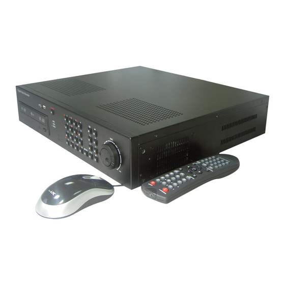
Unpacking Care should be taken when unpacking to avoid damaging the unit. Please check that the following items are included: ▶ Stand-alone DVR unit ▶ All Accessories : Bracket, Power Cable, Screws ▶ Remote Controller & Battery ▶ PS2 Mouse ▶... -
Page 12: Stand-Alone Dvr (Digital Video Recorder) Unit
Instruction Manual Stand-alone DVR Stand-alone DVR (Digital Video Recorder) Unit CDR0850 is the most reliable and functional embedded DVR system available today. The system displays 8 channels of live images in Real Time speed, compresses data digitally and records them to the Hard Disk Drive, which can be replayed and searched easily any time. The CDR0850 supports easy back up via USB port, DVD R/W, CD R/W and networking in both static &... -
Page 13: Features
Features ▶ Multi Functional Record -Powerful, multiple Record Modes available: Manual (Continuous), Timer, and Motion Detection Recording. ▶ User friendly GUI -A few simple buttons for Easy control. ▶ Automatic System Recovery -Automatic and Complete System recovery within 10 seconds. ▶Easy PTZ control via RS port -No need to use PTZ controller -PTZ control from remote PC... - Page 14 Instruction Manual Stand-alone DVR...
-
Page 15: What To Do At The Time Of Installation
What to do at the time of Installation Stand-alone DVR should be installed in the following order; 1. Make sure all the required hardware is available. Stand-alone DVR unit (including HDD) Up to 8 cameras (including power source) CCTV or VGA monitor (or TV set) Network cable if connecting to a PC 2. - Page 16 Instruction Manual Stand-alone DVR...
-
Page 17: Specifications
Specifications DESCRIPTIONS ITEM Television System NTSC Refresh Rate 60 fields/sec 50 fields/sec Video Resolution 720x480 720x576 8 Cameras VIDEO SIGNAL Video Inputs Composite 1.0 Vp-p 75 Ohms Video Input Signal 8 looping, Main monitor, Aux monitor, SVHS, VGA Video Outputs Composite 1.0 Vp-p 75 Ohms Video Output Signal Live... - Page 18 Instruction Manual Stand-alone DVR...
-
Page 19: Installation
Installation CONTENTS 5-1. C & 16C DVR) ............20 ONTROLS AND ONNECTORS 5-2. N ......................22 OTE FOR NSTALLATION 5-3. S ......................23 YSTEM ONNECTION 5-4. I ........................24 NSTALLATION 5-4.1. Camera Connection........................24 5-4.2. Monitor Connection........................24 5-4.3. Sensor Connection and RELAY IN &OUT .................. 26 5-4.4. -
Page 20: Controls And Connectors (For 8Ch & 16Ch Dvr)
Instruction Manual Stand-alone DVR 5-1. Controls and Connectors (For 8Ch & 16Ch DVR) Front POWER SHUTTLE DVD R/W HDD LED LINK LED DATA LED [Fig 5-1. Front View] IR Reciver 1 Channel(FULL Screen) 2 Channel(FULL Screen), UP Key 3 Channel(FULL Screen) 4 Channel(FULL Screen) 5 Channel(FULL Screen), LEFT Key 6 Channel(FULL Screen), ENTER Key... - Page 21 5. Installation a. Display (Full / Split) b. Emergency Record c. Zoom d. Quick Replay e. OSD On/Off Audio g. Stop (ESC) h. PTZ Rear VOLTAGE CAMERA POWER INLET LOOP OUT MAIN VIDEO AUX VIDEO MOUSE RS-422C PORT USB PORT ETHERNET SENSOR SPEAKER...
-
Page 22: Note For Installation
Instruction Manual Stand-alone DVR 5-2. Note for Installation Install the system according to the instructions described in this manual. This product is designed for indoor use and should not be used outdoors. Avoid any area with high humidity or dust which can shorten lifetime of the unit. Choose a well ventilated area and keep minimum of 10”... -
Page 23: System Connection
5. Installation 5-3. System Connection [Fig 5-3. System Connection]... -
Page 24: Installation
Instruction Manual Stand-alone DVR 5-4. Installation 5-4.1. Camera Connection ▫ Connection of Normal Cameras Connect the cameras to the Video Input (BNC connector) on the back of the unit as shown above [Fig. 5-3 System Connection]. ▫ Connection of Loop Output The Camera or video output is available from the Video Output (Loop Output) on the back of the unit. - Page 25 5. Installation ▫ VGA Monitor Connection Connect the VGA Monitor’s connector to the “DSUB 15 Pin Connector” on the rear of the unit. Output for VGA Monitor is the same as that of the main screen, however it outputs a better quality signal.
-
Page 26: 5-4.3. Sensor Connection And Relay In &Out
Instruction Manual Stand-alone DVR 5-4.3. Sensor Connection and RELAY IN &OUT ▫ SENSOR Connection (SENSOR IN) Connect the sensor to ALM (SENSOR) IN. The Sensor should be a contactor type and support NO (Normal Open). Refer to for connection. [Fig. 5-6 SENSOR IN/OUT PIN] [Fig 5-6. -
Page 27: 5-4.4. Rs232C Connection
5. Installation 5-4.4. RS232C Connection ▫ Connect the cable to the “RS232C PORT” on the rear of the unit. Specification of the RS232C connector is standard for “DSUB9” The Maximum Length of cable is 45 ft. When you want to use a longer distance, use “RS323 to RS422”... -
Page 28: 5-4.5 Connection To An Ethernet (Optional) Network
Instruction Manual Stand-alone DVR 5-4.5 Connection to an Ethernet (Optional) Network ▫ Connecting the cable to Ethernet. Our Ethernet connector is a RJ45 type. The maximum cable length is 300 ft. When you want to use a longer cable, we suggest using repeater. Refer to for connector pin configuration. -
Page 29: 5-4.6. Power Connection
5. Installation 5-4.6. POWER CONNECTION Select proper voltage (see fig 5-12) and connect to a reliable power source. It should not be shared with other electrical equipment on the same line. Poor performance can occur if the connected voltage is more than 10% plus or minus the required voltage. - Page 30 Instruction Manual Stand-alone DVR...
-
Page 31: How To Operate
How to operate CONTENTS 6-1. G ......................33 ENERAL NFORMATION 6-2. O ......................34 PERATING NTERFACE 6-3. IR R ......................35 EMOTE ONTROLLER 6-4. P ........................36 OWER 6-4.1. POWER ON..........................36 6-4.2. POWER OFF ..........................36 6-4.3. APPEARANCE OR DISAPPEARANCE OF POWER BUTTON..........37 6-5. - Page 32 Instruction Manual Stand-alone DVR CONTENTS 6-7. LIVE.............................41 6-7.1. FULL SCREEN ........................... 41 6-7.2. SPLIT SCREEN.......................... 41 6-7.3. SEQUENCING SCREENS ......................42 6-7.4. LIVE AUDIO..........................43 6-7.5. ZOOM............................44 6-7.6. OSD ON / OFF ........................... 45 6-7.7. PAN / TILT ..........................46 6-7.8.
-
Page 33: General Information
6. How to Operate 6-1. General Information ▫ You can operate all functions of the system by use of the 28 buttons located on the front panel, remote controller and a mouse. Additionally, you can remotely control this unit via RS422C or the Ethernet port located on the back of the unit. -
Page 34: Operating Interface
Instruction Manual Stand-alone DVR 6-2. Operating Interface There are 3 ways to operate the system by pressing the buttons on the front panel or buttons on the remote controller and clicking the mouse. A lot of users mostly prefer to use a mouse on these kinds of products such as DVRs, computers and computer-aided devices. -
Page 35: Ir Remote Controller
6. How to Operate 6-3. IR Remote Controller 1. Record 2. Power On/Off 3. Display format (Split) 4. System status 5. Pan / Tilt 6. Zoom / Focus 7. Search for replaying 8. Up 9. Quit 10. Left 11. Enter 12. -
Page 36: Power On/Off
Instruction Manual Stand-alone DVR 6-4. Power On/Off 6-4.1. POWER ON On the front panel or the remote controller: Press the POWER button on the front panel for approx. 3 seconds until the LED lights are turned on or just press the POWER button on the remote controller. 6-4.2. -
Page 37: 6-4.3. Appearance Or Disappearance Of Power Button
6. How to Operate 6-4.3. APPEARANCE OR DISAPPEARANCE OF POWER BUTTON The Power On/Off button and the Audio buttons (See 6-7.4) as shown in Fig.6-3-1 will always stay on the MENU bar when the system is not connected through the SmViewer (Client Host Program or Internet Explorer). -
Page 38: Menu Bar On/Off
Instruction Manual Stand-alone DVR 6-5. Menu Bar On/Off Right-click on the screen in the LIVE or the RECORD mode and the MENU bar will be appeared. Right-click again and it will be disappeared. CLICK CLICK [Fig.6-4 LIVE Screen]... -
Page 39: Display Screen
6. How to Operate 6-6. Display Screen 6-6.1. FULL SCREEN SEQUENCE RECORD CAMERA COPY AUDIO [Fig.6-5 FULL screen] CURRENT... -
Page 40: 6-6.2. Split Screens
Instruction Manual Stand-alone DVR 6-6.2. SPLIT SCREENS FULL SCREEN SEQUENCING SCREEN [4B] 2nd QUAD SCREEN [4A] 1st QUAD SCREEN 8 SPLIT SCREEN... -
Page 41: Live
6. How to Operate 6-7. LIVE 6-7.1. FULL SCREEN ▫ Full SCREEN is available in the LIVE mode or the RECORD mode. ▫ Click on a certain camera’s screen in the LIVE mode or in the RECORD mode, and a FULL SCREEN will be displayed. -
Page 42: 6-7.3. Sequencing Screens
Instruction Manual Stand-alone DVR 6-7.3. SEQUENCING SCREENS ▫ Displaying the cameras in SEQUENCE is available in the LIVE mode or the RECORD mode. Each of the channels will be displayed in sequence and the dwell time can be adjusted in the camera set up menu (Refer to 7-4.7). This ICON is displayed on the upper left hand corner of the screen while the system is ▫... -
Page 43: 6-7.4. Live Audio
6. How to Operate 6-7.4. LIVE AUDIO ▫ If cameras (up to 4 cameras) have audio function, it will sound in the live mode. ▫ Click the CHANNEL button you wish to listen on the MENU bar as shown below (See Fig.6-9). -
Page 44: 6-7.5. Zoom
Instruction Manual Stand-alone DVR 6-7.5. ZOOM The image on the screen will be zoomed up to 2 times when the ZOOM button is clicked in the LIVE mode (This function is available on the full screen mode only). ▫ Click the ZOOM button on the MENU bar in the LIVE mode. ▫... -
Page 45: 6-7.6. Osd On / Off
6. How to Operate 6-7.6. OSD ON / OFF OSD ON /OFF is possible in the LIVE mode or RECORD mode. ▫ Click the OSD button on the MENU bar to turn the OSD (On Screen Display) ON or OFF. When the OSD is in OFF position, all the texts on the screen will be disappeared. -
Page 46: 6-7.7. Pan / Tilt
Instruction Manual Stand-alone DVR 6-7.7. PAN / TILT ▫ Click the PAN/TILT button on the MENU bar in the LIVE mode to access the PAN/TILT cameras. ▫ Click the (EXIT) button to return to the LIVE mode. [Fig.6-13 PAN/TILT button] [Fig.6-14 PAN/TILT window]... - Page 47 6. How to Operate CHANNEL PAN / TILT ZOOM / FOCUS [Fig.6-15 PAN/TILT CONTROL window] ▫ Channel Selection and Screen Conversion To change a channel, press the CHANNEL button on the front panel or click the CHANNEL It will be converted a full screen. button on the [Fig.6-15 PAN /TILT CONTROL window].
-
Page 48: 6-7.8. System Status
Instruction Manual Stand-alone DVR 6-7.8. SYSTEM STATUS ▫ Click the SYSTEM STATUS button on the MENU bar to see the system status as shown below (Fig.6-16). ▫ Click the (EXIT) button to return to the LIVE mode or RECORD mode. [Fig.6-16 SYSTEM STATUS button] [Fig.6-17 SYSTEM STATUS window]... -
Page 49: 6-7.9. Power Loss Lists
6. How to Operate 6-7.9. POWER LOSS LISTS The list indicates the time/date when the system power is turned OFF. ▫ Click the POWER LOSS LISTS button on the SYSTEM STATUS window to view the POWER LOSS LISTS. ▫ Each of the pages contains 10 lists. You can search the pages by clicking the UP/DOWN button. - Page 50 Instruction Manual Stand-alone DVR ▫ CLEAR LISTS button Click the CLEAR LISTS button to clear the lists, you will be prompted to confirm changes. When you click the OK button, the POWER LOSS LISTS will be deleted. To cancel, click the CANCEL button Fig.6-19 POWER LOSS LISTS Message...
-
Page 51: 6-7.10. Video Loss List
6. How to Operate 6-7.10. VIDEO LOSS LIST The list indicates the video loss channel and the time/date when the video signal is disconnected. ▫ Click the VIDEO LOSS LISTS button on the SYSTEM STATUS window to view the VIDEO LOSS LISTS. - Page 52 Instruction Manual Stand-alone DVR ▫ CLEAR LISTS button Click the CLEAR LISTS button to clear the lists, you will be prompted to confirm changes. When you click the OK button, the VIDEO LOSS LISTS will be deleted. To cancel, click the CANCEL button [Fig.6-22 VIDEO LOSS LISTS Message window]...
-
Page 53: Record
6. How to Operate 6-8. Record This system provides Watchdog function. When power goes off during recording and the power turns on, the system will automatically start to record. 6-8.1. Manual (Continuous) recording ▫ Click the SETUP icon on the MENU bar in the LIVE mode. ▫... -
Page 54: 6-8.3. Timer Recording
Instruction Manual Stand-alone DVR The MOTION ( ) and SENSOR ( ) as shown in Fig.6-24 should be turned ON in this recording mode. ▫ Press the RECORD button on the front panel or click the RECORD icon on the MENU bar. [Fig.6-24 Manual Event Recording setup] 6-8.3. -
Page 55: 6-8.4. Timer Event Recording
6. How to Operate 6-8.4. Timer Event Recording ▫ Click the SETUP icon on the MENU bar in the LIVE mode. ▫ Click the RECORD button in the SETUP menu and the RECORD window will be displayed. ▫ Select the TIMER RECORDING ( ) between the MANUAL RECORDING ( and the TIMER RECORDING ( ) as shown in Fig.6-26. -
Page 56: 6-8.5. Recording Icons
Instruction Manual Stand-alone DVR 6-8.5. Recording Icons The Recording Icons depends on recording modes are displayed on the upper left hand corner of the screen. ▫ To turn the Recording Icon OFF, click the DISPLAY ON in the RECORD menu and then it will be turned OFF. -
Page 57: Replay
6. How to Operate 6-9. REPLAY 6-9.1. QUICK REPLAY It is available only by pressing the PLAY button on the front panel or the QICK SEARCH button on the remote controller. ▫ Press the PLAY button, and the recent recorded list will be played. 6-9.2. -
Page 58: 6-9.2.1. Playback Devices
Instruction Manual Stand-alone DVR 6-9.2.1. Playback Devices In order to payback, plug the USB devices such as external USB HDD, USB memory to the USB port or insert a recorded media (CD-R/W or DVD-R/W) into the DVD-R/W drive. When the devices are ready to playback, the Ready on the corresponding devices will be displayed in shown in Fig.6-30. - Page 59 6. How to Operate ▫ Select the hour on the Start Time Select Window (See Fig.6-32) by clicking the mouse on the Hour (0 – 23 hour) you wish to start to play. The green active buttons indicate the HOUR that recorded data exists, and the red active buttons indicate the selected Start HOUR.
-
Page 60: 6-9.2.3. Replaying
Instruction Manual Stand-alone DVR 6-9.2.3. Replaying Replaying start time set-up can be possible within a recording time extent. ▫ Replay buttons (NORMAL / MOTION / SENSOR) NORMAL PLAY: Click the button to play all the recorded data. MOTION PLAY: Click the button to play the recorded data by MOTION only. SENSOR PLAY: Click the button to play the recorded data by SENSOR only. - Page 61 6. How to Operate ▫ How to control while replaying ① ③ ④ ② ④ ③ ⑤ ⑥ [Fig.6-35 Replay screen] ① Search Slider It is possible to playback by clicking the slider on the bar and dragging it. ② PLAY / PAUSE Click the button to pause.
-
Page 62: 6-9.2.4. Disappearance Of Replay Control Buttons
Instruction Manual Stand-alone DVR button to view the next frame in still image. ⑤ Speaker ON / OFF Turn speaker ON or OFF. ⑥ Speaker Volume Adjust the Audio Volume by clicking the ▲ or the ▼ button when the AUDIO is turned 6-9.2.4. - Page 63 6. How to Operate - Click the mouse on one out of channels during replaying to view a full screen. Click the mouse on the full screen during replaying to return to the split screen. [Fig.6-36 SPLIT screen during replaying] [Fig.6-37 FULL screen during replaying]...
-
Page 64: Copy
Instruction Manual Stand-alone DVR 6-10. COPY ▫ Click the COPY icon on the MENU bar, and the COPY window as shown in Fig.6-38 will be displayed. ▫ Click the (EXIT) button to return to the previous mode. [Fig.6-38 COPY window] 6-10.1. -
Page 65: 6-10.2. Set The Copy Start Time (Copying Extent)
6. How to Operate ▫ Connect the USB devices to the DVR ▫ Click the SETUP icon on the MENU bar, and the SETUP menu will be displayed. ▫ Click the DISK MANAGER in the SETUP menu, and the DISK MENAGER will be displayed. ▫... - Page 66 Instruction Manual Stand-alone DVR ① All channels HOUR selection ② HOUR selection button ③ channel selection [Fig.6-40 Copy Start time and Channel Selection window] ① All channels, HOUR selection button. Click the arrow button on the upper left corner as shown in Fig.6-40 to set the full extent of the recording and all the channels simultaneously.
-
Page 67: 6-10.3. Set The Copy End Time (Copying Extent)
6. How to Operate [Fig.6-41 Copy Start/End setup buttons] By using the Start/End set-up bar: The starting time to copy can also be set by clicking the slider on the bar and dragging it or just click the bar. [Fig.6-42 Copy Start/End setup bar] 6-10.3. -
Page 68: 6-10.4. Copying The Recorded Data During Replaying
Instruction Manual Stand-alone DVR 6-10.4. Copying the recorded data during replaying The system, CDR0850 allows users to copy the recorded data during replaying. ▫ Start replaying (See section 6-9). ▫ Right-click on the replaying screen, and the COPY DATA screen will be displayed (See Fig.6-43). - Page 69 6. How to Operate [Fig.6-44 End Copy Time Setup window] ▫ Choose one among NETWORK, USB, CD and DVD which are ready to copy (See section 6-10.1). Select COPY Mode Only when the devices and medias are ready to copy, the Ready on the corresponding devices and medias will be displayed.
- Page 70 Instruction Manual Stand-alone DVR DVD-RW COPY Save the recorded data on DVD-R/W Medias. Click the DVD-R/W button to start copy. ▫ As soon as one of the above button is clicked , copying will start along with displaying the icon shown in Fig.6-45. The following icon indicates that copying is in process.
-
Page 71: Setup
SETUP CONTENTS 7-1. SETUP..........................74 7-2. SYSTEM..........................75 7-2.1. TIME / DATE..........................76 7-2.2. SYSTEM CONFIG ........................78 7-2.2.1. FACTORY DEFAULT ......................78 7-2.2.2. LOAD CONFIG / BACKUP CONFIG..................79 7-2.3. PASSWORD ..........................82 7-2.4. IR REMOTE ID ........................... 83 7-2.5. FIRMWARE UPDATE ......................... 84 7-2.6. - Page 72 Instruction Manual Stand-alone DVR CONTENTS 7-4. CAMERA ..........................88 7-4.1. Camera ON/OFF ........................89 7-4.2. Camera Name (Camera Title)..................... 89 7-4.3. Buzzer ............................90 7-4.4. Relay ............................90 7-4.5. Pan/Tilt Settings.......................... 91 7-4.6 Display............................95 7-4.7 Sequencing dwell time......................... 95 7-5. AUDIO ..........................96 7-5.1.
- Page 73 7. Setup CONTENTS 7-7. NETWORK ........................117 7-7.1. IP Mode .............................117 7-7.2. GATEWAY, SUBNET, IP ADDRESS ..................118 7-7.3. Port ............................119 7-7.3.1 Port Forwarding ........................119 7-7.4. MAC ID ............................. 120 7-7.5. MNS (MAC NAME SERVER) ....................120 7-7.6. DDNS (DYNAMIC DOMAIN NAME SYSTEM) ................. 122 7-7.7.
-
Page 74: Setup
Instruction Manual Stand-alone DVR 7-1. SETUP [Fig.7-1 Setup Icon on MENU bar] It is possible to set up the menus in the LIVE mode and partly in the RECORD mode. ▫ Click the “SETUP” button on the MENU bar and the SETUP menu will be displayed. ▫... -
Page 75: System
7. Setup 7-2. SYSTEM ▫ Click the “SYSTEM” button in the SETUP menu, and the SYSTEM menu shown in Fig.7-3 will be displayed. ▫ Click the “EXIT” button to return to the SETUP menu. [Fig.7-3 SYSTEM menu]... -
Page 76: 7-2.1. Time / Date
Instruction Manual Stand-alone DVR 7-2.1. TIME / DATE ▫ Click the “TIME/DATE” button in the SYSTEM menu, and the TIME/DATE menu will be displayed (See Fig.7-4). ▫ Click the “EXIT” button to return to the SYSTEM menu. [Fig.7-4 TIME / DATE menu] ▫... - Page 77 7. Setup ▫ DATE FORMAT There are three formats to display the time and date as follow. • MM / DD / YYYY: For U.S.A. • YYYY / MM / DD: For Asian countries. • DD / MM / YYYY: For European countries. Click the mouse on the DATE FORMAT button to change, and then select a DATE FORMAT among YYYY/MM/DD, DD/MM/YYYY and MM/DD/YYYY.
-
Page 78: 7-2.2. System Config
Instruction Manual Stand-alone DVR 7-2.2. SYSTEM CONFIG ▫ Click the “SYSTEM CONFIG” button in the SYSTEM menu, and the SYSTEM CONFIG menu will be displayed (See Fig.7-10). ▫ Click the “EXIT” button to return to the SYSTEM menu. [Fig.7-10 SYSTEM CONFIG] 7-2.2.1. -
Page 79: 7-2.2.2. Load Config / Backup Config
7. Setup [Fig.7-12 Confirmation window of Factory Default] 7-2.2.2. LOAD CONFIG / BACKUP CONFIG You can save up to four different settings in the BACKUP CONFIG and load the files in the LOAD CONFIG to change the settings to the system. ▫... - Page 80 Instruction Manual Stand-alone DVR [Fig.7-14 LOAD CONFIG window] ▫ BACKUP CONFIG This function is to save the current settings to load the settings to the system. Save the current settings in the BACKUP CONFIG in order to load it to the system in the near future whenever you change the settings.
- Page 81 7. Setup [Fig.7-16 BACKUP CONFIG window]...
-
Page 82: 7-2.3. Password
Instruction Manual Stand-alone DVR 7-2.3. PASSWORD ▫ ON/OFF Select ON or OFF by clicking the mouse. If the ON is selected, the password has to be entered to get into the SETUP mode, RECORD mode, COPY mode, REPLAY mode, and when trying to connect the network through the SmViewer. -
Page 83: 7-2.4. Ir Remote Id
7. Setup 7-2.4. IR REMOTE ID Up to 16 DVR systems can be controlled by only one remote controller we provided, but IDs should be assigned on each of the systems. You don’t have to assign any ID on the single unit and you can control the system with the provided remote controller without IR REMOTE ID, which is in the OFF mode (Skip this section). -
Page 84: 7-2.5. Firmware Update
Instruction Manual Stand-alone DVR 7-2.5. FIRMWARE UPDATE There are two ways to update the firmware through USB memory and the SmViewer (GUI). We recommend users to update the firmware only in the LIVE mode. ▫ By USB memory - Format the USB with your computer and save the firmware file on it (not including folder). -
Page 85: Disk Manager
7. Setup 7-3. DISK MANAGER ▫ Click the “DISK MANAGER” button in the SETUP menu and the DISK MANAGER window will be displayed (See Fig.7-22). ▫ Click the (EXIT) button to return to the SETUP menu. ▫ A DVD R/W and 3 Hard Disk Drives can be installed, and all information in regards to the drives will automatically display on the DISK MANAGER window. -
Page 86: 7-3.1. Hdd Write Fail
Instruction Manual Stand-alone DVR 7-3.1. HDD WRITE FAIL If HDD is in full and the OVERWRITE on the HDD is turned OFF in the recording mode, the system will activate the relay output (See section 5-4.3) for a siren or other device. Click the HDD WRITE FAIL button in the DISK MANAGER window and select one among ▫... - Page 87 7. Setup [Fig.7-25 HDD FORMAT window]...
-
Page 88: Camera
Instruction Manual Stand-alone DVR 7-4. CAMERA ▫ Click the “CAMERA” button in the SETUP menu and the CAMERA menu will be displayed (See Fig.7-26). To change the settings in the CAMERA menu, stop recording by clicking the RECORD icon on the MENU BAR. It is possible only in the LIVE mode. ▫... -
Page 89: 7-4.1. Camera On/Off
7. Setup 7-4.1. Camera ON/OFF ▫ Click on each of the channels to select the “ or “ in the CAMERA menu. If the “ O” X” O” selected, the corresponding video channels (CAM 01 through CAM 08) will be displayed on the screen. -
Page 90: 7-4.3. Buzzer
Instruction Manual Stand-alone DVR 7-4.3. Buzzer In order to alert users, the Buzzer will sound at that time video signal lost. ▫ Click on each of the channels you wish to turn the buzzer “ON” or “OFF”. If the “O” is selected, the buzzer will sound when video signal lost and if the “X”... -
Page 91: 7-4.5. Pan/Tilt Settings
7. Setup 7-4.5. Pan/Tilt Settings Click the PAN/TILT button on the corresponding channels in the CAMERA menu and the ▫ PAN/TILT window will be displayed as shown in Fig.7-33. Click the (EXIT) button to return to the CAMERA menu. ▫ [Fig.7-32 PAN/TILT button] [Fig.7-33 PAN/TILT window]... - Page 92 Instruction Manual Stand-alone DVR ▫ Pan/Tilt Vendor select Click the “PAN/TILT & REMOTE” button in the PAN/TILT window and the vendor lists will show up. Select a vendor on the vendor lists by clicking the mouse. Fig.7-34 PAN/TILT & REMOTE [Fig.7-35 PAN/TILT Vendor lists] ▫...
- Page 93 7. Setup ▫ Baud rate Click the “BAUD RATE” button in the PAN/TILT window and choose a value among 1200bps, 2400bps, 4800bps, 9600bps, 19200bps, 38400bps, 57600bps and 115200bps on the Baud Rate pop-up window by clicking the mouse. [Fig.7-38 BAUDRATE button] [Fig.7-39 Baud Rate pop-up window] ▫...
- Page 94 Instruction Manual Stand-alone DVR ▫ Stop Bits Click the “STOP BITS” button in the PAN/TILT window and select 1 or 2 on the Stop Bits pop-up window by clicking the mouse. [Fig.7-42 STOP BITS button] [Fig.7-43 Stop Bits pop-up window] ▫...
-
Page 95: 7-4.6 Display
7. Setup 7-4.6 Display ▫ Click the DISPLAY button in the CAMERA menu and select the ON or OFF. If the “ON” is selected, the camera name (camera title) in the LIVE mode will be displayed on the screen. If the “OFF” is selected, the camera name (camera title) in the LIVE mode won’t be displayed. -
Page 96: Audio
Instruction Manual Stand-alone DVR 7-5. AUDIO ▫ Click on the AUDIO button in the SETUP menu and the AUDIO menu will be displayed on the screen. ▫ Click the (EXIT) button to return to the SETUP menu. [Fig.7-49 AUDIO menu]... -
Page 97: 7-5.1. Camera Channel
7. Setup 7-5.1. Camera Channel ▫ Click the Camera Channel button in the AUDIO menu and select up to 4 cameras among CAM 01 through CAM 08 which has audio function by clicking the mouse on the camera channel pop-up window. [Fig.7-50 Camera Channel button] [Fig.7-51 Camera Channel pop-up window] 7-5.2. -
Page 98: 7-5.3. Microphone Volume
Instruction Manual Stand-alone DVR 7-5.3. Microphone Volume ▫ Adjust audio volume by clicking the ▲ or ▼ button. [Fig.7-53 Microphone Volume control button]... -
Page 99: Record
7. Setup 7-6. RECORD ▫ Click the “RECORD” button in the SETUP menu and the RECORD menu will be displayed as shown in Fig.7-54. ▫ Click the (EXIT) button to return to the SETUP menu. [Fig.7-54 RECORD menu] 7-6.1. Record ICON Display ▫... -
Page 100: 7-6.2. All Manual / Timer Recording Button
Instruction Manual Stand-alone DVR 7-6.2. All Manual / Timer recording button ▫ Click the All Manual / Timer recording button in the RECORD menu and the All Manual / Timer recording button will be displayed as shown in Fig.7-57. ▫ Select the Manual Recording button or Timer Recording button for all the channels by clicking the mouse in Fig.7-57. -
Page 101: 7-6.3. All Motion On / Off, Sensitivity And Velocity Setting
7. Setup 7-6.3. All Motion ON / OFF, Sensitivity and Velocity Setting ▫ Click the button in the RECORD menu and the ALL MOTION setup pop-up window will be displayed as shown in Fig.7-59. ▫ By clicking the mouse, select the on the pop-up window (See Fig.7-59) to enable the system to start recording by motion detection for all the channels. -
Page 102: 7-6.4. All Sensors On / Off
Instruction Manual Stand-alone DVR 7-6.4. All Sensors ON / OFF ▫ Click the button in the RECORD menu and the ALL SENSOR setup pop-up window will be displayed as shown in Fig.7-62. ▫ By clicking the mouse, select the on the pop-up window (See Fig.7- 62) to enable the system to start recording by Sensor (Passive Infrared sensor) for all the channels. -
Page 103: 7-6.6. Recording Speed
7. Setup 7-6.6. Recording Speed ▫ Click the F/S (Frames Per Seconds: Recording Speed) button on each of the channels in the RECORD menu and the Recording Speed pop-up window will be displayed as shown in Fig.7-66. ▫ Select one of the Recording Speed among AUTO, 30, 15, 10, 7, 5, 3, 2, 1 and OFF on the pop-up window by clicking the mouse. -
Page 104: 7-6.7. Recording Quality
Instruction Manual Stand-alone DVR NTSC [Fig.7-67 Recording Speed for each channel] 7-6.7. Recording Quality ▫ Click the QUALITY button on each of the channels in the RECORD menu and the QUALITY pop-up window will be displayed as shown in Fig.7-69. ▫... -
Page 105: 7-6.8. Recording Mode
7. Setup Recording Mode 7-6.8. The factory default setting for Recording is the Manual Recording (or called Continuous Recording), which keeps recording continuously if the OVERWRITE is set ON in the DISK MANAGE menu. This Manual Recording mode is not only one of the most popular Recording modes for users, but also one of the most convenient Recording modes to use. -
Page 106: 7-6.9. Recording By Motion Detection
Instruction Manual Stand-alone DVR 7-6.9. Recording by Motion Detection When the menu of motion properly setup (See section 7-6.3 on page 101 for all the channels and this section for each of the channels) and detects motion of objects, the system begins to record automatically. - Page 107 7. Setup ▫ Pre-Alarm Time Setup Allows you to record a section of video just prior to Motion or Sensor activation. Click the mouse on the PRE in the MOTION menu and choose one of the values among 0, 1, 2, 3, 4 and 5 seconds with the mouse’s wheel, and then click it to save.
- Page 108 Instruction Manual Stand-alone DVR ▫ Spot Setup If the “ON” is selected by clicking the mouse on the SPOT button in the MOTION menu, a full screen will display when a motion is detected. If the “OFF” is selected, the full screen won’t be displayed even though motion of objects is detected.
- Page 109 7. Setup - All Clear Click the ALL CLEAR button in the MOTION menu in order to clear the Motion Detection Area, and the window turns to white color as shown in Fig.7-79. Right-click on the current window to return to the MOTION menu. [Fig.7-78 ALL CLEAR button] CURSOR [Fig.7-79 All Cleared screen]...
- Page 110 Instruction Manual Stand-alone DVR By Window Set Click the WINDOW SET button in the MOTION menu on each of the cameras and click one of cells (330 cells in total) for the starting point of the area which you would like to designate, and then click the other one of cells for the ending point of area until the motion detection area is the size you want it to be.
- Page 111 7. Setup - Window Clear Click the WINDOW CLEAR button in the MOTION menu in order to clear the Motion Detection Area, and the window you already created the motion detection area will be displayed. Click the starting point and the ending point as much as you wish to clear or it can be cleared by ALL CLEAR as described above (See ALL CLEAR).
- Page 112 Instruction Manual Stand-alone DVR By Each Cell Click the EACH CELL button in the MOTION menu on each of the cameras and click the mouse on each of the cells as much as you would like to designate the Motion Detection Area.
- Page 113 7. Setup ▫ Map View Click the MAP VIEW button in the MOTION menu to view the current settings for Motion detection area. Right-click on the current window to return to the MOTION menu. [Fig.7-86 MAP VIEW button] CURSOR [Fig.7-87 Map View screen] Please pay attention to the following directions in order to use the Motion Note : Detection function properly:...
-
Page 114: 7-6.10. Recording By Sensor (Pir Sensor)
Instruction Manual Stand-alone DVR 7-6.10. Recording by Sensor (PIR Sensor) ▫ Click the mouse on the button for each of the channels in the RECORD menu and the SENSOR menu will be displayed on the screen as shown in Fig.7-88. ▫... - Page 115 7. Setup ▫ Pre-Alarm Time Setup Allows you to record a section of video just prior to Sensor activation. Click the mouse on the PRE in the SENSOR menu and choose one of the values among 0, 1, 2, 3, 4 and 5 seconds with the mouse’s wheel, and then click it to save.
- Page 116 Instruction Manual Stand-alone DVR ▫ Alarm Hold Time Setup The system continues recording for the Alarm HOLD TIME and finishes the recording. Click the mouse on the HOLD in the SENSOR menu and choose one of the values among 1 through 30 seconds with the mouse’s wheel, and then click it to save.
-
Page 117: Network
7. Setup 7-7. NETWORK ▫ Click the “NETWORK” button in the SETUP menu and the NETWORK menu will be displayed on the screen as shown in Fig.7-94. ▫ Click the (EXIT) button to return to the SETUP menu. [Fig.7-94 NETWORK menu] 7-7.1. -
Page 118: 7-7.2. Gateway, Subnet, Ip Address
Instruction Manual Stand-alone DVR [Fig.7-95 IP Mode button] [Fig.7-96 IP Mode pop-up window] 7-7.2. GATEWAY, SUBNET, IP ADDRESS ▫ Click the GATEWAY / SUBNET / IP ADDRESS button in the STATIC IP MODE and the On Screen Keyboard will appear. ▫... -
Page 119: 7-7.3. Port
7. Setup 7-7.3. Port ▫ PORT is the TCP address of the program, which is used to connect to the network viewer. It can be set from 1 to 65535 values. ▫ Click the PORT button and the On Screen Keyboard will show up. ▫... -
Page 120: 7-7.4. Mac Id
MAC ID was already assigned with the factory default value. User can not change it. 7-7.5. MNS (MAC NAME SERVER) As a sort of DDNS, two servers in our company (CLOVER) are being operated so that our client can access DVR with a Dynamic IP address. If one of servers stops to operate, the other one will automatically start to work. - Page 121 7. Setup ▫ IP ADDRESS / PORT DO NOT CHANGE THE IP ADDRESS AND PORT NUMBER IN THE MNS MENU IF YOU DON’T HAVE ANY SPECIAL SERVER TO ACCESS YOUR DVR WITH A DYNAMIC IP ADDRESS. IF YOU CHANGE THEM, YOU CAN’T NOT ONLY USE OUR MNS (MAC NAME SERVER), BUT ALSO YOUR NETWORKING WILL BE DISCONNECTED.
-
Page 122: 7-7.6. Ddns (Dynamic Domain Name System)
Instruction Manual Stand-alone DVR 7-7.6. DDNS (DYNAMIC DOMAIN NAME SYSTEM) ▫ Select the DDNS button in the NETWORK menu by clicking the mouse, pressing the buttons on the front panel or remote controller. The DDNS menu will show up as shown in Fig.7-105. -
Page 123: 7-7.7. How To Setup And Use The Ddns
7. Setup After changing the v alues, click on the OK button. [Fig.7-107 HOST NAME button] USER ID ▫ - Click the USER ID in the DDNS menu and enter the USER ID that is registered to the DDNS service provider by using the On Screen Keyboard. After changing the values, click on the OK button. -
Page 124: 7-7.7.2. Registration To The Ddns Server
Instruction Manual Stand-alone DVR 7-7.7.2. Registration to the DDNS server Visit at www.dyndns.org to register. Registration to DYNDNS.ORG 1. Visit at www.dyndns.com. 2. Sign up for a new user name and a password: Click the Create Account on the upper right hand corner. After signup new user, ch eck your e-mail and confirm an e-mail from dyndns.com. -
Page 125: Video Enhance
7. Setup 7-8. VIDEO ENHANCE ▫ Click the VIDEO ENHANCE button in the SETUP menu to enhance the picture quality on each of channels and VGA OUTPUT such as Brightness, Contrast and Saturation. The VIDEO ENHANCE menu will show up (See Fig.7-110). ▫... -
Page 126: 7-8.1. Video Enhancement On Each Camera
Instruction Manual Stand-alone DVR 7-8.1. VIDEO ENHANCEMENT ON EACH CAMERA ▫ Click on an INPUT button in the VIDEO ENHANCE menu. ▫ The CONTRAST and BRIGHTNESS sliders will be displayed along with camera picture as shown in Fig.7-111. ▫ Adjust Contrast and Brightness with the sliders by clicking the mouse. ▫... -
Page 127: 7-8.2. Video Enhancement On Vga Output
7. Setup -8.2. VIDEO ENHANCEMENT ON VGA OUTPUT ▫ Click on the VGA OUTPUT in the VIDEO ENHANCE menu. ▫ The CONTRAST, BRIGHTNESS and SATURATION sliders will be displayed along with camera picture. ▫ Adjust Contrast, Brightness and saturation with the sliders by clicking the mouse. ▫... - Page 128 Instruction Manual Stand-alone DVR...
-
Page 129: Remote Host Program
Remote Host Program CONTENTS 8-1. R .....................130 EMOTE ROGRAM VERVIEW 8-2. I PC ..................131 NSTALLING THE ROGRAM TO 8-3. I ......................132 NTERNET XPLORER 8-4. R ........................134 EMOTE 8-4.1. Setup ............................135 8-4.2. Connection ..........................137 8-4.3. Switch the Normal Screen to Full Screen ................. 138 8-4.4. -
Page 130: Remote Program Overview
Instruction Manual Stand-alone DVR 8-1. Remote Program Overview The Remote Host Program allows you to view live video, search archived video, control PTZ cameras and to set up the exact same menus as the DVR does. The DVR system can have up to 10 simultaneous Remote Connections. Each user can performs on the DVR system and will not affect the other users. -
Page 131: Installing The Program To Pc
8. Remote Host Program 8-2. Installing the Program to PC Install the program into PC by using program CD (supplied) as follows. How to install the program 1. Start the operating system (Windows 2000/XP). 2. Insert the program CD into CD-ROM drive. 3. -
Page 132: Internet Explorer
Instruction Manual Stand-alone DVR 8-3. Internet Explorer When you are trying to use this function, it is highly recommended that the password should be turned ON in the SYSTEM menu not to enable unauthorized personnel to access your DVR system (See section 7-2.3). Up to 10 users can remotely access your DVR with the HOST NAME. - Page 133 8. Remote Host Program • Click on the click here on the following message. This site wants to install the following add-on: ‘SmViewer’ from ‘Clover Electronics USA’. If you trust the website and the add-on and want to install it, click here…. •...
-
Page 134: Remote Host
Instruction Manual Stand-alone DVR 8-4. Remote Host ① ② ③ ④ ⑤ ⑥ [Fig.8-5 SmViewer] Buttons of Remote Host Program ① Player button ② Connection button ③ Setup (Config) button Full Screen button ④ Speaker / Microphone volume control ⑤ ⑥... -
Page 135: 8-4.1. Setup
8. Remote Host Program 8-4.1. Setup ① ② ③ ④ [Fig.8-6 HOST CONFIG window] ① Version number It represents the current version number of the Firmware. ② Copy Refer to Section 8-4.5 in regards to copying methods after selecting one between the Quick Copy and the Live + Copy. - Page 136 Instruction Manual Stand-alone DVR ③ Network Image ▫ Size Choose a Size (Resolution) among D1, Half D1 and CIF you wish to display on the SmViewer by clicking the mouse. This setting does not affect the DVR. ▫ Quality Choose one among LOW, NORMAL, HIGH and BEST you wish to display on the SmViewer by clicking the mouse.
-
Page 137: 8-4.2. Connection
8. Remote Host Program 8-4.2. Connection There are two ways to access the DVR through the SmViewer as follows. ▫ With Set Direct setting - Click the “CONNECT” button on the SmViewer and the SmViewer will be displayed. - Click the mouse on the “Set Direct” in the Connect Dialog menu and click the “EDIT” button and enter the IP address and Port number, which must be the same as DVR has. -
Page 138: 8-4.3. Switch The Normal Screen To Full Screen
Instruction Manual Stand-alone DVR 8-4.3. Switch the Normal Screen to Full Screen Click the “FULL SCREEN” button on the SmViewer and the current screen size will be ▫ enlarged to fit the monitor’s screen size, but the resolution will be lowered. “FULL SCREEN”... -
Page 139: 8-4.4. Speaker / Microphone
8. Remote Host Program 8-4.4. Speaker / Microphone ① ② ③ ④ ⑤ Speaker / Microphone [Fig.8-10 Buttons of Remote Host Program ① Audio Input channel selection: Select the same audio channel as the DVR has. ② PC Speaker ON/OFF: Turn the Speaker ON or OFF by clicking the mouse. ③... -
Page 140: 8-4.5. Copy
Instruction Manual Stand-alone DVR 8-4.5. Copy There are four icons such as NETWORK, USB, CD and DVD in the COPY menu of the SmViewer. The recorded data will be saved in the Backup Files (Open Windows Explorer – click My Computer - click the Program Files – click StandAlone MPEG4 DVR – click Backup Files) through the NETWORK, but the other icons such as USB, CD and DVD will only show what the DVR functions on these icons. - Page 141 8. Remote Host Program [Fig.8-12 Copying on the SmViwer] [Fig.8-13 Copy Completion]...
-
Page 142: Player
Instruction Manual Stand-alone DVR 8-5. PLAYER ① ② ③ ④ ⑤ ⑥ ⑦ ⑧ ⑨ ⑩ ⑫ ⑪ [Fig.8-14 Player] Chart. Button of Player Program Status window (Play mode, Date, Time) ① Calendar ② Convert to AVI File ③ Search button for replaying ④... - Page 143 8. Remote Host Program ① Status window (Play mode, Date, Time) It indicates the play mode, date and time. [Fig.8-15 Status window] ② Calendar It shows the date currently being replayed. [Fig.8-16 Calendar] ③ Convert AVI File Convert the recorded files to AVI files. - Click the Convert AVI button on the Player and the Convert AVI window will be displayed (See Fig.8-17).
- Page 144 Instruction Manual Stand-alone DVR [Fig.8-17 Convert AVI window] [Fig.8-18 Backup Files by Networking] [Fig.8-19 DvrRecData by USB]...
- Page 145 8. Remote Host Program [Fig.8-20 Select one of the Channels] [Fig.8-21 Start Convert Button] How to play the AVI files By using Windows media player: - Click the OPEN button on the Convert AVI window and double click one of the AVI files to play. The AVI files will save in the AVI Files folder (Open Windows Explorer –...
- Page 146 Instruction Manual Stand-alone DVR ④ Search button for Replaying - Click the Search button on the Player and the Browse for Folder will be displayed. - Select the folder that contains the recorded data and click the OK button on the Browser for Folder.
- Page 147 8. Remote Host Program [Fig.8-22 Print command window] [Fig.8-23 Print image] ⑦ Division button Select one of the following divisions while replaying. Full Screen 4 Division Screen 9 Division Screen 16 Division Screen [Fig.8-24 Division button] ⑧ Playback (Replay) Speed Control Move the slider with the mouse to control the replaying speed.
- Page 148 Instruction Manual Stand-alone DVR ⑨ Search slider for replaying The slider can be moved left and right by clicking the slider on the bar and dragging it or just click the bar to search the recorded data. [Fig.8-26 Replay Search Slider] ⑩...
-
Page 149: Installation Of Additional Hdds
Installation of additional HDDs CONTENTS 9-1. HDD (H ) INSTALLATION................150 RIVE 9-2. I HDD ..................151 NSTALLATION OF AN ADDITIONAL... -
Page 150: Hdd (Hard Disk Drive) Installation
Instruction Manual Stand-alone DVR 9-1. HDD (Hard Disk Drive) INSTALLATION ▶ Three of internal Hard Disk Drives (HDD) and a CD R/W or DVD R/W can be installed in the system. DVR manufacturer already installed a 320GB of Hard Disk Drive (IDE) and a DVD R/W. -
Page 151: Installation Of An Additional Hdd
9. Installation of additional HDDs 9-2. Installation of an additional HDD ▶ Set the jumper setting to “Cable Select” position on the additional HDD. Note : Be sure that the jumper setting is correct. If not, the system will not recognize the additional HDD. - Page 152 Instruction Manual Stand-alone DVR...
-
Page 153: Appendix
APPENDIX CONTENTS ......................154 ECORDING TIME TABLE ...................... 155 ACTORY DEFAULT SETTINGS... -
Page 154: Ecording Time Table
Instruction Manual Stand-alone DVR Recording time table HDD: 300GB Recording Resolution: Half D1 (720 x 240) Based on 8 cameras HOURS Each 15 fps 10 fps 7 fps 5 fps 3 fps 2 fps 1 fps (Total) (120fps) (80fps) (56fps) (40fps) (24fps) (16fps) -
Page 155: Factory Default Settings
Factory default settings (1) LIVE SCREEN 8 SPLIT OSD ON (2) TIME / DATE DISPLAY : ON TIME FORMAT : 24 HOUR DATE FORMAT : YYYY/MM/DD (3) LOAD / BACKUP CONFIG NONE LISTS (4) USER ACCOUNT PASSWORD : SET YOUR PASSWORD ( THE PASSWORD IS NULL ) PASSWORD ON/OFF : OFF (5) IR REMOTE ID (6) HDD OVERWRITE... - Page 156 Instruction Manual Stand-alone DVR (8) AUDIO AUDIO 1 : RELATED CAMERA CH 1, RECORD OFF, MIC 5 AUDIO 2 : RELATED CAMERA CH 2, RECORD OFF, MIC 5 AUDIO 3 : RELATED CAMERA CH 3, RECORD OFF, MIC 5 AUDIO 4 : RELATED CAMERA CH 4, RECORD OFF, MIC 5 (9) RECORD RECORD ICON DISPLAY : ON SIZE : ALL HALF D1 (704 X 240)
- Page 157 (10) NETWORK TYPE : DYNAMIC PORT : 113 SERVER 1 MODE : DISABLE SERVER 1 IP ADDRESS : 65.60.84.25 SERVER 1 PORT : 300 SERVER 2 MODE : DISABLE SERVER 2 IP ADDRESS : 221.149.149.117 SERVER 2 PORT : 300 SERVER SITE NAME : SXXXXXX (MAC ADDRESS) (11) VIDEO - CAMERA INPUT...
- Page 158 Instruction Manual Stand-alone DVR...
-
Page 159: Faq
CONTENTS ......................... 160 CANNOT LOGIN... -
Page 160: Icannot Login
Instruction Manual Stand-alone DVR I cannot login ▶ Please check if the link LED of DVR and LAN port of PC are lit. ▶ Please check if the IP address on DVR and the PC is identical. Check SYSTEM STATUS by pressing STATUS button of DVR (Available on LIVE mode and RECORD mode.) MY IP : xxx.xxx.xxx.xxx Check Target IP Address by clicking CONF button of PC host program. -
Page 161: Limited 2Year Warranty
Limited 2Year Warranty This warranty gives the original purchaser specific legal rights and you may also have other rights, which may vary from state to state. If our products do not function because of any defect in material or workmanship, we will repair it for free for 2 year on parts and labor from the date of original purchase. -
Page 162: How To Obtain Factory Service
Instruction Manual Stand-alone DVR How to obtain Factory Service Original purchaser must fill out the warranty card and mail it to the factory with the model number, serial number and the date of purchase. We will repair or replace, and return the system to the owner under this limited warranty. Please pack the system carefully and securely using the original packing materials, and send it prepaid and insured to: 13073 E.