
Related Manuals for Axminster TS200


Summary of Contents for Axminster TS200
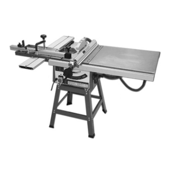
- Page 1 200MM Table Saw Model TS200 Instruction Manual & Parts List Read this operating manual before installation and use to reduce the risk of accidents with the machine...
-
Page 2: Table Of Contents
This manual has been prepared for the owner and operators of Model TS200 200mm table saw. Its purpose, aside from machine operation, is to promote safety through the use of accepted correct operating and maintenance procedures. Completely read the safety and maintenance instructions before operating or servicing the machine. - Page 3 in line with the saw blade or work piece and do not allow anyone else to do so. Never climb on or near the saw. Do not overreach. Use a support table or have a helper or “tailman” take stock away from the back side of the blade.
-
Page 4: Safety Decals
Use proper extension cord: Make sure your extension cord is in good condition. When using an extension cord, be sure to use one heavy enough to carry the current your product will draw. An undersized cord will cause a drop in line voltage resulting in loss of power and overheating. The table below shows the correct size to use depending on cord length and nameplate ampere rating. -
Page 5: Grounding Instructions
……Location Certain types of woods. Press boards, etc. produce hazardous dust emissions when being processed. For this reason, processing procedures must be performed with an exhaust unit(air speed at the connection points: 20m/s) Be sure to switch on the machine and the exhaust unit simultaneously. The main cable plug must be connected as appropriate for the electrical installation and must have an earth lead(or a directly earth conductor for 380 v). -
Page 6: Features
equipment-grounding conductor. If repair or replacement of the electric cord or plug is necessary, do not connect the equipment-grounding conductor to a live terminal. Check with a qualified electrician or service personnel if the grounding instructions are not completely understood, or if in doubt as to whether the tool is properly grounded. Use only three wire extension cords that have three-prong grounding plugs and three-pole receptacles that accept the tool’s plug. -
Page 7: Installation & Assembly
FIG 2 FIG 3 Installation & Assembly Remove the table insert . Block the spindle with current sawing tool; remove the flange (FIG 3)(FIG 4) (thoroughly clean when reassembling) Note the direction of the teeth when replacing the saw blade. Replace the various connection elements (FIG 5) FIG 4 FIG 5... -
Page 8: Adjusting The Longitudinal Limit Stop
longitudinal limit stop to zero on the limit stop guide rail scale and then set the limit stop with the guide rail precisely with respect to the saw blade. Secure the adjustment with the left hexagonal socket screw (FIG 8). (This procedure should be repeated each time the saw blade is replaced.) FIG 8 FIG 9... -
Page 9: Working With The Circular Table Saw
FIG 15 FIG16 Note: The maximum height adjustment must be reduced by 10 mm at pivot angles of 30ºor more. Working with the circular table saw Only use shape, uniformly and sufficiently crossed circular saw blades. Adjust the splitting wedge and fasten it securely. -
Page 10: Cross--Cutting Narrower Work Pieces
FIG19 FIG20 Cross--Cutting narrower work pieces Adjust the guard rail so that the work piece parts are not able to contact the upwards rotating part of the saw blade. Feed work pieces only with a cross limit stop or a cross feeder. (FIG 20) (Caution: No not remove pieces of debris from the sawing tool area with your hands.) Angular limit stop The angular limit stop can be inserted into the machine table T-grooves on the right or left hand side of the... -
Page 11: Malfunctions
Malfunctions Machine vibrates: --Clamping levers for height and diagonal adjustment are not tightly screwed. ---Sawing tool is not tightly screw. Cuts are not clean/wood is burned: ---Sawing tool is dull ---Sawing tool is incorrectly mounted. Rapid sawing tool wear: ---Sawing tool is incorrectly sharpened. ---Contaminated wood(cement, sand , nails). -
Page 12: Parts Lists & Exploded Views Table Saw
PARTS DIAGRAM A... - Page 13 CODE DESCRIPTION CODE DESCRIPTION T0814 Foot Switch assembly Metric bushing M16 GB818-85 Screw M5X16 GB97.1-85 Washerφ5 GB6170-86 Hex nut M5 GB818-85 Screw M6X16 GB97.1-85 Washerφ6 K41925 Saw faceplate GB96-85 Large washer 6 GB6170-86 Hex nut M6 GB5783-86 Hex bolt M6X12 GB/T923 Hex nut M6 GB/T819.1...
- Page 14 K41911 Extending table K41909 Vertical fence K41905 Fence assembly K4192706 Linking plate K4192706 Supporting plate PARTS DIAGRAM B CODE DESCRIPTION CODE DESCRIPTION K0105 C-shaped ring K0104 sliding axle K0103 Eccentric bush GB6172-86 Hex thin nut M8 GB77-85 Set screw M8X25 K0118 Eccentric nut K0117...
-
Page 15: Optional Accessories
PARTS DIAGRAM C CODE DESCRIPTION CODE DESCRIPTION K0707 Dust collector GB5783-86 Hex bolt M8X16 GB96-85 Large washer φ8 K0708 Platen saw blade GB5783-86 Hex bolt M6X16 GB5287-85 Very large washer φ6 K0710 Motor pulley 5PJ422 Cuneal belt K0709 Driven pulley GB894.1-86 “C”ring φ15 GB/T276-94... - Page 16 PARTS DIAGRAM D CODE DESCRIPTION CODE DESCRIPTION K0501 Locking handle GB5783-86 Hex bolt M6X25 GB97.1-85 Washer φ6 K0504 Fixing plate K0503 Locking bracket K0506 Long fence GB70-85 Socket cap screw M6X30 K0507 Rubber tray GB6170-86 Hex nut M6 GB/T96.2-2002 Large erφ6 PARTS DIAGRAM E CODE DESCRIPTION...
- Page 17 WIRING DIAGRAM...