
Related Manuals for Asus P4G8X


Summary of Contents for Asus P4G8X
-
Page 1: P4G8X Deluxe
P4G8X series P4G8X Deluxe P4G8X User Guide NOTE The IEEE 1394, Gigabit LAN, SATA/RAID, and POST Reporter features are present in P4G8X Deluxe models only. - Page 2 Product warranty or service will not be extended if: (1) the product is repaired, modified or altered, unless such repair, modification of alteration is authorized in writing by ASUS; or (2) the serial number of the product is defaced or missing.
-
Page 3: Table Of Contents
How this guide is organized ..........viii Conventions used in this guide ..........ix Where to find more information ..........ix ASUS contact information ............... x P4G8X series specifications summary ........... xi Chapter 1: Product introduction 1.1 Welcome! ................1-1 1.2 Package contents ............... 1-1 1.3 Special features .............. - Page 4 3.3 Powering off the computer ..........3-4 Chapter 4: BIOS setup 4.1 Managing and updating your BIOS ........4-1 4.1.1 Using ASUS EZ Flash to update the BIOS .... 4-1 4.1.2 Using AFLASH to update the BIOS ....... 4-3 4.1.3 CrashFree BIOS feature ........
- Page 5 5.2.1 Running the support CD ........5-1 5.2.2 Drivers menu ............5-2 5.2.3 Utilities menu ............5-5 5.2.4 ASUS Contact Information ........5-6 5.2.5 Other information ........... 5-7 5.3 Software information ............5-9 5.3.1 ASUS Update ............5-9 5.3.2 ASUS MyLogo2™ ..........5-10 5.3.3...
-
Page 6: Federal Communications Commission Statement
Notices Federal Communications Commission Statement This device complies with FCC Rules Part 15. Operation is subject to the following two conditions: • This device may not cause harmful interference, and • This device must accept any interference received including interference that may cause undesired operation. -
Page 7: Safety Information
Safety information Electrical safety • To prevent electrical shock hazard, disconnect the power cable from the electrical outlet before relocating the system. • When adding or removing devices to or from the system, ensure that the power cables for the devices are unplugged before the signal cables are connected. -
Page 8: About This Guide
How this guide is organized This manual contains the following parts: • Chapter 1: Product introduction This chapter describes the features of the P4G8X series motherboard. It includes brief descriptions of the special attributes of the motherboard and the new technology it supports. -
Page 9: Conventions Used In This Guide
1. ASUS Websites The ASUS websites worldwide provide updated information on ASUS hardware and software products. The ASUS websites are listed in the ASUS Contact Information on page x. 2. Optional Documentation Your product package may include optional documentation, such as warranty flyers, that may have been added by your dealer. -
Page 10: Asus Contact Information
Technical Support Support Fax: +1-510-608-4555 General Support: +1-502-933-8713 Web Site: www.asus.com Support Email: tsd@asus.com ASUS COMPUTER GmbH (Germany and Austria) Address: Harkortstr. 25, 40880 Ratingen, BRD, Germany General Fax: +49-2102-442066 General Email: sales@asuscom.de (for marketing requests only) Technical Support Support Hotline:... -
Page 11: P4G8X Series Specifications Summary
Supports PC2100/PC1600 unbuffered ECC or non-ECC DDR DIMMs Expansion slots 1 x AGP Pro/8X (1.5V only) 5 x PCI (includes one ASUS BlueMagic PCI slot) 2 x UltraDMA 100/66/33 connectors Serial ATA (optional) * Silicon Image Sil3112A controller 2 x Serial ATA connectors... - Page 12 CD/AUX/Modem audio connectors (optional) Front panel audio connector (optional) BIOS features 4Mb Flash ROM, Award BIOS, TCAV, PnP, DMI2.0, WfM2.0, SM BIOS2.3, CrashFree BIOS, Multi-language BIOS, ASUS EZ Flash, ASUS C.P.R., ASUS MyLogo2 Industry standard PCI 2.2, USB 2.0 Manageability WfM 2.0.
-
Page 13: Chapter 1: Product Introduction
Chapter 1 This chapter describes the features of the P4G8X motherboard. It includes brief explanations of the special attributes of the motherboard and the new technology it supports. Product introduction... - Page 14 Chapter summary Welcome! ............1-1 Package contents .......... 1-1 Special features ..........1-2 Motherboard overview ........1-6 ASUS P4G8X series motherboard...
-
Page 15: Welcome
Welcome! Thank you for buying the ASUS P4G8X series motherboard! ® The ASUS P4G8X series motherboard delivers a host of new features and latest technologies making it another standout in the long line of ASUS quality motherboards! ® ® The motherboard incorporates the Intel... -
Page 16: Special Features
Special features The IEEE 1394, Gigabit LAN, SATA/RAID, and POST Reporter features are present in P4G8X Deluxe models only. 1.3.1 Product highlights Latest processor technology The motherboard supports the latest Intel ® Pentium ® 4 Processor via a 478-pin surface mount ZIF socket. The Pentium 4 processor with 512KB L2 cache on 0.13 micron process includes a 533/400 MHz system bus and... - Page 17 ASUS EZ Plug™ This patented ASUS technology lets you use your existing power supply rather than buying a new ATX 12V power supply. The ASUS EZ Plug™ is a 4-pin auxiliary +12V connector mounted on the motherboard that connects a regular 4-pin device power connector from the power supply.
-
Page 18: Asus Post Reporter
Visit the ASUS website for information on the supported languages. ASUS EZ Flash BIOS With the ASUS EZ Flash, you can easily update the system BIOS even before loading the operating system. No need to use a DOS-based utility or boot from a floppy disk. -
Page 19: Value-Added Solutions
Temperature, fan, and voltage monitoring The CPU temperature is monitored by the ASUS ASIC to prevent overheating and damage. The system fan rotations per minute (RPM) is monitored for timely failure detection. The system voltage levels are monitored to ensure stable supply of current for critical components. -
Page 20: Motherboard Overview
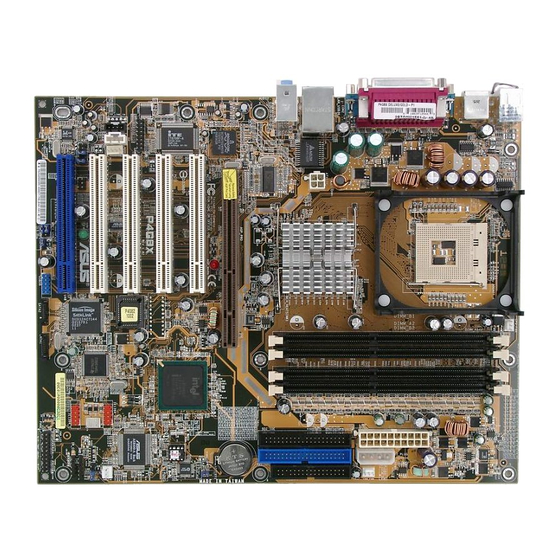
1.4.1 Major components The following are the major components of the P4G8X motherboard as pointed out in the picture on page 1-7. See page 1-8 for the specifications of each component. Refer to Chapter 2 for detailed information on the components. - Page 21 ASUS P4G8X series motherboard user guide...
-
Page 22: Core Specifications
2.1GB/s bandwidth. Speech controller. This Winbond speech controller supports the ASUS POST Reporter™ for configurable vocal POST alerts. ASUS ASIC. This chip performs multiple system functions that include hardware and system voltage monitoring, IRQ routing, among others. Chapter 1: Product introduction... - Page 23 PCI slots. These five 32-bit PCI 2.2 expansion slots support bus master PCI cards like SCSI or LAN cards with 133MB/s maximum throughput. The ASUS proprietary BlueMagic PCI slot (blue slot) supports future ASUS function cards compliant to PCI specification.
- Page 24 ® LAN controller. The BROADCOM BCM5702 Gigabit Ethernet is a single-chip solution for LAN on Motherboard (LOM) and Network Interface Card (NIC) applications. The BCM5702 provides a 32-bit interface and supports 1000/100/10 Mbps data transfer rates. Fast Ethernet models mount the BROADCOM ®...
-
Page 25: Chapter 2: Hardware Information
Chapter 2 This chapter describes the hardware setup procedures that you have to perform when installing system components. It includes details on the switches, jumpers, and connectors on the motherboard. Hardware information... - Page 26 Chapter summary Motherboard installation ....... 2-1 Motherboard layouts ........2-2 Before you proceed ........2-4 Central Processing Unit (CPU) ..... 2-5 System memory ..........2-11 Expansion slots ........... 2-14 Jumpers ............2-17 Connectors ........... 2-19 ASUS P4G8X series motherboard...
-
Page 27: Motherboard Installation
Place nine (9) screws into the holes indicated by circles to secure the motherboard to the chassis. Do not overtighten the screws! Doing so may damage the motherboard. Place this side towards the rear of the chassis ASUS P4G8X series motherboard user guide... -
Page 28: Motherboard Layouts
Motherboard layouts 2.2.1 P4G8X Deluxe 24.5cm (9.6in) PS/2KBMS CPU_FAN T: Mouse B: Keyboard Socket 478 USB2.0 T: USB2 B: USB1 COM1 COM2 Intel E7205 USB2.0 Top: Memory T: USB4 RJ-45 B: USB3 Controller ATX12V Top:Line In Center:Line Out Below:Mic In... -
Page 29: P4G8X
PCI4 CHASSIS SPDIF ® FP_AUDIO SB_PWR IR_CON Audio PCI5/BlueMagic PCI Slot Codec PANEL USB56 USBPW56 WPCI_USB IDE_LED The audio and LAN features are optional. These components are grayed out in the above motherboard layout. ASUS P4G8X series motherboard user guide... -
Page 30: Before You Proceed
1.5V AGP slot, this LED lights up thus preventing the system to power up. This LED remains off if you plug in a 1.5V AGP card. AGP_WARN Incorrect Correct AGP Card AGP Card SB_PWR P4G8X ® Standby Powered P4G8X Onboard LED Power Chapter 2: Hardware information... -
Page 31: Central Processing Unit (Cpu)
3. It is recommended that you install WinXP Service Pack 1. 4. Make sure to enable the Hyper-Threading Technology item in BIOS before installing a supported operating system. 5. For more information on Hyper-Threading Technology, visit www.intel.com/info/hyperthreading. ASUS P4G8X series motherboard user guide... -
Page 32: Installing The Cpu
To use the Hyper-Threading Technology on this motherboard: 1. Buy an Intel Pentium 4 CPU that supports Hyper-Threading Technology. Install the CPU. 2. Power up the system and enter BIOS Setup (see Chapter 4). Under the Advanced Menu, make sure that the item Hyper-Threading Technology is set to Enabled. - Page 33 CPU! 5. When the CPU is in place, push down the socket lever to secure the CPU. The lever clicks on the side tab to indicate that it is locked. ASUS P4G8X series motherboard user guide...
-
Page 34: Installing The Heatsink And Fan
2.4.3 Installing the heatsink and fan ® ® The Intel Pentium 4 Processor requires a specially designed heatsink and fan assembly to ensure optimum thermal condition and performance. When you buy a boxed Intel Pentium 4 Processor, the package includes the heatsink, fan, and retention mechanism. In case you buy a CPU separately, make sure that you use only Intel certified heatsink and fan. - Page 35 Retention Hole Retention Lock Retention Hook Snapped to the Retention Hole Keep the retention locks lifted upward while fitting the retention mechanism to the module base. ASUS P4G8X series motherboard user guide...
-
Page 36: Connecting The Cpu Fan Cable
3. Push down the locks on the retention mechanism to secure the heatsink and fan to the module base. When secure, the retention locks should point to opposite directions. 2.4.4 Connecting the CPU fan cable When the fan, heatsink, and the retention mechanism are in place, connect the CPU fan cable to the connector on the motherboard labeled CPU_FAN. -
Page 37: System Memory
DDR DIMM is single notched while an SDR DIMM is double notched. Therefore, a DDR DIMM is not backward compatible with SDR, and should be installed only in a socket specially designed for DDR DIMMs. ASUS P4G8X series motherboard user guide 2-11... -
Page 38: Memory Configurations
2.5.2 Memory configurations You may install 64MB, 128MB, 256MB, 512MB, and 1GB DDR DIMMs into the DIMM sockets using the memory configurations in this section. Important notes on memory configurations 1. Installing DDR DIMMs other than the recommended configurations may cause memory sizing error or system boot failure. See Table 1 for the recommended configurations. -
Page 39: Installing A Dimm
DIMM. Support the DIMM lightly with your fingers when pressing the retaining clips. The DIMM might get damaged when it flips out with extra force. 2. Remove the DIMM from the socket. ASUS P4G8X series motherboard user guide 2-13... -
Page 40: Expansion Slots
Expansion slots In the future, you may need to install expansion cards. The motherboard has five PCI slots and one Accelerated Graphics Port (AGP) PRO slot. The following sub-sections describe the slots and the expansion cards that they support. Make sure to unplug the power cord before adding or removing expansion cards. -
Page 41: Standard Interrupt Assignments
When using PCI cards on shared slots, ensure that the drivers support “Share IRQ” or that the cards do not need IRQ assignments. Otherwise, conflicts will arise between the two PCI groups, making the system unstable and the card inoperable. ASUS P4G8X series motherboard user guide 2-15... -
Page 42: Pci Slots
2.6.3 PCI slots There are five 32-bit PCI slots on this motherboard, including an ASUS proprietary BlueMagic PCI slot. The slots support PCI cards such as a LAN card, SCSI card, USB card, and other cards that comply with PCI specifications. -
Page 43: Jumpers
P4G8X USB Device Wake Up 2. Wireless PCI and USB settings (3-pin WPCI_USB) These jumpers are reserved. DO NOT change the default settings. WPCI_USB Wireless Original P4G8X PCI_USB reserved pin ® (Default) P4G8X WPCI_USB Setting ASUS P4G8X series motherboard user guide 2-17... -
Page 44: Clear Rtc Ram
Normal Clear CMOS (Default) P4G8X Clear RTC RAM You do not need to clear the RTC when the system hangs due to overclocking. For system failure due to overclocking, use the C.P.R. (CPU Parameter Recall) feature. Shut down and reboot the system so BIOS can automatically reset parameter settings to default values. -
Page 45: Connectors
(Pin 5 is removed to prevent incorrect insertion when using ribbon cables with pin 5 plug). FLOPPY NOTE: Orient the red markings on the floppy ribbon cable to PIN 1. P4G8X PIN 1 ® P4G8X Floppy Disk Drive Connector ASUS P4G8X series motherboard user guide 2-19... - Page 46 NOTE: Orient the red markings (usually zigzag) on the IDE ribbon cable to PIN 1. P4G8X ® P4G8X IDE Connectors PIN 1 For UltraDMA/100/66 IDE devices, use an 80-conductor IDE cable. The UltraDMA/66 cable included in the motherboard package also supports UltraDMA/100.
- Page 47 By default, the pins labeled “Chassis Signal” and “Ground” are shorted with a jumper cap. If you wish to use the chassis intrusion detection feature, remove the jumper cap from the pins. CHASSIS P4G8X ® (Default) P4G8X Chassis Alarm Lead ASUS P4G8X series motherboard user guide 2-21...
- Page 48 These are not jumpers! DO NOT place jumper caps on the fan connectors! CPU_FAN CHA_FAN +12V Rotation PWR_FAN P4G8X ® P4G8X 12-Volt Fan Connectors 2-22 Chapter 2: Hardware information...
- Page 49 CPU. If you are using a standard ATX power supply that does not have the ATX +12V plug, connect one 4-pin device power plug to the ASUS EZ Plug™ connector labeled EZ_PLUG. Make sure that your ATX 12V power supply can provide 8A on the +12V lead and at least 1A on the +5-volt standby lead (+5VSB).
- Page 50 S/PDIF module. P4G8X SPDIF ® P4G8X Digital Audio Connector 10. GAME/MIDI connector (16-1 pin GAME) This connector supports a GAME/MIDI module. If your package came with the USB 2.0/GAME module, connect the GAME/MIDI cable to this connector.
- Page 51 You must install the driver before you can use the USB 2.0 capability. USB56 P4G8X (Blue) ® P4G8X USB 2.0 Header NEVER connect a 1394 cable to the USB56 connector. Doing so will damage the motherboard! ASUS P4G8X series motherboard user guide 2-25...
- Page 52 Left Audio Channel P4G8X Ground Ground ® Right Audio Channel P4G8X Internal Audio Connectors 13. Power supply thermal connector (2-pin TRPWR) If your power supply has a thermal monitoring feature, connect its thermal sensor cable to this connector. TRPWR Power Supply...
- Page 53 You may also connect a 1394-compliant internal hard disk to these connectors. IE1394_2 P4G8X IE1394_1 ® P4G8X IEEE-1394 Connectors NEVER connect a USB cable to any of the IEEE 1394 connectors. Doing so will damage the motherboard! ASUS P4G8X series motherboard user guide 2-27...
- Page 54 LINE OUT_L/BLINE_OUT_L are shorted with jumper caps. Remove the caps only when you are connecting the front panel audio cable. FP_AUDIO P4G8X ® P4G8X Front Panel Audio Connector 17. System panel connector (20-pin PANEL) This connector accommodates several system front panel functions. Keyboard Lock Speaker...
- Page 55 Pressing the power switch while in the ON mode for more than 4 seconds turns the system OFF. • Reset Switch Lead (2-pin RESET) This 2-pin connector connects to the case-mounted reset switch for rebooting the system without turning off the system power. ASUS P4G8X series motherboard user guide 2-29...
- Page 56 2-30 Chapter 2: Hardware information...
-
Page 57: Chapter 3: Powering Up
Chapter 3 This chapter describes the power up sequence and gives information on the BIOS beep codes. Powering up... - Page 58 Chapter summary Starting up for the first time ......3-1 Vocal POST Messages ........3-2 Powering off the computer ......3-4 ASUS P4G8X series motherboard...
-
Page 59: Starting Up For The First Time
System running at a lower frequency You will not hear the BIOS beeps when the ASUS POST Reporter™ is enabled. You will hear the vocal POST messages instead. 7. At power on, hold down <Delete> to enter BIOS Setup. Follow the instructions in Chapter 4. -
Page 60: Vocal Post Messages
Vocal POST Messages This motherboard includes the Winbond speech controller to support a special feature called the ASUS POST Reporter™. This feature gives you vocal POST messages and alerts to inform you of system events and boot status. In case of a boot failure, you will hear the specific cause of the problem. - Page 61 System completed Power-On Self Test • No action required Computer now booting from operating • No action required system You may disable the ASUS POST Reporter™ in the BIOS setup. See section “4.4.2 I/O Device Configuration”. ASUS P4G8X series motherboard user guide...
-
Page 62: Powering Off The Computer
Powering off the computer You must first exit the operating system and shut down the system before switching off the power. For ATX power supplies, you can press the ATX power switch after exiting or shutting down the operating system. If you use Windows ME/2000/XP, click the Start button, click Shut Down, then click the OK button to shut down the computer. -
Page 63: Chapter 4: Bios Setup
Chapter 4 This chapter tells how to change system settings through the BIOS Setup menus. Detailed descriptions of the BIOS parameters are also provided. BIOS setup... - Page 64 Chapter summary Managing and updating your BIOS ....4-1 BIOS Setup program ........4-8 Main Menu ............. 4-11 Advanced Menu ........... 4-18 Power Menu ..........4-28 Boot Menu ............ 4-34 Exit Menu ............4-36 ASUS P4G8X series motherboard...
-
Page 65: Managing And Updating Your Bios
BIOS later. 4.1.1 Using ASUS EZ Flash to update the BIOS The ASUS EZ Flash feature allows you to easily update the BIOS without having to go through the long process of booting from a diskette and using a DOS-based utility. The EZ Flash is built-in the BIOS firmware so it is accessible by simply pressing <Alt>... - Page 66 5. At the prompt, , type in the “Please Enter File Name for NEW BIOS: _” BIOS file name that you downloaded from the ASUS website, then press <Enter>. EZ Flash will automatically access drive A to look for the file name that you typed.
-
Page 67: Using Aflash To Update The Bios
If the word “unknown” appears after Flash Memory:, the memory chip is either not programmable or is not supported by the ACPI BIOS and therefore, cannot be programmed by the Flash Memory Writer utility. ASUS P4G8X series motherboard user guide... - Page 68 5. Select 1. Save Current BIOS to File from the Main menu and press <Enter>. The Save Current BIOS To File screen appears. 6. Type a filename and the path, for example, A:\XXX-XX.XXX, then press <Enter>. Chapter 4: BIOS Setup...
- Page 69 BIOS revision will solve your problems. Careless updating may result to more problems with the motherboard! 1. Download an updated ASUS BIOS file from the Internet (WWW or FTP) (see ASUS CONTACT INFORMATION on page x for details) and save to the boot floppy disk you created earlier.
- Page 70 If the Flash Memory Writer utility is not able to successfully update a complete BIOS file, the system may not boot. If this happens, call the ASUS service center for support. Chapter 4: BIOS Setup...
-
Page 71: Crashfree Bios Feature
1. Turn on the computer, and when prompted, place the bootable floppy disk into the floppy drive, so that the computer boots from the floppy disk. 2. Follow the BIOS update procedure in section “4.1.2 Using AFLASH to update the BIOS.” ASUS P4G8X series motherboard user guide... -
Page 72: Bios Setup Program
BIOS Setup program This motherboard supports a programmable Flash ROM that you can update using the provided utility described in section “ 4.1 Managing and updating your BIOS.” Use the BIOS Setup program when you are installing a motherboard, reconfiguring your system, or prompted to “Run Setup”. This section explains how to configure your system using this utility. -
Page 73: Bios Menu Bar
<Home> or <PgUp> Moves the cursor to the first field <End> or <PgDn> Moves the cursor to the last field <F5> Resets the current screen to its Setup Defaults <F10> Saves changes and exits Setup ASUS P4G8X series motherboard user guide... -
Page 74: General Help
General help In addition to the Item Specific Help window, the BIOS setup program also provides a General Help screen. You may launch this screen from any menu by simply pressing <F1> or the <Alt> + <H> combination. The General Help screen lists the legend keys and their corresponding functions. -
Page 75: Main Menu
Floppy 3 Mode Support [Disabled] This is required to support older Japanese floppy drives. The Floppy 3 Mode feature allows reading and writing of 1.2MB (as opposed to 1.44MB) on a 3.5-inch diskette. Configuration options: [Disabled] [Enabled] ASUS P4G8X series motherboard user guide 4-11... - Page 76 Language [English US] This field allows you to choose the BIOS language version from the available options. Supervisor Password [Disabled] / User Password [Disabled] These fields allow you to set passwords. To set a password, highlight the appropriate field and press <Enter>. Type in a password then press <Enter>.
-
Page 77: Primary And Secondary Master/Slave
Before attempting to configure a hard disk drive, make sure you have the correct configuration information supplied by the drive manufacturer. Incorrect settings may cause the system to fail to recognize the installed hard disk. ASUS P4G8X series motherboard user guide 4-13... - Page 78 [User Type HDD] Manually enter the number of cylinders, heads and sectors per track for the drive. Refer to the drive documentation or on the drive label for this information. After entering the IDE hard disk drive information into BIOS, use a disk utility, such as FDISK, to partition and format new IDE hard disk drives.
- Page 79 This field shows the drive’s maximum CHS capacity as calculated by the BIOS based on the drive information you entered. Maximum LBA Capacity This field shows the drive’s maximum LBA capacity as calculated by the BIOS based on the drive information you entered. ASUS P4G8X series motherboard user guide 4-15...
- Page 80 Multi-Sector Transfers [Maximum] This option automatically sets the number of sectors per block to the highest number that the drive supports. Note that when this field is automatically configured, the set value may not always be the fastest value for the drive. You may also manually configure this field. Refer to the documentation that came with the hard drive to determine the optimum value and set it manually.
-
Page 81: Keyboard Features
[6/Sec] [8/Sec] [10/Sec] [12/Sec] [15/Sec] [20/Sec] [24/Sec] [30/Sec] Keyboard Auto-Repeat Delay [1/4 Sec] This field sets the time interval for displaying the first and second characters. Configuration options: [1/4 Sec] [1/2 Sec] [3/4 Sec] [1 Sec] ASUS P4G8X series motherboard user guide 4-17... -
Page 82: Advanced Menu
Advanced Menu CPU Speed [Manual] When the motherboard is set to JumperFree™ mode, this field allows you to select the internal frequency of the CPU. Select [Manual] if you want to make changes to the two subsequent fields. Note that selecting a frequency higher than the CPU manufacturer recommends may cause the system to hang or crash. - Page 83 Refer to the CPU documentation before setting this field. A very high core voltage may severely damage the CPU! AGP Voltage [1.5V] This item controls the AGP operating voltage. Configuration options: [1.5V] [1.6V] [1.7V] ASUS P4G8X series motherboard user guide 4-19...
- Page 84 DDR Voltage [2.5V] This item controls the DDR SDRAM operating voltage. Configuration options: [2.5V] [2.6V] [2.7V] CPU Level 1 Cache, CPU Level 2 Cache [Enabled] These fields allow you to choose from the default [Enabled] or choose [Disabled] to turn on or off the CPU Level 1 and Level 2 built-in cache. Configuration options: [Disabled] [Enabled] BIOS Update [Enabled] This field functions as an update loader integrated into the BIOS to supply...
-
Page 85: Chip Configuration
Configuration options: [3T] [2T]. SDRAM RAS Precharge Delay (value depends on SDRAM SPD) This item controls the idle clocks after issuing a precharge command to the DDR SDRAM. Configuration options: [3T] [2T] ASUS P4G8X series motherboard user guide 4-21... - Page 86 SDRAM Active Precharge Delay (value depends on SDRAM SPD) This item controls the number of DDR SDRAM clocks used for DDR SDRAM parameters. Configuration options: [7T] [6T] [5T] SDRAM Idle Timer [16T] Configuration options: [Infinite] [16T] Graphics Aperture Size [64MB] This feature allows you to select the size of mapped memory for AGP graphic data.
-
Page 87: I/O Device Configuration
This field allows you to set the address of the onboard parallel port connector. If you disable this field, the Parallel Port Mode and ECP DMA Select configurations are not available. Configuration options: [Disabled] [378H/IRQ7] [278H/IRQ5] ASUS P4G8X series motherboard user guide 4-23... - Page 88 Configuration options: [3] [4] [5] [7] [9] [10] [11] [12] [14] [15] Speech POST Reporter [Enabled] This field enables or disables the ASUS POST Reporter™ feature. See section “1.3 Special Features” and “3.2 Vocal POST messages” for more information. Configuration options: [Disabled] [Enabled] Make sure that the Onboard AC97 Audio Controller item is enabled.
-
Page 89: Pci Configuration
Leave this field to the default setting [32] for best performance and stability. USB 1.1 Controllers [3 Controllers] This field allows you to select the number of USB 1.1 controllers that you wish to activate. Configuration options: [Disabled] [3 Controllers] ASUS P4G8X series motherboard user guide 4-25... - Page 90 USB 2.0 Controller [Enabled] This field allows you to enable or disable the onboard USB 2.0 controller. Set to [Enabled] if you wish to install USB 2.0 devices. Configuration options: [Disabled] [Enabled] Primary VGA BIOS [PCI VGA Card] This field allows you to select the primary graphics card. Configuration options: [PCI VGA Card] [AGP VGA Card] Onboard LAN [Enabled] This field allows you to enable or disable the onboard LAN controller.
-
Page 91: Pci Irq Resource Exclusion
IRQ is NOT required by a legacy ISA card. Set the IRQ field to [Yes] if you install a legacy ISA card that requires a unique IRQ and you are NOT using ICU. Configuration options: [No/ICU] [Yes] ASUS P4G8X series motherboard user guide 4-27... -
Page 92: Power Menu
Power Menu The Power menu allows you to reduce power consumption. This feature turns off the video display and shuts down the hard disk after a period of inactivity. Power Management [User Defined] This field allows you to activate or deactivate the automatic power saving features. - Page 93 This item allows you to enable or disable the processor Hyper-Threading Technology. Configuration options: [Disabled] [Enabled] The item Hyper-Threading Technology appears only if you installed an Intel Pentium 4 CPU that supports this feature. ASUS P4G8X series motherboard user guide 4-29...
-
Page 94: Power Up Control
Suspend Mode [Disabled] Sets the time period before the system goes into suspend mode. Configuration options: [Disabled] [1~2 Min] [2~3 Min] [4~5 min] [8~9 Min] [20 Min] [30 Min][40 Min] [1 Hour] PWR Button < 4 Secs [Soft Off] When set to [Soft off], the ATX switch can be used as a normal system power-off button when pressed for less than 4 seconds. - Page 95 [Everyday] or at a certain time and day by selecting [By Date]. Configuration options: [Disabled] [Everyday] [By Date] ASUS P4G8X series motherboard user guide 4-31...
-
Page 96: Hardware Monitor
4.5.2 Hardware Monitor MB Temperature [xxxC/xxxF] CPU Temperature [xxxC/xxxF] POWER Temperature [Ignore] The onboard hardware monitor automatically detects and displays the motherboard and CPU temperatures. If your power supply comes with a two-pin thermal sensor cable, connect this cable to the TRPWR connector on the motherboard to allow BIOS to auto-detect the power supply temperature (see page 2-26 for the location of the TRPWR connector). - Page 97 DEL to enter SETUP”. Q-Fan Control [Disabled] This item allows you to enable or disable the ASUS Q-Fan feature that smartly adjusts the fan speeds for more efficient system operation. When this field is set to [Enabled], the...
-
Page 98: Boot Menu
Boot Menu Boot Sequence The Boot menu allows you to select among the four possible types of boot devices listed using the up and down arrow keys. By using the <+> or <Space> key, you can promote devices and by using the <-> key, you can demote devices. - Page 99 The Advanced Programmable Interrupt Controller (APIC) setting allows you to distribute interrupt routings other than the 16 IRQs. The Programmable Interrupt Controller (PIC) setting allows you to use the 16 IRQs only. Configuration options: [PIC] [APIC] ASUS P4G8X series motherboard user guide 4-35...
-
Page 100: Exit & Save Changes
Exit Menu When you have made all of your selections from the various menus in the Setup program, save your changes and exit Setup. Select Exit from the menu bar to display the following menu. Pressing <Esc> does not immediately exit this menu. Select one of the options from this menu or <F10>... -
Page 101: Discard Changes
This option saves your selections without exiting the Setup program. You can then return to other menus and make further changes. After you select this option, a confirmation window appears. Select [Yes] to save any changes to the non-volatile RAM. ASUS P4G8X series motherboard user guide 4-37... - Page 102 4-38 Chapter 4: BIOS Setup...
-
Page 103: Chapter 5: Software Support
Chapter 5 This chapter describes the contents of the support CD that comes with the motherboard package. Software support... - Page 104 Chapter summary Install an operating system ......5-1 Support CD information ........ 5-1 Software information ........5-9 RAID 0/RAID 1 configurations ....5-23 ASUS P4G8X series motherboard...
-
Page 105: Install An Operating System
The contents of the support CD are subject to change at any time without notice. Visit the ASUS website for updates. 5.2.1 Running the support CD To begin using the support CD, simply insert the CD into your CD-ROM drive. -
Page 106: Drivers Menu
5.2.2 Drivers menu The drivers menu shows the available device drivers if the system detects installed devices. Install the necessary drivers to activate the devices. The SATA and LAN items appear on P4G8X Deluxe models only. Intel Chipset Inf Update program ®... - Page 107 1. Right-click My Computer icon on your desktop, and select Properties to display the System Properties window. 2. On the System Properties window, click on the Hardware tab. Click on the Device Manager button to display the Device Manager window. ASUS P4G8X series motherboard user guide...
- Page 108 3. On the Device Manager window, click the plus sign (+) opposite the Network adapters item to show the ASUSTeK/BroadCom 440x 10/100 Integrated Controller. Double-click the item. 4. On the window that appears, click the item Wake Up Capabilities under Property. The default value is Wake Up Frame.
-
Page 109: Utilities Menu
The Winbond Voice Editor appears on P4G8X Deluxe models only. Winbond Voice Editor This program is for recording and customizing wave files for the ASUS POST Reporter™. Use this program if you wish to change the default vocal POST messages. See section “3.2 Vocal POST messages” for a list of the default messages. -
Page 110: Asus Contact Information
5.2.4 ASUS Contact Information Clicking the ASUS Contact Information tab displays as stated. You may also find this information on page x of this user guide. Chapter 5: Software support... -
Page 111: Other Information
CD. Click an icon to display the specified information. Motherboard Info The window displays the general specifications of the P4G8X motherboard. Browse this CD The window displays the support CD contents in graphical format. - Page 112 Technical Support Form The window displays the ASUS Technical Support Request Form that you have to fill up when requesting technical support. Filelist The window displays the contents of the support CD and a brief description of each in text format.
-
Page 113: Software Information
This section provides details on the software applications that the motherboard supports. 5.3.1 ASUS Update The ASUS Update is a utility that allows you to update the motherboard BIOS and drivers. This utility requires an Internet connection either through a network or an Internet Service Provider (ISP). -
Page 114: Asus Mylogo2
5.3.2 ASUS MyLogo2™ The ASUS MyLogo2™ is automatically installed when you install the ASUS Update utility from the software menu. See section “5.2.3 Software menu”. Before using ASUS MyLogo2 feature, use the AFLASH utility to make a copy of your original BIOS file, or obtain the latest BIOS version from the ASUS website. - Page 115 Your system boots with the new boot logo. Instead of starting from ASUS Update, you may also launch ASUS MyLogo2 directly from the Windows Start menu to change your BIOS boot logo. After you have modified the BIOS file with the new logo, use the ASUS Update utility to upload the new BIOS.
-
Page 116: Asus Pc Probe
, and then click Programs ASUS Utility Probe Vx.xx The PC Probe icon appears on the taskbar system tray indicating that ASUS PC Probe is running. Clicking the icon allows you to see the status of your PC. 5-12 Chapter 5: Software support... - Page 117 Fan Monitor Shows the PC fan rotation. Fan Warning threshold adjustment (Move the slider up to increase the threshold level or down to decrease the threshold level) Voltage Monitor Shows the PC voltages. ASUS P4G8X series motherboard user guide 5-13...
- Page 118 Settings Lets you set threshold levels and polling intervals or refresh times of the PC’s temperature, fan rotation, and voltages. CPU Cooling System Setup Lets you select when to enable software CPU cooling. When When CPU Overheated is selected, the CPU cooling system is enabled whenever the CPU temperature reaches the threshold value.
- Page 119 PC, such as CPU type, CPU speed, and internal/external frequencies, and memory size. Utility Lets you run programs outside of the ASUS Probe modules. To run a program, click Execute Program NOTE: This feature is currently unavailable. ASUS P4G8X series motherboard user guide...
- Page 120 ASUS PC Probe Task Bar Icon Right clicking the PC Probe icon brings up a menu to open or exit ASUS PC Probe and pause or resume all system monitoring. When the ASUS PC Probe senses a problem with your PC,...
-
Page 121: Winbond Voice Editor
Playing the default wave files To play the default wave files, simply click on a POST event on the left side of the screen, then click the Play button. The default language setting is English. ASUS P4G8X series motherboard user guide 5-17... - Page 122 Changing the default language 1. Click on the Load button. a window showing the available languages appears. 2. Select your desired language then click Open. The event messages for the language you selected appear on the Voice Editor screen. For some languages, not all events have a corresponding message due to file size constraints.
- Page 123 5. From the Voice Editor screen, click on the Add button to display the Add Wave File window. 6. Copy the wave files that you recorded to the database. Close the window when done. ASUS P4G8X series motherboard user guide 5-19...
- Page 124 7. Click a POST event on the Voice Editor screen, then on the Edit button. The Event Sound Editor window appears. 8. Locate and select your wave file for the event then click on the arrow opposite Voice1. The file you selected appears on the space next to it.
-
Page 125: Multi-Channel Audio Feature
4. Click on the Equalizer tab to display the individual control frequency bands, and adjust the sound output. You may alsodisplay the Equalizer panel by clicking on the Equalizer command button on the Sound Effect tab. ASUS P4G8X series motherboard user guide 5-21... -
Page 126: Rear Panel Audio Ports Function Variation
5. Click on the Speaker Configuration tab to customize your speaker system. 6. Click on the Speaker Test tab to test the multi-channel audio configuration. 7. Click on the SPDIF-In tab to configure S/PDIF settings. By default, the SPDIF Out function is enabled. -
Page 127: Raid 0/Raid 1 Configurations
For example, one hard disk has an 80GB storage capacity and the other hard disk has 60GB storage capacity, the maximum storage capacity for the RAID 1 set is 60GB. ASUS P4G8X series motherboard user guide 5-23... -
Page 128: Creating And Deleting Raid Sets
Follow these steps to install the hard disks for RAID configuration. 1. Install the Serial ATA hard disks into the drive bays. 2. Connect one Serial ATA HDD to each Serial ATA connector, using separate serial ATA cables. 4. Connect the power cable to the power connector on each drive. 5. -
Page 129: Creating Raid Sets
To resolve this, select the option Resolve Conflict so that the correct metadata (including the correct drive connection information) may be written to the replacement disk. ASUS P4G8X series motherboard user guide 5-25... - Page 130 5-26 Chapter 5: Software support...
-
Page 131: Index
Index This part contains an alphabetical list of the topics found in this document. - Page 132 ASUS P4G8X series motherboard...
- Page 133 DDR SDRAM technology 2-11 Boot Device Digital audio interface 1-3 selection 4-35 DIMM Boot Up NumLock Status 4-16 installing 2-13 Boot Virus Detection 4-36 removing 2-14 DIMM sockets 1-8 Double Data Rate (DDR) memory 1-2 ASUS P4G8X series motherboard user guide...
- Page 134 Expansion card Keyboard installation 2-14 Auto-Repeat Delay 4-16 configuration 2-14 Auto-Repeat Rate 4-16 Expansion slots 1-9, 2-14 AGP 1-10, 2-16 PCI 1-10, 2-16 LEDs AGP warning 1-10, 2-3 standby power 1-10, 2-3 Flash ROM 1-9 Legacy Diskette 4-10 Floppy 3 Mode 4-10 Floppy disk access control 4-24 Motherboard major components 1-6...
- Page 135 Drivers menu 5-2 motherboard information 5-7 multi-channel audio 5-21 Technical Support Form 5-8 Suspend Mode 4-29 System Controller North Bridge 1-8 South Bridge 1-9 System Date 4-10 System memory configurations 2-11 System Time 4-10 ASUS P4G8X series motherboard user guide...
- Page 136 Index...