Table of Contents
Advertisement
Advertisement
Table of Contents

Related Manuals for Asus P4S800


Summary of Contents for Asus P4S800
- Page 1 P4S800 User Guide...
- Page 2 Product warranty or service will not be extended if: (1) the product is repaired, modified or altered, unless such repair, modification of alteration is authorized in writing by ASUS; or (2) the serial number of the product is defaced or missing.
-
Page 3: Table Of Contents
1.12 Connectors ............... 1-18 Chapter 2: BIOS information 2.1 Managing and updating your BIOS ........2-2 2.1.1 Using ASUS EZ Flash to update the BIOS .... 2-2 2.1.2 Using AFLASH to update the BIOS ....... 2-3 2.1.3 CrashFree BIOS 2 feature ........2-6... - Page 4 3.2 Support CD information ............3-2 3.2.1 Running the support CD ........3-2 3.2.2 Drivers menu ............3-3 3.2.3 Utilities menu ............3-3 3.2.4 ASUS Contact Information ........3-4 3.3 Software information ............3-4 3.3.1 ASUS Instant Music ..........3-4...
-
Page 5: Notices
Notices Federal Communications Commission Statement This device complies with Part 15 of the FCC Rules. Operation is subject to the following two conditions: • This device may not cause harmful interference, and • This device must accept any interference received including interference that may cause undesired operation. -
Page 6: Safety Information
Safety information Electrical safety • To prevent electrical shock hazard, disconnect the power cable from the electrical outlet before relocating the system. • When adding or removing devices to or from the system, ensure that the power cables for the devices are unplugged before the signal cables are connected. -
Page 7: About This Guide
1. ASUS Websites The ASUS websites worldwide provide updated information on ASUS hardware and software products. The ASUS websites are listed in the ASUS Contact Information on page viii. 2. Optional Documentation Your product package may include optional documentation, such as warranty flyers, that may have been added by your dealer. -
Page 8: Asus Contact Information
Web site usa.asus.com Technical Support Telephone (General) +1-502-995-0883 (Notebook) +1-510-739-3777 Support fax +1-502-933-8713 Support e-mail tsd@asus.com ASUS COMPUTER GmbH (Germany and Austria) Address Harkort Str. 25, D-40880 Ratingen, Germany Telephone +49-2102-95990 +49-2102-959911 Online contact www.asuscom.de/sales Technical Support Telephone +49-2102-95990 +49-2102-959911 Online support www.asuscom.de/support... -
Page 9: P4S800 Specifications Summary
2 DIMMs; 1 GB PC3200/2700 with 32 DDR chips support to 1 DIMM only.) Expansion slots 1 x AGP 8X (1.5V only) 5 x PCI 1 x ASUS Proprietary WiFi Wireless LAN connection 2 x UltraDMA 133/100/66/33 connectors ADI AD1980 6-channel audio CODEC Audio S/PDIF out interface Integrated 10/100 Mbps LAN controller + VIA VT6103 PHY USB 2.0... - Page 10 CD/AUX audio connectors Front panel audio connector S/PDIF out connector BIOS features 2Mb Flash ROM, ASUS JumperFree,Award BIOS, TCAV, PnP, DMI2.0, WfM2.0, SM BIOS2.3, ASUS EZ Flash, ASUS CrashFree BIOS 2, ASUS C.P.R. Industry standard PCI 2.2, USB 2.0 Manageability WfM 2.0, DMI 2.0, WOL/WOR by PME, Chassis intrusion,...
-
Page 11: Chapter 1: Product Introduction
Chapter 1 This chapter describes the features of the P4S800 motherboard. It includes brief descriptions of the motherboard components, and illustrations of the layout, jumper settings, and connectors. Product introduction... -
Page 12: Welcome
Supporting up to 3GB of system memory with the PC3200/2700/2100/1600 DDR DIMMs, high-resolution graphics via an AGP 8X slot, USB 2.0 and 6-channel audio features, the P4S800 is your affordable vehicle to enter the world of computing! Before you start installing the motherboard and hardware devices on it, check the items in your package with the list below. -
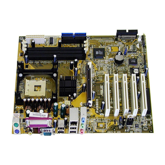
Page 13: Motherboard Components
Motherboard components Before you install the motherboard, learn about its major components and available features to facilitate the installation and future upgrades. Refer to the succeeding pages for the component descriptions. ASUS P4S800 motherboard user guide... - Page 14 ATX 12V connector. This power connector connects the 4-pin 12V plug from the ATX 12V power supply. CPU socket. A 478-pin surface mount, Zero Insertion Force (ZIF) socket for ® ® the Intel Pentium 4 Processor, with 800/533/400 MHz system bus that allows 6.4GB/s, 4.3GB/s and 3.2GB/s data transfer rates, respectively.
- Page 15 Serial port. This 9-pin COM1 port is for pointing devices or other serial devices. S/PDIF jack. This jack connects to external audio output devices. PS/2 keyboard port. This purple connector is for a PS/2 keyboard. ASUS P4S800 motherboard user guide...
-
Page 16: Special Features
Special Features 1.4.1 Product highlights With the SiS 648FX chipset, the ASUS P4S800 supports latest 800MHz front side ® bus and Intel next generation Prescott CPU. In addition to supporting high- bandwidth DDR400, unique MuTIOL technology increases the bus speed between the northbridge and southbridge to 1GB/sec for enhanced system performance. -
Page 17: Asus Instant Music Lite
Windows. (The stickers on keyboard are separately purchased.) The P4S800 Instant Music Lite feature can only be used on PS/2 keyboards. ASUS EZ Flash With ASUS EZ Flash, you can update BIOS before entering operating system. No more DOS-based flash utility and bootable diskette required. -
Page 18: Motherboard Layout
USBPW34 USB12 648FX CPU_FAN Chip ATX12V Bottom: Top: USB3 RJ-45 USB4 Top:Line In Center:Line Out Below:Mic In Accelerated Graphics Port (AGP) P4S800 963L ® Chipset PCI1 PCI2 SPDIF_OUT CR2032 3V FP_AUDIO Lithium Cell CMOS Power PCI3 CLRTC CHASSIS PCI4 Audio... -
Page 19: Before You Proceed
When installing the motherboard, make sure that you place it into the chassis in the correct orientation. The edge with external ports goes to the rear part of the chassis as indicated in the image below. ASUS P4S800 motherboard user guide... -
Page 20: Screw Holes
1.7.2 Screw holes Place nine (9) screws into the holes indicated by circles to secure the motherboard to the chassis. Do not overtighten the screws! Doing so may damage the motherboard. Place this side towards the rear of the chassis Central Processing Unit (CPU) 1.8.1 Overview The motherboard comes with a surface mount 478-pin Zero Insertion Force (ZIF) -
Page 21: Installing The Cpu
6. Install a CPU heatsink and fan following the instructions that came with the heatsink package. 7. Connect the CPU fan cable to the CPU fan connector on the motherboard. ASUS P4S800 motherboard user guide 1-11... -
Page 22: System Memory
1 GB PC3200/2700 with 32 DDR chips support to 1 DIMM only. P4S800 ® P4S800 184-Pin DDR DIMM Sockets • Make sure to unplug the power supply before adding or removing DIMMs or other system components. Failure to do so may cause severe damage to the motherboard and other system components. -
Page 23: Qualified Vendor List
TwinMOS /D M2G9J16AGATT9F081AA4T TwinMOS TMD7608F8FE50D 512MB TwinMOS /S M2S9I08AFAPS9F0811A-T A2S56D30ATP 256MB TwinMOS /D M2G9J16AGATT9F081AA4T TwinMOS TMD7608F8E50D 512MB Winbond /D W9451GCDB-5 Winbond W942508CH-5 512MB LEGEND: /S - Single Sided DIMMs /D - Double Sided DIMMs ASUS P4S800 motherboard user guide 1-13... -
Page 24: Expansion Slots
1.10 Expansion slots The motherboard has five PCI slots, one Accelerated Graphics Port slot and the ASUS proprietary Wireless Fidelity (WiFi) slot. To install and configure an expansion card: 1. Install an expansion card following the instructions that came with the chassis. -
Page 25: Standard Interrupt Assignments
When using PCI cards on shared slots, ensure that the drivers support “Share IRQ” or that the cards do not need IRQ assignments. Otherwise, conflicts will arise between the two PCI groups, making the system unstable and the card inoperable. ASUS P4S800 motherboard user guide 1-15... -
Page 26: Jumpers
(no power to CPU, DRAM in slow refresh, power supply in reduced power mode). The rear panel USB ports (Ports 1 to 4) do not support device wake-up from S4 sleep mode. USBPW12 USBPW34 +5VSB (Default) P4S800 ® USBPW56 +5VSB P4S800 USB Device Wake Up (Default) 1-16 Chapter 1: Product introduction... -
Page 27: Clear Rtc Ram (Clrtc)
You do not need to clear the RTC when the system hangs due to overclocking. For system failure due to overclocking, use the C.P.R. (CPU Parameter Recall) feature. Shut down and reboot the system so BIOS can automatically reset parameter settings to its previous state. ASUS P4S800 motherboard user guide 1-17... -
Page 28: Connectors
PIN 1. P4S800 ® P4S800 Floppy Disk Drive Connector 2. IDE connectors (40-1 pin PRI_IDE, SEC_IDE) This connector supports the provided UltraDMA133/100/66 IDE hard disk ribbon cable. Connect the cable’s blue connector to the primary (recommended) or... - Page 29 By default, the pins labeled “Chassis Signal” and “Ground” are shorted with a jumper cap. If you wish to use the chassis intrusion detection feature, remove the jumper cap from the pins. CHASSIS P4S800 ® (Default) P4S800 Chassis Alarm Lead ASUS P4S800 motherboard user guide 1-19...
- Page 30 ® CHA_FAN Rotation +12V P4S800 12-Volt Fan Connectors 6. GAME/MIDI connector (16-1 pin GAME) This connector supports a GAME/MIDI module. Connect an optional GAME/MIDI cable to this connector. The GAME/MIDI port on the module connects a joystick or a game pad for playing games, and MIDI devices for playing or editing audio files.
- Page 31 P4S800 ® FP_AUDIO P4S800 Front Panel Audio Connector 9. WiFi connector (63-pin WIFI) This slot supports the ASUS proprietary WiFi (Wireless Fidelity) module. P4S800 ® WIFI P4S800 Wi-Fi Slot ASUS P4S800 motherboard user guide...
- Page 32 P4S800 USB 2.0 Header 11. Digital audio connector (4-1 pin SPDIF_OUT) This connector is for a S/PDIF audio module that allows digital instead of analog sound output. If the S/PDIF out port at the rear panel is inadequate use this to connect one end of the audio cable to the S/PDIF_OUT connector on the motherboard, and the other end to the S/PDIF module.
- Page 33 Hard Disk Activity Lead (2-pin IDE_LED) This connector supplies power to the hard disk activity LED. The read or write activities of any device connected to the primary or secondary IDE connector cause this LED to light up. ASUS P4S800 motherboard user guide 1-23...
- Page 34 1-24 Chapter 1: Product introduction...
-
Page 35: Chapter 2: Bios Information
Chapter 2 This chapter tells how to change system settings through the BIOS Setup menus. Detailed descriptions of the BIOS parameters are also provided. BIOS information... -
Page 36: Managing And Updating Your Bios
BIOS later. 2.1.1 Using ASUS EZ Flash to update the BIOS The ASUS EZ Flash feature allows you to easily update the BIOS without having to go through the long process of booting from a diskette and using a DOS-based utility. -
Page 37: Using Aflash To Update The Bios
It is recommended that you reboot using a floppy disk. 3. Reboot the computer from the floppy disk. BIOS setup must specify “Floppy” as the first item in the boot sequence. ASUS P4S800 motherboard user guide... -
Page 38: Updating The Bios
BIOS revision will solve your problems. Careless updating may result to more problems with the motherboard! 1. Download an updated ASUS BIOS file from the Internet (WWW or FTP) (see ASUS CONTACT INFORMATION on page viii for details) and save to the boot floppy disk you created earlier. - Page 39 This minimizes the possibility of boot problems in case of update failures. When the programming is done, the message “Flashed Successfully” appears. 8. Follow the onscreen instructions to continue. ASUS P4S800 motherboard user guide...
-
Page 40: Crashfree Bios 2 Feature
BIOS file you saved to the boot disk. If the Flash Memory Writer utility is not able to successfully update a complete BIOS file, the system may not boot. If this happens, call the ASUS service center for support. -
Page 41: Bios Setup Program
Use this menu to exit the current menu or to exit the Setup program. To access the menu bar items, press the right or left arrow key on the keyboard until the desired item is highlighted. ASUS P4S800 motherboard user guide... -
Page 42: Legend Bar
2.2.2 Legend bar At the bottom of the Setup screen is a legend bar. The keys in the legend bar allow you to navigate through the various setup menus. The following table lists the keys found in the legend bar with their corresponding functions. Navigation Key(s) Function Description <F1>... -
Page 43: Main Menu
Floppy 3 Mode Support [Disabled] This is required to support older Japanese floppy drives. The Floppy 3 Mode feature allows reading and writing of 1.2MB (as opposed to 1.44MB) on a 3.5-inch diskette. Configuration options: [Disabled] [Enabled] ASUS P4S800 motherboard user guide... -
Page 44: Primary And Secondary Master/Slave
Supervisor Password [Disabled] / User Password [Disabled] These fields allow you to set passwords. To set a password, highlight the appropriate field and press <Enter>. Type in a password then press <Enter>. You can type up to eight alphanumeric characters. Symbols and other characters are ignored. - Page 45 After making your selections on this sub-menu, press the <Esc> key to return to the Main menu. When the Main menu appears, the hard disk drive field displays the size for the hard disk drive that you configured. ASUS P4S800 motherboard user guide 2-11...
- Page 46 Translation Method [LBA] Select the hard disk drive type in this field. When Logical Block Addressing (LBA) is enabled, the 28-bit addressing of the hard drive is used without regard for cylinders, heads, or sectors. Note that LBA Mode is necessary for drives with more than 504MB storage capacity.
-
Page 47: Keyboard Features
[8/Sec] [10/Sec] [12/Sec] [15/Sec] [20/Sec] [24/Sec] [30/Sec] Keyboard Auto-Repeat Delay [1/4 Sec] This field sets the time interval for displaying the first and second characters. Configuration options: [1/4 Sec] [1/2 Sec] [3/4 Sec] [1 Sec] Advanced Menu ASUS P4S800 motherboard user guide 2-13... - Page 48 CPU Speed [Manual] When the motherboard is set to JumperFree™ mode, this field allows you to select the internal frequency of the CPU. Select [Manual] if you want to make changes to the two subsequent fields. Note that selecting a frequency higher than the CPU manufacturer recommends may cause the system to hang or crash.
- Page 49 The Power-Up by PS/2 keyboard feature will not function when Instant Music is set to [Enabled] and will function only when Instant Music is set to [Disabled]. Instant Music CDROM [ASUS CDROM] This item displays the detected CD-ROM installed in the system. ASUS P4S800 motherboard user guide 2-15...
-
Page 50: Chip Configuration
2.4.1 Chip Configuration SDRAM Configuration [By SPD] This parameter allows you to set the optimal timings for items 2–5, depending on the memory modules that you are using. The default setting is [By SPD], which configures items 2–5 by reading the contents in the SPD (Serial Presence Detect) device. - Page 51 You can also set both channels to [Disabled]. Configuration options: [Both] [Primary] [Secondary] [Disabled] IDE Bus Master Support [Enabled] This item controls the IDE Bus Master support for non-Windows operating systems. Configuration options: [Disabled] [Enabled] ASUS P4S800 motherboard user guide 2-17...
-
Page 52: I/O Device Configuration
2.4.2 I/O Device Configuration Floppy Disk Access Control [R/W] When set to [Read Only], this parameter protects files from being copied to floppy disks by allowing reads from, but not writes to, the floppy disk drive. The default setting [R/W] allows both reads and writes. Configuration options: [R/W] [Read Only] Onboard Serial Port 1 [3F8H/IRQ4] This field allows you to set the addresses for the onboard serial connectors. -
Page 53: Pci Configuration
This field allows you to enable or disable the USB function. Configuration options: [Disabled] [Enabled] USB 2.0 Function [Enabled] This field allows you to enable or disable the USB 2.0 function. Configuration options: [Disabled] [Enabled] ASUS P4S800 motherboard user guide 2-19... -
Page 54: Onboard Pci Devices Control
2.4.3.1 Onboard PCI Devices Control Onboard LAN [Enabled] This field allows you enable or disable the onboard LAN. Configuration options: [Disabled] [Enabled] Onboard LAN Boot ROM [Disable] This field allows you enable or disable the onboard LAN Boot ROM. Configuration options: [Disabled] [Enabled] Onboard AC97 Audio Controller [Auto] This field allows you to disable the onboard AC97 audio controller or set to the default [Auto] for optimum performance. -
Page 55: Power Menu
This field allows you to enable or disable the ACPI Suspend-to-RAM feature. To support this feature, the +5VSB of the power supply should have the capacity to provide more than 720mA current. Configuration options: [Disabled] [Enabled] ASUS P4S800 motherboard user guide 2-21... -
Page 56: Power Up Control
Suspend Mode [Disabled] Sets the time period before the system goes into suspend mode. Configuration options: [Disabled] [1~2 Min] [2~3 Min] [4~5 Min] [8~9 Min] [20 Min] [30 Min] PWR Button <4 Secs [Soft Off] When set to [Soft off], the ATX switch can be used as a normal system power-off button when pressed for less than 4 seconds. -
Page 57: Hardware Monitor
If any of the monitored items is out of range, the following error message appears: “Hardware Monitor found an error. Enter Power setup menu for details”. And be prompted to “Press F1 to continue or DEL to enter SETUP”. ASUS P4S800 motherboard user guide 2-23... -
Page 58: Boot Menu
Boot Menu Boot Sequence The Boot menu allows you to select among the four possible types of boot devices listed using the up and down arrow keys. By using the <+> or <Space> key, you can promote devices and by using the <-> key, you can demote devices. - Page 59 This item allows you to enable or disable the processor Hyper-Threading Technology. Configuration options: [Disabled] [Enabled] The item Hyper-Threading Technology appears only if you installed an Intel Pentium 4 CPU that supports this feature. ASUS P4S800 motherboard user guide 2-25...
-
Page 60: Exit Menu
Exit Menu When you have made all of your selections from the various menus in the Setup program, save your changes and exit Setup. Select Exit from the menu bar to display the following menu. Pressing <Esc> does not immediately exit this menu. Select one of the options from this menu or <F10>... -
Page 61: Chapter 3: Software Support
Chapter 3 This chapter describes the contents of the support CD that comes with the motherboard package. Software support... -
Page 62: Install An Operating System
The contents of the support CD are subject to change at any time without notice. Visit the ASUS website for updates. 3.2.1 Running the support CD To begin using the support CD, simply insert the CD into your CD-ROM drive. The CD automatically displays the Drivers menu if Autorun is enabled in your computer. -
Page 63: Drivers Menu
ASUS PC Probe This smart utility monitors the fan speed, CPU temperature, and system voltages, and alerts you on any detected problems. This utility helps you keep your computer at a healthy operating condition. ASUS P4S800 motherboard user guide... -
Page 64: Asus Contact Information
ASUS Update This program allows you to download the latest version of the BIOS from the ASUS website. Before using the ASUS Update, make sure that you have an Internet connection so you can connect to the ASUS website. Microsoft DirectX Driver This item installs the Microsoft DirectX driver. -
Page 65: Asus Instant Music
3. Instant Music Lite only supports PS/2 keyboard. To enable ASUS Instant Music Lite: 1. Connect the analog audio cable from the optical drive (CD-ROM, DVD-ROM, or CD-RW drive) to the 4-pin CD-In connector (labeled CD1) on the motherboard. -
Page 66: To Use Asus Instant Music Lite
To use ASUS Instant Music Lite: 1. Ensure that the power cord is plugged to a grounded power source, so that the system has a standby power. 2. Use either one of the two sets of special function keys on your keyboard to play audio CDs.