Table of Contents
Advertisement
Advertisement
Table of Contents

Related Manuals for Asus P4GE-MX


Summary of Contents for Asus P4GE-MX
- Page 1 P4GE-MX User Guide...
- Page 2 Product warranty or service will not be extended if: (1) the product is repaired, modified or altered, unless such repair, modification of alteration is authorized in writing by ASUS; or (2) the serial number of the product is defaced or missing.
-
Page 3: Table Of Contents
Safety information ................vi About this guide ................vii Conventions used in this guide ..........vii Typography ................vii P4GE-MX specifications summary ..........viii Chapter 1: Product introduction 1.1 Welcome! ................1-2 1.2 Package contents ............... 1-2 1.3 Special features ..............1-3 1.3.1... - Page 4 3.1 Install an operating system ..........3-2 3.2 Support CD information ............3-2 3.2.1 Running the support CD ........3-2 3.2.2 Drivers menu ............3-3 3.2.3 Utilities menu ............3-3 3.2.4 ASUS Contact Information ........3-4 3.3 Audio configuration ............. 3-5...
-
Page 5: Notices
1. ASUS Websites The ASUS website provides updated information on ASUS hardware and software products. The ASUS websites are listed in the ASUS Contact Information on the inside front cover. 2. Optional Documentation Your product package may include optional documentation, such as warranty flyers, that may have been added by your dealer. -
Page 6: Safety Information
Safety information Electrical safety • To prevent electrical shock hazard, disconnect the power cable from the electrical outlet before relocating the system. • When adding or removing devices to or from the system, ensure that the power cables for the devices are unplugged before the signal cables are connected. If possible, disconnect all power cables from the existing system before you add a device. -
Page 7: About This Guide
About this guide Conventions used in this guide To make sure that you perform certain tasks properly, take note of the following symbols used throughout this manual. WARNING: Information to prevent injury to yourself when trying to complete a task. CAUTION: Information to prevent damage to the components when trying to complete a task. -
Page 8: P4Ge-Mx Specifications Summary
Realtek ® RTL8100C integrated 10/100Mbps LAN controller Maximum of six (6) USB 2.0 ports Special features ASUS JumperFree ASUS C.P.R. (CPU Parameter Recall) ASUS CrashFree BIOS 2 ASUS EZ Flash ASUS MyLogo™ STR (Suspend-to-RAM) Rear Panel I/O 1 x Parallel port... - Page 9 SM BIOS 2.3 PCI 2.2, USB 2.0 Industry standard MicroATX form factor: 9.6 in x 8.6 in Form Factor Device drivers Support CD contents ASUS PC Probe ASUS Live Update Utility Anti-virus utility * Specifications are subject to change without notice.
-
Page 11: Chapter 1: Product Introduction
Chapter 1 This chapter describes the features of the motherboard. It includes brief descriptions of the motherboard components, and illustrations of the layout, jumper settings, and connectors. Product introduction... -
Page 12: Welcome
Thank you for buying the ASUS P4GE-MX motherboard! The motherboard delivers a host of new features and latest technologies making it another standout in the long line of ASUS quality motherboards! ® ® The motherboard combines the powers of the Intel... -
Page 13: Special Features
6-channel audio, S/PDIF out support and connector sensing function without having to buy advanced sound cards. S/PDIF out The motherboard supports S/PDIF-out function turns your computer into a high-end entertainment system with digital connectivity to powerful speaker systems. ASUS P4GE-MX motherboard... -
Page 14: Unique Asus Features
This protection eliminates the need to buy a replacement ROM chip. See page 2-4. ASUS EZ Flash BIOS The ASUS EZ Flash feature works through the Award BIOS Update utility. With EZ Flash, you can easily update the system BIOS even before loading the operating system. See page 2-3. -
Page 15: Before You Proceed
The illustration below shows the location of the onboard LED. SB_PWR ® P4GE-MX Standby Powered P4GE-MX Onboard LED Power ASUS P4GE-MX motherboard... -
Page 16: Motherboard Overview
USBPWR_34 Memory Bottom: Top: USB34 RJ-45 Controller ATX12V1 Top:Line In Center:Line Out Below:Mic In FP_AUDIO Accelerated Graphics Port (AGP) PCI1 Intel P4GE-MX 82801DB ICH4 PCI2 CR2032 3V Lithium Cell PCI3 CLRTC CMOS Power Audio USBPWR_56 Codec CHA_FAN PLED CHASSIS SPDIF_OUT... -
Page 17: Placement Direction
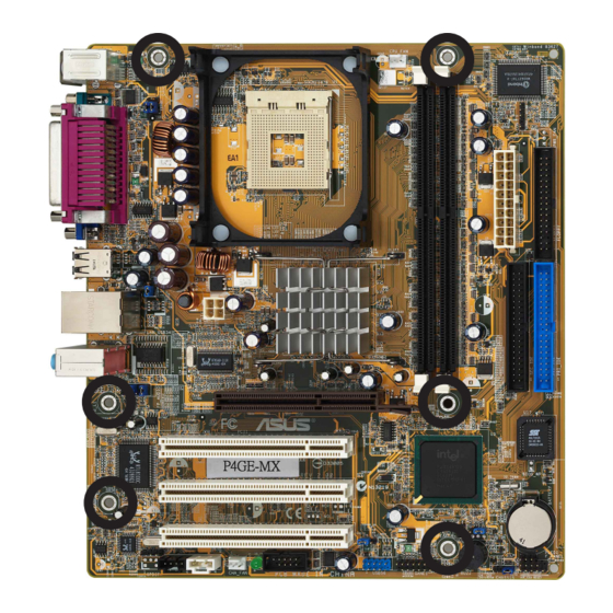
Place six (6) screws into the holes indicated by circles to secure the motherboard to the chassis. Do not overtighten the screws! Doing so may damage the motherboard. Place this side towards the rear of the chassis ASUS P4GE-MX motherboard... -
Page 18: Central Processing Unit (Cpu)
Gold Arrow ® P4GE-MX P4GE-MX CPU Socket 478 Incorrect installation of the CPU into the socket may bend the pins and severely damage the CPU! ® Notes on Intel Hyper-Threading Technology ®... -
Page 19: Installing The Cpu
CPU! 5. When the CPU is in place, push down the socket lever to secure the CPU. The lever clicks on the side tab to indicate that it is locked. ASUS P4GE-MX motherboard... -
Page 20: System Memory
104 Pins ® P4GE-MX P4GE-MX 184-Pin DDR DIMM Sockets Make sure to unplug the power supply before adding or removing DIMMs or other system components. Failure to do so may cause severe damage to both the motherboard and the components. -
Page 21: Expansion Slots
When using PCI cards on shared slots, ensure that the drivers support “Share IRQ” or that the cards do not need IRQ assignments. Otherwise, conflicts will arise between the two PCI groups, making the system unstable and the card inoperable. ASUS P4GE-MX motherboard 1-11... -
Page 22: Pci Slots
AGP card, make sure that you ask for one with +1.5V specification. Note the notches on the card golden fingers to ensure that they fit the AGP slot on the motherboard. Install only +1.5V AGP cards. ® P4GE-MX Keyed for 1.5v P4GE-MX Accelerated Graphics Port (AGP) 1-12 Chapter 1: Product introduction... -
Page 23: Jumpers
Clear CMOS Normal (Default) P4GE-MX Clear RTC RAM You do not need to clear the RTC when the system hangs due to overclocking. For system failure due to overclocking, use the C.P.R. (CPU Parameter Recall) feature. Shut down and reboot the system so BIOS can automatically reset parameter settings to its previous values. - Page 24 USBPWR_56 ® P4GE-MX +5VSB (Default) P4GE-MX USB device wake up • The USB device wake-up feature requires a power supply that can provide 500mA on the +5VSB lead for each USB port. Otherwise, the system would not power up. •...
-
Page 25: Connectors
9. VGA port. This port connects to a VGA monitor. 10. Serial connector. This port connects to your serial mouse and other serial devices. 11. PS/2 keyboard port. This purple connector is for a PS/2 keyboard. ASUS P4GE-MX motherboard 1-15... -
Page 26: Internal Connectors
(Pin 5 is removed to prevent incorrect insertion when using ribbon cables with pin 5 plug). FLOPPY1 NOTE: Orient the red markings on the floppy ribbon cable to PIN 1. ® P4GE-MX PIN 1 P4GE-MX Floppy disk drive connector 1-16 Chapter 1: Product introduction... - Page 27 -12.0VDC +3.3VDC +3.3VDC P4GE-MX ATX power connectors Make sure that your ATX 12V power supply can provide 8A on the +12V lead and at least 1A on the +5-volt standby lead (+5VSB). The minimum recommended wattage is 230W, or 300W for a fully configured system. The system may become unstable and may experience difficulty powering up if the power supply is inadequate.
- Page 28 USB 2.0 ports for connecting next generation USB peripherals such as high resolution cameras, scanners, and printers. ® P4GE-MX USB56 P4GE-MX USB 2.0 connector • The USB 2.0 module is purchased separately. • Install the USB 2.0 driver before using the USB 2.0 feature.
- Page 29 FP_AUDIO ® P4GE-MX P4GE-MX Front panel audio connector 8. Chassis intrusion connector (4-1 pin CHASSIS1) This lead is for a chassis designed with intrusion detection feature. This requires an external detection mechanism such as a chassis intrusion sensor or microswitch.
- Page 30 This connector is for the S/PDIF audio module to allow digital sound output. Connect one end of the S/PDIF audio cable to this connector and the other end to the S/PDIF module. ® P4GE-MX SPDIF_OUT P4GE-MX Digital audio connector The S/PDIF out module is purchased separately. 1-20 Chapter 1: Product introduction...
- Page 31 PIN 1 COM2 ® P4GE-MX P4GE-MX Serial port connector The COM2 bracket is purchased separately. 12. Power LED connector (3-pin PLED1 ) This 3-pin connector connects to a 3-pin system power LED. The LED lights up when you turn on the system power.
- Page 32 ® P4GE-MX IDE_LED Reset P4GE-MX Front panel audio connector • System Power LED Lead (2-pin PLED) This 2-pin connector connects to the system power LED. The LED lights up when you turn on the system power. • ATX Power Switch / Soft-Off Switch Lead (2-pin PWR) This connector connects a switch that controls the system power.
-
Page 33: Chapter 2: Bios Information
Chapter 2 This chapter tells how to change system settings through the BIOS Setup menus. Detailed descriptions of the BIOS parameters are also provided. BIOS information ASUS P4GE-MX motherboard... -
Page 34: Managing And Updating Your Bios
Input/Output System (BIOS) setup. 1. AwardBIOS Flash Utility (EZ Flash feature that updates the BIOS using a floppy disk during POST.) 2. ASUS CrashFree BIOS (Updates the BIOS using a bootable floppy disk when the BIOS gets corrupted.) ® 3. ASUS Update (Updates the BIOS in Windows environment.) -
Page 35: Updating The Bios With Ez Flash Feature
Save only the updated BIOS file in the floppy disk to avoid loading a wrong BIOS file. 1. Download the latest BIOS file from the ASUS website (www.asus.com). Rename the file to *.BIN and save it to the bootable floppy disk you created earlier. -
Page 36: Recovering The Bios With Crashfree Bios
3. Insert a floppy disk that contains the original or the latest BIOS file for this motherboard. If all the necessary files are found in the floppy disk, the BIOS update process continues. Make sure that the BIOS file in the floppy disk is renamed as “P4GE-MX.ROM”. Chapter 2: BIOS information... -
Page 37: To Recover The Bios From The Support Cd
2. When the BIOS update process is complete, reboot the system. The recovered BIOS may not be the latest BIOS version for this motherboard. Visit ASUS website (www.asus.com) to download the latest BIOS file. ASUS P4GE-MX motherboard... -
Page 38: Asus Update
2.1.4 ASUS Update The ASUS Update is a utility that allows you to update the motherboard BIOS in ® Windows environment. This utility is available in the support CD that comes with the motherboard package. ASUS Update requires an Internet connection either through a network or an Internet Service Provider (ISP). - Page 39 If you selected the option to update the BIOS from a file, a window pops up prompting you to locate the file. Select the file, click Save, then follow the screen instructions to complete the update process. ASUS P4GE-MX motherboard...
-
Page 40: Bios Setup Program
BIOS Setup program This motherboard supports a programmable firmware hub (FHW) chip that you can update using the provided utility described in section “2.1 Managing and updating your BIOS.” Use the BIOS Setup program when you are installing a motherboard, reconfiguring your system, or prompted to “Run Setup”. -
Page 41: Bios Menu Screen
• The BIOS setup screens shown in this chapter are for reference purposes only, and may not exactly match what you see on your screen. • Visit the ASUS website (www.asus.com) to download the latest BIOS information. ASUS P4GE-MX motherboard... -
Page 42: Legend Bar
2.2.3 Legend bar At the bottom of the Setup screen is a legend bar. The keys in the legend bar allow you to navigate through the various setup menus. The following table lists the keys found in the legend bar with their corresponding functions. Navigation Key Function <F1>... -
Page 43: Main Menu
This field requires users to enter the password before entering the BIOS setup or the system. Select [Setup] to require the password before entering the BIOS Setup. Select [System] to require the password before entering the system. Configuration options: [Setup] [System] ASUS P4GE-MX motherboard 2-11... - Page 44 Supervisor Password [Clear] / User Password [Clear] These fields allow you to set passwords. To set a password, highlight the appropriate field and press <Enter>. Type in a password then press <Enter>. You can type up to eight alphanumeric characters. Symbols and other characters are ignored.
-
Page 45: Primary And Secondary Master/Slave
Refer to the drive documentation or the drive label for this information. To enter a value, you may also highlight the item, then press <Enter> to display a pop-up menu. Type in the value from the drive documentation, then press <Enter>. ASUS P4GE-MX motherboard 2-13... - Page 46 Before attempting to configure a hard disk drive, make sure you have the correct configuration information supplied by the drive manufacturer. Incorrect settings may cause the system to fail to recognize the installed hard disk. Capacity [xxxxx MB] This item displays the auto-detected hard disk capacity. The value is not user-configurable.
-
Page 47: Advanced Menu
Sets the latency between the DRAM command and the time the data actually become available. Configuration options: [1.5] [2] [2.5] [3] Active to Precharge Delay [7] Controls the number of DRAM clocks used for the DRAM parameters. Configuration options: [7] [6] [5] ASUS P4GE-MX motherboard 2-15... - Page 48 DRAM RAS# to CAS# Delay [3] Sets the latency between the DRAM active command and the R/W command. Configuration options: [3] [2] DRAM RAS# Precharge [3] Sets the idle clocks after issuing a precharge command to the DRAM. Configuration options: [3] [2] Memory Frequency for [Auto] This item allows you set the FSB and system memory frequency.
-
Page 49: Integrated Peripherals
Secondary Master PIO [Auto] Secondary Slave PIO [Auto] These items allow you to set a PIO (Programmable Input/Output) mode for primary IDE devices. Configuration options: [Auto] [Mode 0] [Mode 1] [Mode 2] [Mode 3] [Mode 4] ASUS P4GE-MX motherboard 2-17... - Page 50 On-Chip Secondary PCI IDE [Enabled] Disables or enables the On-chip Secondary PCI IDE support. Configuration options: [Disabled] [Enabled] Primary Master UDMA [Auto] Primary Slave UDMA [Auto] Secondary Master UDMA [Auto] Secondary Slave UDMA [Auto] These items allow you to automatically set or disable the primary IDE UDMA capability, which improves transfer speeds and data integrity for compatible IDE devices.
- Page 51 Allows you to enable or disable the onboard LAN controller. Configuration options: [Disabled] [Enabled] Onboard LAN Boot ROM [Disabled] Allows you to enable or disable the boot ROM of the onboard LAN chip. Configuration options: [Disabled] [Enabled] ASUS P4GE-MX motherboard 2-19...
-
Page 52: Power Menu
Power menu ACPI Suspend Type [S1& S3] Allows you to select the ACPI state to used for system suspend. Configuration options: [S1 (POS)] [S3 (STR)] [S1 & S3] USB Device Wake-Up From S3 [Enabled] Disables or enables the USB device wake-up from S3 feature. Configuration options: [Disabled] [Enabled] POWER ON Function [BUTTON ONLY] Allows you to set a button or key to wake up the system. - Page 53 Configuration options: [Min=0] [Max=31] Time (hh:mm:ss) Alarm [0:0:0] To set the time of alarm: 1. Highlight this item and press <Enter> to display a pop-up menu for the hour field. 2. Key-in a value (Min=0, Max=23), then press <Enter>. ASUS P4GE-MX motherboard 2-21...
-
Page 54: Hardware Monitor
2. Key-in a value (Min=0, Max=23), then press <Enter>. 3. Press tab to move to the minutes field, then press <Enter>. 4. Key-in a minute value (Min=0, Max=59), then press <Enter>. 5. Press tab to move to the seconds field, the press <Enter>. 6. -
Page 55: Boot Menu
This allows you to enable or disable the full screen logo display feature. Configuration options: [Disabled] [Enabled] Make sure that the Full Screen Logo Show item is set to [Enabled] if you wish to use the ASUS MyLogo™ feature. ASUS P4GE-MX motherboard 2-23... -
Page 56: Exit Menu
Exit menu Save & Exit Setup Once you are finished making your selections, choose this option from the Exit menu to ensure the values you selected are saved to the CMOS RAM. The CMOS RAM is sustained by an onboard backup battery and stays on even when the PC is turned off. -
Page 57: Chapter 3: Software Support
Chapter 3 This chapter describes the contents of the support CD that comes with the motherboard package. Software support... -
Page 58: Install An Operating System
The contents of the support CD are subject to change at any time without notice. Visit the ASUS website for updates. 3.2.1 Running the support CD To begin using the support CD, simply insert the CD into your CD-ROM drive. The CD automatically displays the Drivers menu if Autorun is enabled in your computer. -
Page 59: Drivers Menu
LAN driver. ® ® For Windows XP users, make sure to install Windows XP Service Pack 1 to support USB 2.0. 3.2.3 Utilities menu The Utilities menu shows the applications and other software that the motherboard supports. ASUS P4GE-MX motherboard... -
Page 60: Asus Contact Information
ASUS Update This program allows you to download the latest version of the BIOS from the ASUS website. Before using the ASUS Update, make sure that you have an Internet connection so you can connect to the ASUS website. Installing ASUS Update also installs ASUS Mylogo™. -
Page 61: Audio Configuration
The connector sensing feature allows you to check if your audio devices are connected properly. Click the the Connector Sensing tab to display the details. Click the Option button to change sensing options. Click the Start button to start connection sensing. ASUS P4GE-MX motherboard... - Page 62 The Realtek ® EZ-connection dialog box shows your current audio connections. The text at the bottom of the box explains your audio connection status. An X mark denotes an incorrect connection. If there are detected problems, make sure that your audio cables are connected to the proper audio jack and repeat connector sensing.