
Related Manuals for Asus P4G800-V


Summary of Contents for Asus P4G800-V
- Page 1 ® P4G800-V...
-
Page 5: Federal Communications Commission Statement
Federal Communications Commission Statement This device complies with FCC Rules Part 15. Operation is subject to the following two conditions: • This device may not cause harmful interference, and • This device must accept any interference received including interference that may cause undesired operation. This equipment has been tested and found to comply with the limits for a Class B digital device, pursuant to Part 15 of the FCC Rules. - Page 8 viii...
- Page 9 ® ® ® ®...
- Page 12 ® ® ® ® ® ® ®...
- Page 13 ® ®...
- Page 15 ® ® ® ®...
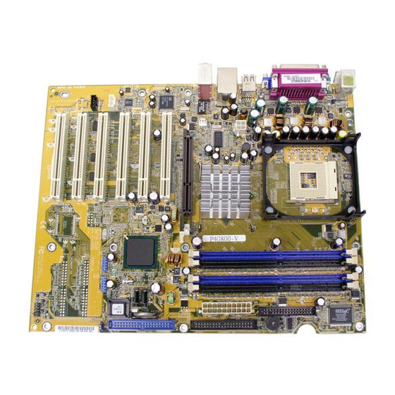
- Page 17 24.5cm (9.6in) PS/2 T: Mouse B: Keyboard Socket 478 CPU_FAN1 COM1 USB12 Bottom: ATX12V1 Top: USB3 RJ-45 USB4 Top:Line In Center:Line Out Below:Mic In CHA_FAN1 Accelerated Graphics Port PCI 1 Realtek RTL8101L Intel PCI 2 ICH5 Audio PCI 3 Codec BIOS PCI 4 AUX IN...
- Page 20 ® ® ® ® 1-10...
- Page 21 90 - 100 1-11...
- Page 22 104 Pins 80 Pins P4G800-V 184-Pin DDR DIMM Sockets 1-12...
- Page 23 800 MHz PC3200/PC2700*/PC2100 400/333*/266 MHz 533 MHz PC2700/PC2100 333/266 MHz 400 MHz PC2100 266 MHz 1-13...
- Page 24 256MB Apacer 77.10636.465 SAMSUNG SS K4H560838D-TCC4 256MB SAMSUNG M368L3223ETM-CCC SAMSUNG SS K4H560838E-TCCC 256MB Winbond W9425GCDB-5 Winbond SS W942508CH-5 512MB AG32L64T8SQC4S SAMSUNG DS K4H560838D-TCC4 128MB NANYA NT128D64SH4b1G-5T NANYA SS NT5DS16M16BT-5T 256MB TwinMos M2G9I08AFATT9F081AA4T TwinMos SS TMD7608F8E50D 128MB Infineon HYS64D16301GU-5-B Infineon SS HYB25D256160BT-5B 1-14...
- Page 25 USB 2.0 ì IRQî 1-15...
- Page 26 P4G800-V Accelerated Graphics Port (AGP) 1-16...
- Page 27 1 2 3 1 2 3 Clear CMOS Normal (Default) P4G800-V Clear RTC RAM 1-17...
- Page 28 FLOPPY NOTE: Orient the red markings on the floppy ribbon cable to PIN 1 PIN 1 P4G800-V Floppy Disk Drive Connector P4G800-V SATA Connectors 1-18...
- Page 29 NOTE: Orient the red markings (usually zigzag) on the IDE ribbon cable to PIN 1. PIN 1 P4G800-V IDE Connectors PIN 1 1-19...
- Page 30 ATX12V1 ATXPWR1 +12.0VDC +5.0VDC +12V DC +12V DC +5VSB +5.0VDC PWR_OK -5.0VDC +5.0VDC +5.0VDC PS_ON# +3.3VDC -12.0VDC +3.3VDC +3.3VDC P4G800-V ATX Power Connector CPU_FAN1 CHA_FAN1 +12V Rotation P4G800-V 12-Volt Cooling Fan Power 1-20...
- Page 31 AUX IN(White) CD IN (Black) P4G800-V Internal Audio Connectors USB2 USB1 P4G800-V USB 2.0 Header 1-21...
- Page 32 ATX Power Power LED Switch* HPANEL1 HDLED Reset SW P4G800-V Front Panel Audio Connector 1-22...
- Page 35 A:\>afudos /ip4g800v.rom AMI Firmware Update Utility - Version 1.10 Copyright (C) 2002 American Megatrends, Inc. All rights reserved. Reading file ..done Erasing flash ..done Writing flash ..0x0008CC00 (9%) A:\>afudos /ip4g800v.rom AMI Firmware Update Utility - Version 1.10 Copyright (C) 2002 American Megatrends, Inc.
- Page 36 User recovery requested. Starting BIOS recovery... Checking for floppy... User recovery requested. Starting BIOS recovery... Checking for floppy... Floppy found! Reading file “p4g800v.rom”. Completed. Start flashing... Flashed successfully. Rebooting.
- Page 38 Legacy Diskette A [1.44M, 3.5 in] select a field. Primary IDE Master :[ST320413A] Use [+] or [-] to Primary IDE Slave :[ASUS CD-S340] configure system time. Secondary IDE Master :[Not Detected] Secondary IDE Slave :[Not Detected] Third IDE Master :[Not Detected]...
- Page 39 Legacy Diskette A [1.44M, 3.5 in] select a field. Primary IDE Master :[ST320413A] Use [+] or [-] to Primary IDE Slave :[ASUS CD-S340] configure system time. Secondary IDE Master :[Not Detected] Secondary IDE Slave :[Not Detected] Third IDE Master :[Not Detected]...
- Page 40 Legacy Diskette A [1.44M, 3.5 in] select a field. Primary IDE Master :[ST320413A] Use [+] or [-] to Primary IDE Slave :[ASUS CD-S340] configure system time. Secondary IDE Master :[Not Detected] Secondary IDE Slave :[Not Detected] Third IDE Master :[Not Detected]...
- Page 41 Primary IDE Master Select the type Device : Hard Disk of device connected Vendor : ST320413A to the system. Size : 20.0GB LBA Mode : Supported Block Mode : 16 Sectors PIO Mode Async DMA : MultiWord DMA-2 Ultra DMA : Ultra DMA-5 SMART Monitoring: Supported [Auto]...
- Page 42 IDE Configuration Onboard IDE Operate Mode [Enhanced Mode] Enhanced Mode Support On [S-ATA] IDE Detect Time Out (Sec) [35] Select Screen Select Item Change Option General Help Save and Exit Exit 2-10...
- Page 43 2-11...
- Page 44 AMI BIOS Version : 08.00.09 Build Date : 05/27/03 Processor Type : Intel(R) Pentium(R) 4 CPU 2.53GHz Speed : 2530 MHz Count System Memory Size : 256MB Select Screen Select Item Change Option General Help Save and Exit Exit 2-12...
- Page 45 CPU Configuration Configure CPU. Chipset Onboard Devices Configuration PCI PnP USB Configuration Select Screen Select Item Enter Go to Sub-screen General Help Save and Exit Exit Configure advanced CPU settings Manufacturer : Intel(R) Brand String : Intel(R) Pentium(R) 4 CPU 2.53GHz Frequency : 2530 MHz Ratio Status...
- Page 46 Advanced Chipset settings Set the CPU external frequency for next WARNING: Setting wrong values in the sections below boot. may cause system to malfunction. Configure DRAM Timing by SPD [Enabled] Graphic Adapter Priority [AGP/Int. VGA] Onboard Video Memory [Enabled, 8MB] Graphics Aperture Size [ 64 MB] Spread Spectrum...
- Page 47 2-15...
- Page 48 OnBoard Audio [Auto] OnBoard LAN [Enabled] OnBoard LAN Boot ROM [Disabled] Serial Port1 Address [3F8/IRQ4] Parallel Port Address [378] Parallel Port Mode [ECP] ECP Mode DMA Channel [DMA3] Parallel Port IRQ [IRQ7] Select Screen Select Item Change Option General Help Save and Exit Exit 2-16...
- Page 49 2-17...
- Page 50 Advanced PCI/PnP settings NO: Lets the bIOS configure all the WARNING: Setting wrong values in the sections below devices in the system. may cause system to malfunction. YES: Lets the Plug and Play OS [No] operating system PCI Latency Timer [64] configure Plug and Allocate IRQ to PCI VGA...
- Page 51 2-19...
- Page 52 USB Configuration Enables USB host controllers. Module Version : 2.22.4-5.3 USB Devices Enabled : None USB Function [8 USB Ports] Legacy USB Support [Auto] USB 2.0 Controller [Enabled] USB 2.0 Controller Mode [HiSpeed] USB Mass Storage Device Configuration Select Screen Select Item Change Option General Help...
- Page 53 USB Mass Storage Device Configuration Number of seconds POST waits for the USB USB Mass Storage Reset Delay [20 Sec] mass storage device after that start unit No USB Mass Storage device detected command. Device #1 Emulation Type [N/A] Device #2 Emulation Type [N/A] Device #3...
- Page 54 Suspend Mode [Auto] Configure CPU. Repost Video on S3 Resume [No] ACPI 2.0 Support [No] ACPI APIC Support [Enabled] BIOS -> AML ACPI table [Enabled] APM Configuration Hardware Monitor Select Screen Select Item Enter Go to Sub-screen General Help Save and Exit Exit 2-22...
- Page 55 APM Configuration Enabled or disable APM. Power Management/APM [Enabled] Video Power Down Mode [Suspend] Hard Disk Power Down Mode [Suspend] Suspend Time Out [Disabled] Throttle Slow Clock Ratio [50%] System Thermal [Disabled] Power Button Mode [On/Off] Restore on AC Power Loss [Power Off] Select Screen Resume on RTC Alarm...
- Page 56 2-24...
- Page 57 Hardware Monitor CPU temperature CPU Temperature [44°C/111°F] MB Temperature [36°C/96.5°F] CPU Fan Speed [2250RPM] Chassis Fan Speed [XXX RPM] VCORE Voltage [1.550V] 3.3V Voltage [3.386V] 5V Voltage [4.890V] 12V Voltage [11.900V] Select Screen Select Item Change Option General Help Save and Exit Exit 2-25...
- Page 58 Specifies the boot sequence from the 1st Boot Device [First Floppy Drive] available devices. 2nd Boot Device [PM-ST320413A] 3rd Boot Device [PS-ASUS CD-S340] A device enclosed in parenthesis has been disabled in the corresponding type menu. Select Screen Select Item...
- Page 59 Boot Settings Configuration Allows BIOS to skip certain tests while Quick Boot [Enabled] booting. This will Full Screen Logo [Enabled] decrease the time Add On ROM Display Mode [Force BIOS] needed to boot the Bootup Num-Lock [On] system. PS/2 Mouse Support [Auto] Typematic Rate [Fast]...
- Page 60 Security Settings <Enter> to change password. Supervisor Password Not Installed <Enter> again to User Password Not Installed disable password. Change Supervisor Password Boot Sector Virus Protection [Disabled] Select Screen Select Item Change Option General Help Save and Exit Exit 2-28...
- Page 61 Security Settings <Enter> to change password. Supervisor Password Installed <Enter> again to User Password Not Installed disable password. Change Supervisor Password User Access Level [Full Access] Change User Password Clear User Password Password Check [Setup] Boot Sector Virus Protection [Disabled] Select Screen Select Item Change Option...
- Page 62 2-30...
- Page 63 Exit Options Exit system setup after saving the Exit & Save Changes changes. Exit & Discard Changes Discard Changes F10 key can be used for this operation. Load Setup Defaults Select Screen Select Item Enter Go to Sub-screen General Help Save and Exit Exit 2-31...
- Page 64 2-32...
- Page 67 ® ®...