Sony MZ-R70 Service Manual
Service manual
Hide thumbs
Also See for MZ-R70:
- Operating instructions manual (152 pages) ,
- Specification sheet (2 pages) ,
- Limited warranty (1 page)
Table of Contents
Advertisement
SERVICE MANUAL
Ver 1.3 2001. 01
With SUPPLEMENT-1
(9-927-631-81)
US and foreign patents licensed from Dolby
Laboratories Licensing Corporation.
System
Audio playing system
MiniDisc digital audio system
Laser diode properties
Material: GaAlAs
Wavelength: = 790 nm
Emission duration: continuous
Laser output: less than 44.6 W
(This output is the value measured at a
distance of 200 mm from the lens surface
on the optical pick-up block with 7 mm
aperture.)
Recording and playback time
Maximum 80 minutes (MDW-80, stereo
recording)
Maximum 160 minutes (MDW-80,
monaural recording)
Maximum 74 minutes (MDW-74, stereo
recording)
Maximum 148 minutes (MDW-74,
monaural recording)
Revolutions
400 rpm to 1,800 rpm (CLV)
Error correction
Advanced Cross Interleave Reed Solomon
Code (ACIRC)
Sampling frequency
44.1 kHz
Sampling rate converter
Input: 32 kHz/44.1 kHz/48 kHz
Coding
Adaptive TRansform Acoustic Coding
(ATRAC)
Modulation system
EFM (Eight to Fourteen Modulation)
Number of channels
2 stereo channels
1 monaural channel
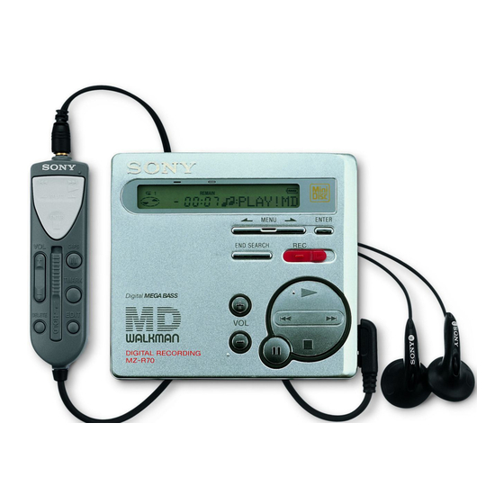
(Photo: Silver)
Model Name Using Similar Mechanism
Mechanism Type
Optical Pick-up Name
SPECIFICATIONS
Frequency response
20 to 20,000 Hz ± 3 dB
Wow and Flutter
Below measurable limit
Inputs
Microphone: stereo mini-jack, 0.35–1.38
mV
Line in: stereo mini-jack, 69–194 mV
Optical (Digital) in: optical (digital) mini-
jack
Outputs
i1: stereo mini-jack, maximum output
level 5 mW + 5 mW, load impedance 16
ohm
i2: stereo mini-jack, maximum output
level 5 mW + 5 mW, load impedance 16
ohm
General
Power requirements
Sony AC Power Adaptor (supplied)
connected at the DC IN 3 V jack:
120 V AC, 60 Hz (US model)
230-240 V AC, 50/60 Hz (UK and Hong
Kong model)
240 V AC, 50/60 Hz (Australia and New
Zealand model)
220-230 V AC, 50/60 Hz (European
model)
220 V AC, 50 Hz (China model)
220 V AC, 50 Hz (Argentina model)
100-240 V AC, 50/60 Hz (Other models)
PORTABLE MINIDISC RECORDER
– 1 –
MZ-R70
US Model
Canadian Model
AEP Model
UK Model
Australian Model
Chinese Model
Tourist Model
MZ-R90/R91
MT-MZR70-165
LCX-2R
Nickel cadmium rechargeable battery
NC-WMAA (supplied)
LR6 (size AA) alkaline battery (not
supplied)
Battery operation time
Battery life
1)
Batteries
Recording
NC-WMAA
Approx.
nickel cadmium
3 hours
rechargeable
battery
LR6 (size AA)
Approx.
Sony alkaline
3 hours
dry battery
1)
The battery life may be shorter due to
operating conditions and the temperature
of the location.
2)
When you record, use a fully charged
rechargeable battery.
3)
Recording time may differ according to
the alkaline batteries.
– Continued on next page –
E Model
Playback
2)
Approx.
6.5 hours
Approx.
17 hours
3)
Advertisement
Table of Contents

Related Manuals for Sony MZ-R70


Summary of Contents for Sony MZ-R70
- Page 1 When you record, use a fully charged Maximum 148 minutes (MDW-74, Power requirements rechargeable battery. monaural recording) Sony AC Power Adaptor (supplied) Recording time may differ according to Revolutions connected at the DC IN 3 V jack: the alkaline batteries.
- Page 2 DIAGRAMMES SCHÉMATIQUES ET LA LISTE DES PIÈCES SONT CRITIQUES POUR LA SÉCURITÉ DE FONCTIONNEMENT. NE REMPLACER CES COMPOSANTS QUE PAR DES PIÈCES SONY DONT LES NUMÉROS SONT DONNÉS DANS CE MANUEL OU DANS LES SUPPLÉMENTS PUBLIÉS PAR SONY. – 2 –...
-
Page 3: Table Of Contents
TABLE OF CONTENTS 1. SERVICING NOTE 5. ELECTRICAL ADJUSTMENTS ............4 ......20 5-1. Outline ................. 20 5-2. Precautions for Adjustment ..........20 2. GENERAL ................. 5 5-3. Adjustment Sequence ............20 Looking at the Controls ............5 5-4. NV Reset ................20 Recording an MD Right Away! .......... -
Page 4: Servicing Note
SECTION 1 SERVICING NOTE • When repairing this device with the power on, if you remove NOTES ON HANDLING THE OPTICAL PICK-UP the MAIN board or open the upper panel assy, this device stops BLOCK OR BASE UNIT working. The laser diode in the optical pick-up block may suffer electro- In this case, you can work without the device stopping by fas- static break-down because of the potential difference generated tening the hook of the open/close detect switch (S801) with tape. -
Page 5: General
SECTION 2 GENERAL This section is extracted from instruction manual. – 5 –... - Page 6 – 6 –...
- Page 7 – 7 –...
-
Page 8: Disassembly
SECTION 3 DISASSEMBLY Note : This set can be disassemble according to the following sequence. Block Assy, Bottom Panel Block Assy, Upper LCD Module Main Board MD Mechanism Deck Service Assy, OP Holder Assy Motor Flexible Board Motor, DC (M602) “Motor, DC (M601)”, “Motor, DC (M603)”... -
Page 9: Lcd Module
3-3. LCD MODULE 1 screws (1.7) 3 LCD module claws 3-4. MAIN BOARD 4 screw (1.4) 8 screw (1.7) 1 CN601 0 claws 6 screws (1.7) 7 stay 5 screw (1.4) qf MAIN board 9 claws 3 Remove the solder. qa boss 2 CN602 qd CN501... -
Page 10: Md Mechanism Deck
3-5. MD MECHANISM DECK (MT-MZR70-165) 5 MD mechanism deck 3 boss (MT-MZR70-165) 4 boss chassis assy 2 screw (1.4) 1 screw (1.4) 3-6. SERVICE ASSY, OP 1 washer (0.8 - 2.5) 3 precision pan screw (M1.4) 2 gear (SA) 8 Pull off the lead screw. 4 rack spring 6 screw 5 screw... -
Page 11: Holder Assy
3-7. HOLDER ASSY 5 Remove the holder assy to direction of the arrow C. 1 Open the holder assy. 2 Push the convex portion toward the direction B and open the holder assy toward the direction A to erect uprightly. 4 boss 3-8. -
Page 12: Motor, Dc (M602)
3-9. MOTOR, DC (M602) 1 Remove four solders of motor flexible board. 2 washer (0.8 - 2.5) 4 two precision pan screws (M1.4) 3 gear (SA) 5 DC motor (sled) (M602) 3-10. “MOTOR, DC (M601)”, “MOTOR, DC (M603)” 1 Remove six solders of motor flexible board. -
Page 13: Test Mode
SECTION 4 TEST MODE 4-1. OUTLINE 2 In the normal mode, turn on the HOLD switch on the set. While pressing the key on the set, press the following remote • This set provides the Overall adjustment mode (Assy mode) that control keys in the following order: allows CD and MO disc to be automatically adjusted when in the test mode. -
Page 14: Manual Mode
4-2-4. Configuration of Test Mode [VOL +] key:100th place of mode number [Major item switching] increase. [Test Mode $Display Check Mode%] [VOL --] key:100th place of mode number [VOL +] Press the > decrease. [Manual Mode] Press the [VOL +] [Servo Mode] key:10th place of mode number [Medium item switching]... -
Page 15: Overall Adjustment Mode
4-4. OVERALL ADJUSTMENT MODE 5. The display changes a shown below each time the jog key on [DISPLAY] the set is turned up or key on the remote com- Mode to adjust the servo automatically in all items. mander is pressed. Normally, automatic adjustment is executed in this mode at the repair. -
Page 16: Sound Skip Check Result Display Mode
[REC] 4-5. SOUND SKIP CHECK RESULT DISPLAY MODE 4. When key on the set is pressed, the total of error count is displayed on the LCD, and each time the key is pressed, > This set can display and check the error count occurring during the error count descents one by one as shown below. -
Page 17: Self-Diagnosis Display Mode
4-6. SELF-DIAGNOSIS DISPLAY MODE This set uses the self-diagnosis system in which if an error oc- curs in recording/playback mode, the error is detected by the model control and power control blocks of the microprocessor and information on the cause is stored as history in EEPROM. By viewing this history in test mode, it helps you to analyze a fault and determine its location. - Page 18 • Description of Indication History History code number Description 1st0 The first error 1st1 Total recording time when 1st0 was generated (Higher rank byte) 1st2 Total recording time when 1st0 was generated (Lower rank byte) The last error Total recording time when N 0 was generated (Higher rank byte) Total recording time when N 0 was generated (Lower rank byte) N-10 One error before the last.
-
Page 19: Key Check Mode
4-7. KEY CHECK MODE This set can check if the set and remote commander function nor- mally. • Setting Method of Key Check Mode 1. Setting the test mode. (See page 13) [T MARK] [DISPLAY] 2. Press the key on the remote com- mander for several seconds activates the key check mode where all segments of LCD turn OFF. -
Page 20: Electrical Adjustments
3. Press the X key once more. • Test CD disc TDYS-1 (Part No. : 4-963-646-01) LCD display • SONY MO disc available on the market R e s * * * • Laser power meter LPM-8001 (Part No. : J-2501-046-A) •... - Page 21 • Adjustment method of VC PWM Duty (L) • Adjustment method of VC PWM Duty (H) (mode number: 762) (mode number: 765) 1. Select the manual mode of the test mode, and set the mode 1. Select the manual mode of the test mode, and set the mode number 762.
-
Page 22: Temperature Correction
Outward ON CD focus bias adjustment When power adjustment “L” finished; Inward ON 8. If CD adjustment is OK, insert an available SONY MO disc Power supply is not yet adjusted unless both outward (recorded). and inward disc marks are ON. -
Page 23: Laser Power Check
5-8. LASER POWER CHECK • Overall MO adjustment items Connection : Item No. Contents laser power meter MO electrical offset adjustment Optical pick-up objective lens Low reflective CD TE gain adjustment Low reflective CD TE offset adjustment digital voltmeter Low reflective CD ABCD level adjustment MAIN board Low reflective CD focus gain adjustment Between TP1001... - Page 24 Connecting Location: – MAIN BOARD (SIDE A) – TP5105 TP914 TP915 – MAIN BOARD (SIDE B) – TP1001 TP1002 R1005 – 24 –...
-
Page 25: Diagrams
MZ-R70 SECTION 6 DIAGRAMS 6-1. BLOCK DIAGRAM — MD SECTION — DIGITAL SERVO SIGNAL PROCESSOR OPTICAL PICK-UP BLOCK RF AMP, FOCUS/TRACKING ERROR AMP EFM/ACIRC DECODER (LCX-2R) IC501 SHOCK PROOF MEMORY CONTROLLER ATRAC DECODER IC502 (1/2) XRST DADT DADT PEAK JX JY... -
Page 26: Block Diagram - Audio Section
MZ-R70 6-2. BLOCK DIAGRAM — AUDIO SECTION — CONTROL Q302 J301 LINE IN (OPTICAL) DIGITAL SIGNAL PROCESSOR EFM/ACIRC ENCODER R-CH MIC AMP ATRAC ENCODER IC302 16M BIT DRAM A/D, D/A CONVERTER IC502 (2/2) IC301 REC DRIVE STBY IC603 LIN 2... -
Page 27: Block Diagram - Power Supply Section
MZ-R70 6-3. BLOCK DIAGRAM — POWER SUPPLY SECTION — (Page 25) • Waveforms TO PB 50mV/div, lµs/div (PB) SECTION Approx. 1.4Vp-p TO REC/AMP RMC KEY SECTION IC501 (FE), IC502 (FE) (Page 28) SW & LCD MODULE UNIT 0.5V/div, 0.2µs/div (PB) -
Page 28: Printed Wiring Board - Main Board
MZ-R70 6-4. PRINTED WIRING BOARD — MAIN BOARD — Common note on Schematic Diagram: MAIN BOARD (SIDE A) • All capacitors are in µF unless otherwise noted. pF: µµF 50 WV or less are not indicated except for electrolytics and tantalums. - Page 29 MZ-R70 • Semiconductor MAIN BOARD (SIDE B) Location Ref. No. Location D101 F-10 D201 F-10 (D301) H-10 S806 (PROTECT) (D302) I-10 (D501) D600 D601 RECHARGEABLE BATTERY D602 NC-WMAA C937 (D901) 1.2V 700mAh (D902) (D903) D905 D906 D907 C938 (IC301) L602...
-
Page 30: Schematic Diagram - Main Board (1/3)
MZ-R70 6-5. SCHEMATIC DIAGRAM — MAIN BOARD (1/3) — • Refer to page 30 for Waveforms. • Refer to page 41 for IC Block Diagrams. (Page 38) – 35 – – 36 –... -
Page 31: Schematic Diagram - Main Board (2/3)
MZ-R70 6-6. SCHEMATIC DIAGRAM — MAIN BOARD (2/3) — • Refer to page 42, 43 for IC Block Diagrams. (Page 36) – 37 – – 38 –... -
Page 32: Schematic Diagram - Main Board (3/3)
MZ-R70 6-7. SCHEMATIC DIAGRAM — MAIN BOARD (3/3) — • Refer to page 41, 43 for IC Block Diagrams. – 39 – – 40 –... -
Page 33: Ic Block Diagrams
6-8. IC BLOCK DIAGRAM IC501 SN761056 ADIP S-MON A+B+C+D TWpp PK/BTM CSLO REXT VREF075 Aw+Dw Wpp-LPF S-MONITOR TON Peak VREF TON Botm Malfa ADIP AwBPF TEMP DwBPF Tpp/Wpp ABCD AVCC OFC-1 OFC-2 AGND RFOUT CCSL2 ABCD VREF075 PEAK PEAK/BOTM BOTM TON-C DGND OFTRK... - Page 34 IC601 MPC17A56FTA 35 34 30 29 26 25 PRE DRIVER PRE DRIVER HI-BRIDGE HI-BRIDGE CONTROL CONTROL CPWI CPVI CPUI PGNDW BIAS VMVW HI-BRIDGE HI-BRIDGE PGNDUV CONTROL CONTROL PRE DRIVER PRE DRIVER PRE DRIVER 3 PHASE CONTROL 9 10 11 12 IC603 MPC18A21MTB CONTROL LOGIC...
- Page 35 IC901 MPC18A31FTA 36 35 33 32 FFCLR SYSTEM CONTROL OSC2 STEP-UP STEP-UP PRE DRIVER PRE DRIVER XRST VSTL FFCLR VRMC XRST CRST INM1 RSTREF INM2 STEP-UP DC/DC CONVERTER SWVG VREG VREF BANDGAP REFERENCE PWMVC SERON CHGMON INM4 DCIN CHGB DCIN DCIN CHGSW 11 12...
-
Page 36: Ic Pin Descriptions
6-9. IC PIN DESCRIPTIONS • MAIN BOARD IC501 SN761056ADBT (RF AMP, FOCUS/TRACKING ERROR AMP) Pin No. Pin Name Pin Description Tracking error signal output to the CXD2660GA (IC502) REXT — Connected to the external resistor for the ADIP amplifier control WPPLPF —... - Page 37 • MAIN BOARD IC502 CXD2660GA (DIGITAL SIGNAL PROCESSOR, DIGITAL SERVO SIGNAL PROCESSOR, EFM/ACIRC ENCODER/DECODER, SHOCK PROOF MEMORY CONTROLLER, ATRAC ENCODER/DECODER, 16M BIT D-RAM) Pin No. Pin Name Pin Description VDC0 — Power supply terminal (+1.8 V) (for internal logic) MNT0 Not used (open) MNT1 Recording shock detect signal output to the system controller (IC801)
- Page 38 Pin No. Pin Name Pin Description VDIO1 — Power supply terminal (+2.4 V) (for I/O) VSIO1 — Ground terminal (for I/O) A00, A07, A10, 55 to 59 Address signal output to the external D-RAM Not used (open) A08, A09 XRAS Row address strobe signal output to the external D-RAM “L”...
- Page 39 Pin No. Pin Name Pin Description VDC4 — Power supply terminal (+1.8 V) (for internal logic) TRDR Tracking servo drive PWM signal (–) output to the MPC17A56FTA (IC601) TFDR Tracking servo drive PWM signal (+) output to the MPC17A56FTA (IC601) FFDR Focus servo drive PWM signal (+) output to the MPC17A56FTA (IC601) FRDR...
- Page 40 • MAIN BOARD IC801 CXR701080-010GA (SYSTEM CONTROLLER) Pin No. Pin Name Pin Description SYNC REC SYNCHRO REC switch (S801) input terminal “L”: off, “H”: on OFTRK Off track signal input from the CXD2660GA (IC502) Rec-proof claw detect input from the protect detect switch (S806) PROTECT “L”: recording possible, “H”: protect PAUSE KEY...
- Page 41 Pin No. Pin Name Pin Description System reset signal input from the MPC18A31FTA (IC901) “L”: reset XRST For several hundreds msec. after the power supply rises, “L” is input, then it changes to “H” — Ground terminal XTAL Main system clock output terminal (16.9344 MHz) EXTAL Main system clock input terminal (16.9344 MHz) —...
- Page 42 Pin No. Pin Name Pin Description SET KEY 2 Set key input terminal (A/D input) (B, jog, END SEARCH keys input) REC KEY REC key input terminal VRM MON VREM voltage monitor input terminal (A/D input) HIDC MON HI-DC voltage monitor input terminal (A/D input) AVSS —...
-
Page 43: Exploded Views
SECTION 7 EXPLODED VIEWS NOTE: • The mechanical parts with no reference • -XX and -X mean standardized parts, so The components identified by mark 0 or dotted line with mark number in the exploded views are not supplied. they may have some difference from the 0 are critical for safety. -
Page 44: Mechanism Deck Section
7-2. MECHANISM DECK SECTION (MT-MZR70-165) M602 @Note: No.74 washer is used for correction of the installation position of 601 (MOTOR). Certain sets do not have this washer. M601 M603 The components identified by Les composants identifiés par une mark 0 or dotted line with mark marque 0 sont critiques pour la 0 are critical for safety. -
Page 45: Electrical Parts List
SECTION 8 MAIN ELECTRICAL PARTS LIST NOTE: • Due to standardization, replacements in • Items marked “*” are not stocked since The components identified by mark 0 or dotted line with mark the parts list may be different from the they are seldom required for routine service. - Page 46 MAIN Ref. No. Part No. Description Remark Ref. No. Part No. Description Remark C526 1-164-943-11 CERAMIC CHIP 0.01uF C915 1-115-169-11 TANTALUM 10uF 6.3V C527 1-164-854-11 CERAMIC CHIP 15PF C916 1-110-569-11 TANTAL. CHIP 47uF C528 1-164-854-11 CERAMIC CHIP 15PF C917 1-128-964-11 TANTAL. CHIP 100uF 6.3V C529...
- Page 47 MAIN Ref. No. Part No. Description Remark Ref. No. Part No. Description Remark FB502 1-414-228-11 FERRITE BEAD INDUCTOR Q302 8-729-046-49 FET FDV304P FB503 1-414-228-11 FERRITE BEAD INDUCTOR Q501 8-729-928-81 TRANSISTOR DTC144EE FB504 1-414-228-11 FERRITE BEAD INDUCTOR Q601 8-729-046-43 FET HAT2051T-EL FB505 1-414-228-11 FERRITE BEAD INDUCTOR Q602...
- Page 48 MAIN Ref. No. Part No. Description Remark Ref. No. Part No. Description Remark R517 1-216-864-11 METAL CHIP 1/16W R908 1-216-844-11 METAL CHIP 1/16W R518 1-216-845-11 METAL CHIP 100K 1/16W R911 1-216-864-11 METAL CHIP 1/16W R519 1-216-821-11 METAL CHIP 1/16W R912 1-216-829-11 METAL CHIP 4.7K 1/16W...
- Page 49 MAIN Ref. No. Part No. Description Remark Ref. No. Part No. Description Remark < VIBRATOR > ACCESSORIES & PACKING MATERIALS ******************************** X501 1-781-725-21 VIBRATOR, CRYSTAL (22.5MHz) X801 1-781-575-21 VIBRATOR, CERAMIC (16.9344MHz) 1-418-028-11 ADAPTOR, AC (AC-MZR55) (E,JE) 1-418-049-11 ADAPTOR, AC (AC-MZR55) (UK,HK) ************************************************************* 1-418-275-11 ADAPTOR, AC (AC-MZR55) (US,CND) MISCELLANEOUS...
- Page 50 MZ-R70 Sony Corporation 2000B0425-1 9-927-631-12 Personal Audio Division Company Printed in Japan C2000. 2 – 58 – Published by General Engineering Dept.
- Page 51 Subject : Taiwan model Addition Taiwan model is added to the MZ-R70. This supplement-1 describes only differences from the MZ-R70 E model. Refer to the service manual for MZ-R70 (9-927-631-S) for other information. • ACCESSORIES & PACKING MATERIALS Page E model Taiwan model Ref.