HP T5730 - Compaq Thin Client Troubleshooting Manual
Thin client
Hide thumbs
Also See for T5730 - Compaq Thin Client:
- Quick setup and getting started manual (77 pages) ,
- Quickspecs (12 pages) ,
- Specification (12 pages)
Table of Contents
Advertisement
Quick Links
Advertisement
Table of Contents
Troubleshooting

Related Manuals for HP T5730 - Compaq Thin Client

Summary of Contents for HP T5730 - Compaq Thin Client
-
Page 1: Troubleshooting Guide
Troubleshooting Guide HP t5730/t5730w and t5735 Thin Client... - Page 2 © Copyright 2009 Hewlett-Packard Development Company, L.P. The information contained herein is subject to change without notice. Microsoft and Windows are trademarks of Microsoft Corporation in the U.S. and other countries. The only warranties for HP products and services are set forth in the express warranty statements accompanying such products and services.
-
Page 3: About This Book
About This Book WARNING! Text set off in this manner indicates that failure to follow directions could result in bodily harm or loss of life. CAUTION: Text set off in this manner indicates that failure to follow directions could result in damage to equipment or loss of information. - Page 4 About This Book...
-
Page 5: Table Of Contents
Table of contents 1 Product Description Operating systems ..........................1 Product features ........................... 1 Front Panel Components ..................... 2 Top Components ......................... 2 Rear Panel Components ..................... 4 Installing the Antenna (Wireless Models) ................4 Installing the Rubber Feet ....................5 Installing the Stand ...................... - Page 6 Setup Utility—Standard CMOS Features ................20 Setup Utility—Advanced BIOS Features ................20 Setup Utility—Integrated Peripherals ................. 21 Setup Utility—Power Management Setup ................. 22 Setup Utility—Utility Task Actions ..................22 5 Diagnostics and Troubleshooting LEDs ..............................23 Power-On Sequence .......................... 24 Power-On Diagnostic Tests ........................
- Page 7 Index ................................... 40...
- Page 8 viii...
-
Page 9: Product Description
Product Description HP has partnered with Altiris to manage HP Compaq thin clients. Altiris Deployment Solution is a leading- edge tool to help with quick deployment and for ongoing management of the thin clients in your organization. Each HP Compaq thin client is recognized by the Altiris Deployment Solution as a supported device. -
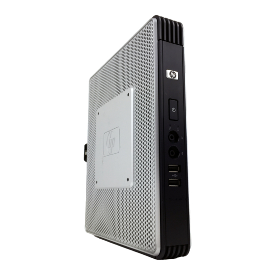
Page 10: Front Panel Components
Front Panel Components Secure USB compartment Power LED Power button Line-out (headphone) audio connector Flash activity LED Universal serial bus (USB) connectors (2) Line-in (microphone) Top Components Wireless antenna* Secure USB compartment Cable lock slot *Available on some models. Refer to the model-specific QuickSpecs at http://www.hp.com for details. - Page 11 Wireless antenna connector* Secure USB compartment ports (2) Cable lock slot *Available on some models. Refer to the model-specific QuickSpecs at http://www.hp.com for details. The wireless antenna allows you to send and receive wireless signals to communicate with wireless local area networks (WLAN). The secure USB compartment allows you to use two USB devices in a secured location.
-
Page 12: Rear Panel Components
Rear Panel Components Line-out audio connector Serial connector Ethernet RJ-45 connector DVI-D connector Universal serial bus (USB) connectors (4) VGA connector PS/2 connectors (2) Power connector For more information, see the model-specific QuickSpecs at http://h18004.www1.hp.com/products/quickspecs/ QuickSpecs_Archives/QuickSpecs_Archives.html. Installing the Antenna (Wireless Models) Screw the antenna in place on top of the thin client. -
Page 13: Installing The Rubber Feet
Installing the Rubber Feet To install the rubber feet: Locate the holes in the corners of the left side of the thin client. Remove the feet from their backing. Align the feet with their holes and press them in securely. Installing the Stand To install the stand: Turn unit upside down. -
Page 14: Serial Number Location
Turn unit upside down. Press the tab (1), and then slide the stand about 1.26 cm (1/2 inch) toward the front of the unit and lift the stand off the unit (2). Serial Number Location Every thin client includes a unique serial number located as shown in the following illustration. Have this number available when contacting HP customer service for assistance. -
Page 15: Hardware Changes
Hardware Changes General Hardware Installation Sequence To ensure the proper installation thin client hardware components: Back up any data, if necessary. If the thin client is powered on: Turn the unit and any other attached devices off. Disconnect the power cord from the wall outlet. Disconnect any external devices or cables, such as an antenna or cable lock. -
Page 16: Removing And Replacing The Secure Usb Compartment Cover
Replace the secure USB compartment cover. See Removing and Replacing the Secure USB Compartment Cover on page Reconnect any external devices and power cords. Turn on the monitor, the thin client, and any devices you want to test. Load any necessary drivers. NOTE: You can download select hardware drivers from HP at http://www.hp.com/country/us/eng/... -
Page 17: Installing The Usb Device
Remove the cover from the unit by first lifting the rear (screw side) of the cover, and then lifting the cover off the unit (3). Installing the USB Device Before beginning the replacement process, review General Hardware Installation Sequence on page 7 for procedures you should follow before and after installing or replacing hardware. -
Page 18: Removing And Replacing The Side Access Panel And Metal Side Cover
Replace the screw (3). Replace the antenna, if you are using one. Removing and Replacing the Side Access Panel and Metal Side Cover Removing the Side Access Panel and Metal Side Cover WARNING! Before removing the side access panel, ensure that the thin client is turned off and the power cord is disconnected from the electrical outlet. -
Page 19: Replacing The Metal Side Cover And Side Access Panel
NOTE: Do not remove the metal side cover when installing a PCI Expansion Module. You must remove the metal side cover to access internal components such as the battery or the memory. Remove the four screws that secure the metal side cover to the chassis (1). Lift the metal side cover, front side first, off the unit (2). -
Page 20: Removing And Replacing The Battery
Replace the screw that secures the access panel to the chassis (3). Removing and Replacing the Battery Before beginning the replacement process, review General Hardware Installation Sequence on page 7 for procedures you should follow before and after installing or replacing hardware. WARNING! Before removing the side access panel, ensure that the thin client is turned off and the power cord is disconnected from the electrical outlet. -
Page 21: Mounting The Thin Client
Mounting the Thin Client HP Quick Release The HP Compaq t5730/t5735 thin client incorporates four mounting points on each side of the unit. These mounting points follow the VESA (Video Electronics Standards Association) standard, which provides industry-standard mounting interfaces for Flat Displays (FDs), such as flat panel monitors, flat displays, and flat TVs. - Page 22 To use the HP Quick Release with a VESA-configured thin client: Using four 10 mm screws included in the mounting device kit, attach one side of the HP Quick Release to the thin client as shown in the following illustration. Figure 3-2 Connecting the HP Quick Release to the thin client Using four screws included in the mounting device kit, attach the other side of the HP Quick Release...
-
Page 23: Supported Mounting Options
Slide the side of the mounting device attached to the thin client (1) over the other side of the mounting device (2) on the device on which you want to mount the thin client. An audible 'click' indicates a secure connection. Figure 3-4 Connecting the thin client NOTE:... - Page 24 Figure 3-6 Thin client mounted on back of monitor stand ● You can mount the thin client on a wall. Figure 3-7 Thin client mounted on wall ● You can mount the thin client under a desk. Figure 3-8 Thin client mounted under desk Chapter 3 Mounting the Thin Client...
-
Page 25: Non-Supported Mounting Option
Non-supported Mounting Option CAUTION: Mounting a thin client in an non-supported manner could result in failure of the HP Quick Release and damage to the thin client and/or other equipment. Do not mount the thin client on a flat panel monitor stand, between the panel and the stand. Figure 3-9 Unsupported mounting position—thin client between stand and monitor HP Quick Release... -
Page 26: Bios Settings, (F10) Utility
BIOS Settings, (F10) Utility Using the BIOS Settings AMD Sempron 2100 processors and the ATI chipset are used in the t5730/t5730w and t5735 products. Changing BIOS Settings from the repset utility Some BIOS settings may be changed locally within the operating system without having to go through the F10 utility . -
Page 27: Changing Bios Settings Using The F10 Utility
Halt On All, but Keyboard No Errors Security Option Setup Always USB Keyboard Support Enabled Disabled USB Mouse Support Disabled Enabled NOTE: Settings that can be controlled from the operating system with repset can also be controlled remotely by sending the client an Altiris job that uses the repset tool to apply the setting changes. Changing BIOS Settings Using the F10 Utility Turn on or restart the thin client. -
Page 28: Setup Utility-System Information
Setup Utility—System Information NOTE: Support for specific Setup options may vary depending on the hardware configuration. Table 4-2 Setup Utility—System Information Option Description Product Name (view only) Processor Type (view only) Processor Speed (view only) Amount of flash memory (view only) Memory size (view only) System ROM... -
Page 29: Setup Utility-Integrated Peripherals
Table 4-4 Setup Utility—Advanced BIOS Features (continued) Security Option Select whether the Password is required every time the system boots or only when you enter Setup. Default is Setup. POST Delay (secs) Set a delay that is added to POST to allow more time to press to enter the Setup Utility. -
Page 30: Setup Utility-Power Management Setup
Setup Utility—Power Management Setup Table 4-6 Setup Utility—Power Management Setup Option Description PWRON After PWR- When power is lost and comes back, the option determines what power state the system should go Fail to. Options are Off, On, and Former-Sts. Default is Former—Sts. Wake on PME Enable/disable system wakeup capability for OnBoard LAN device and PCI card. -
Page 31: Diagnostics And Troubleshooting
Diagnostics and Troubleshooting LEDs Table 5-1 Power and IDE Flash Activity LEDs Status Power LED Off When the unit is plugged into the wall socket and the Power LED is off, the unit is powered off. However, the network can trigger a Wake On LAN event in order to perform management functions. -
Page 32: Power-On Sequence
Power-On Sequence At power-on, the flash boot block code initializes the hardware to a known state, then performs basic power-on diagnostic tests to determine the integrity of the hardware. Initialization performs the following functions: Initializes CPU and memory controller. Initializes VGA software. Initializes and configures all PCI devices. -
Page 33: Beep Codes
Beep Codes If there are no video errors, the system goes directly to POST messages. Beep Code Description 1 long, 2 short A video error has occurred and the BIOS cannot initialize the video screen to display any additional information. 1 long, 3 short System running in boot block recovery mode. -
Page 34: Troubleshooting
Troubleshooting Basic Troubleshooting If the thin client is experiencing operating problems or will not power on, review the following items. Table 5-4 Power-On Troubleshooting Issue Procedures The thin client unit is experiencing operating Ensure that the following connectors are securely plugged into the thin client unit: problems. -
Page 35: Diskless (No-Flash) Unit Troubleshooting
Table 5-4 Power-On Troubleshooting (continued) A newly connected unknown USB An unknown USB peripheral may be connected and disconnected to a running peripheral does not respond or USB platform as long as you do not reboot the system. If problems occur, disconnect peripherals connected prior to the newly the unknown USB peripheral and reboot the platform. - Page 36 If you are running in a Linux environment go to step 3. If you are running in an MS RIS PXE environment press the F12 key to activate the network service boot as soon as the DHCP IP information appears on the screen. If the unit does not boot to the network the server is not configured to PXE.
-
Page 37: Restoring The Flash Image
Restoring the Flash Image System Requirements To create a recovery device for the purpose of reflashing or restoring the software image on the ROM, you will need the following: ● A personal computer running Microsoft Windows 2000 Professional or Microsoft Windows XP Professional ●... -
Page 38: Creating An Iso Image
Choose one of the deployment options: Each option is described in the following paragraphs. ● ISO Image ● USB Format ● Deployment During the restore process, the thin client flash drive will be reformatted and all data on it will be erased before the system image is copied to it. -
Page 39: Unpacking The Image And Tools For Deployment
Restart the thin client. When prompted Do you want to continue? [Y/N] click Y to begin the image restore process on the thin client. Unpacking the Image and Tools for Deployment Click Deployment. When prompted, select the destination directory for the imaging tools and image. The components that comprise DSKIMG.BIN are then unbundled. -
Page 40: Appendix A Specifications
Specifications Table A-1 HP Compaq t5730/t5730w/t5735 Thin Client Dimensions 46 mm 1.811 in. Width (front to back) 254.5 mm 10.02 in Height (top to bottom) 215.18 mm 8.47 in. Depth Approximate Weight 1.3 kg 2.9 lb Temperature Range (fanless design)* Operating** 10°... - Page 41 Table A-1 HP Compaq t5730/t5730w/t5735 Thin Client (continued) Power Output (maximum) 50 W 50 W Rated Output Current (maximum) 4.16 A 4.16 A Output Voltage +12 V DC +12 V DC...
-
Page 42: Appendix B Adding An Image Restore Tool
Adding an Image Restore Tool Ensure that the boot order is set to use the Network as the first boot device. Ensure that IBR.exe (Image Restore) and Flash.dd are stored in the same directory on the server. (e.g., c:\program files\altiris\express\deployment server\images) From the Altiris Deployment Server Console, click File >... -
Page 43: Appendix C Configuring A Pxe Server
Configuring a PXE Server Prerequisites The services listed below must be running, and they may be running on different servers: Domain Name Service (DNS) Active Directory DHCP Remote Installation Services (RIS) on Microsoft Windows 2000 Server This documentation covers RIS setup, and assumes that servers 1, 2, and 3 (above) are already set up. -
Page 44: Configuring Remote Installation Services
Click Authorize. Type the IP address of your RIS PXE server and click OK. Click OK. Log off from the DHCP Server. Configuring Remote Installation Services Use the default option to have RIS install on second hard drive (D:\ or E:\). Click Start >... -
Page 45: Ris Menu
Click Next. Click Finish. RIS Menu Install the RIS menu of your choice. Configure the RIS menu. Refer to the help file provided by the RIS menu for instructions on creating a network bootable diskette and RIS menu for PXE. Creating Network Bootable Disk to Map Drives Create a network boot disk to map drives. -
Page 46: Appendix D System Bios
System BIOS Restoring a Corrupt BIOS If the BIOS code on the thin client is corrupt, the BIOS must be restored before the thin client will boot to the operating system. To restore the BIOS on a thin client t5000 Series, you will need the following: ●... -
Page 47: Updating A Bios
Connect the external USB diskette drive to the thin client and insert the newly created Flash diskette into the diskette drive. NOTE: Before powering on the thin client, check to make sure there are no other USB devices connected to the thin client. If there are, disconnect them. Power on the thin client. - Page 48 Index access panel description 1 LEDs 23 removing 10 diagnostics and light, flash activity 2 replacing 11 troubleshooting 23 line-out audio location 4 adding an image restore tool 34 dimensions 32 lock, cable, slot location 2 Altiris 1 diskless troubleshooting 27 altitude specifications 32 downloads Web site 8 metal side cover...
- Page 49 rear panel components 4 dimensions 32 relative humidity hardware 32 specifications 32 humidity 32 removing power output 33 battery 12 power supply 32 metal side cover 10 rated output current 33 secure USB compartment relative humidity 32 cover 8 temperature 32 side access panel 10 thin client 32 stand 5...