Table of Contents
Advertisement
Quick Links
Advertisement
Table of Contents

Related Manuals for Dynacord DRM 4000


Summary of Contents for Dynacord DRM 4000
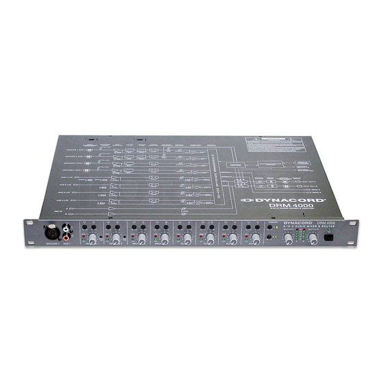
- Page 1 OWNER’S MANUAL DRM 4000 8-IN-2 AUDIO MIXER & ROUTER...
-
Page 2: Important Safety Instructions
IMPORTANT SAFETY INSTRUCTIONS Read these instructions. Keep these instructions. Heed all warnings. Follow all instructions. Do not use this apparatus near water. Clean only with a dry cloth. Do not block any of the ventilation openings. Install in accordance with the manufacturer’s instructions. Install only in rack with back cover. -
Page 3: Table Of Contents
1.1 DRM 4000 Characteristics ........1-4... -
Page 4: Introduction
INTRODUCTION 1. INTRODUCTION First of all, we like to thank you for and congratulate you on buying a DYNACORD DRM 4000 8-in-2 Audio Mixer & Router. To ensure optimal performance and to minimize the risk of damaging the appliance through erroneous operation, please make sure to read this owner’s manual carefully before operating the DRM 4000. -
Page 5: Unpacking And Warranty
Power-on delay: relay switching to prevent audible power-on / off switching noise. Enclosure: 19" / 1HU. This owner’s manual contains lots of valuable information about the DRM 4000. So please keep it at a safe place for further reference. 1.2 Unpacking and Warranty Carefully open the packaging and take out the DRM 4000. -
Page 6: Controls And Connections
CONTROLS AND CONNECTIONS 2. CONTROLS AND CONNECTIONS 2.1 Front Panel 1, Socket MIC/LINE 1 Electronically balanced XLR-input on the front panel for the connection of microphones or other signal sources. This socket is connected parallel to the MIC/LINE 1 input on the appliance’s rear panel. Gain, Pad and phantom power settings have to be performed on the rear panel. - Page 7 10 dB within an indication range of 40 dB; the indicators signal the individual levels at the outputs OUT A and OUT B in dBu. To prevent the occurrence of distortion, set the output levels of the DRM 4000 so that at the highest signal peaks the top LED’s of the chains are not lit (+20 dBu).
-
Page 8: Rear Panel
For details on the pin-assignment, please refer to chapter 4.3.3. 19, Master Outputs OUT A / B These are the two balanced XLR-type outputs of the DRM 4000. They can be used as L/R-stereo or as two separate monaural outputs, depending on the configuration of the DRM4000. - Page 9 Therefore, these outputs can be utilized for easy expanding / cascading several DRM 4000. 21, MIX IN input This unbalanced stereo/dual input can be used connecting another mixer or an additional DRM 4000 allowing easy expanding / cascading. 22, MIX IN control This control allows matching the level of the input signal to the MIX IN input.
-
Page 10: Quick Start
DRM 4000, please refer to the corresponding paragraph in the handbook. POWER SUPPLY Connect the DRM 4000 to a 24 V DC power source via the 6.3mm flat-connectors (14) on the rear panel. AUDIO CONNECTIONS Before integrating and initially operating the DRM 4000 in your PA-system, you should determine which system configuration you are using. -
Page 11: Installation And Connections
For operating the appliance, connect its power supply via the flat-con- nectors on the rear panel to a 24 V DC power source. When incorporating the DRM 4000 in a PA or intercom system, using the already present 24 V supply voltage is recommended. For including the DRM 4000 in other applications, please use the optionally available mains adapter (NRS 90257). -
Page 12: Aux And Mix In Inputs
MASTER outputs are typically connected to the inputs of an external power amplifier. When incorporating the DRM 4000 in an intercom system, the MASTER outputs are connected to the inputs of the consecutive central unit (e.g. DPM 4000 or mixer / router). -
Page 13: Control Inputs
As shipped, the configurations of the eight control inputs have been factory-pre-programmed for using the DRM 4000 in a multitude of applications. For further detail, please refer to chapter 8 and to the additional information sheet “DRM 4000 FACTORY CONFIGURATION”. -
Page 14: Initial Operation
5. INITIAL OPERATION 5.1 Power-On Operation The POWER-switch (12) switches the power of the DRM 4000 on. The ON-LED (13) starts to light and after a short period of initialization (approx. two seconds), the DRM 4000 is ready for operation. When switching the DRM 4000 on for the first time, it is factory-pre-configured for 8-in-2-mixer operation. -
Page 15: Level Adjustment For Aux Inputs
NOTE: If the input signal is not present at the master outputs, check the following: Are the master controls (10) open? Has the corresponding MIC/LINE input been assigned to one or both output channels? Please mind and compare your actual setting and the selected configuration! Is ducking control active (see ducking indicators (9)) and does this maybe affect your input signal? 5.2.2 Level Adjustment for AUX-inputs The four AUX-inputs are provided via two unbalanced RCA-type sockets each, which lets you connect... -
Page 16: Special Features Of The Drm 4000
The master signal of all input channels is controlled using the master controls at the DRM 4000 that is last in chain. The corresponding outputs are OUT A and OUT B of that “last” DRM 4000. When employing the MIX IN input for this special purpose, set the MIX IN control to its 0 dB-mark. -
Page 17: Using The Unit Together With The Dpm 4000
SPECIAL FEATURES OF THE DRM 4000 6.4 Using The Unit Together With The DPM 4000 The DRM 4000 is an ideal inputs extension for the DPM 4000. Audio connections between the two units are established using balanced cables with XLR-type connectors. -
Page 18: Software Editor Drm 4000
- Follow the instructions during the installation routine. 7.3 PC - DRM 4000 Connection Check your PC for available COM-ports that are not assigned to any other application. The DRM 4000 Editor Software allows choosing between COM1 to COM8. Use a custom RS-232 cable (5-pin D-type, plug-socket, 1:1) for connecting the chosen COM-port on your computer to the RS-232 interface-port on the rear panel of the DRM 4000. -
Page 19: Software Description
The DYNACORD DRM 4000 Editor software provides an extremely easy and comfortable manner for configuring, controlling and monitoring the DRM 4000. It is possible to load, save or transfer any number of DRM 4000 configurations. Additionally, reading the actual configuration of a DRM 4000 and storing it on disk is possible as well. -
Page 20: Basic Configuration
The parameters to be set here represent the mixer’s basic configuration, which is always active when none of the DRM 4000’s contact inputs are engaged. When the DRM 4000 is connected to your PC, using the “Online Control”-soft key allows establishing any settings in real-time. - Page 21 Enabling or disabling the function is possible. Note: Ducking and Priority Override settings can be made on the front panel of the DRM 4000. For further detail, please refer to the corresponding chapter of this owner’s manual.
- Page 22 Setting each control input parameter to “No Change” is also possible. When activating a control input, all parameters that are set to “No Change” are not altered. When the DRM 4000 is connected to your PC, using the “Online Control”-soft key allows establishing any settings in real-time.
-
Page 23: Control Inputs
7.4.5 Online Control / Status This window allows remotely controlling and monitoring the DRM 4000 in real-time. It also offers the possibility to test the active control input configuration without the need for additional hardware. An active RS-232-connection between your computer and the DRM 4000 is necessary to be able to access this functionality. -
Page 24: Configuring The Drm 4000
The DRM 4000’s BASIC CONFIGURATION is active whenever no CONTROL INPUT is connected to ground. The DRM 4000’s factory-pre-set BASIC CONFIGURATION is 8-in-2 mixer. The following example shows the wiring for a typical 8-in-2 mixer application of the DRM 4000. The freely programmable CONTROL INPUTS allow switching to other configurations. Therefore, the corresponding CONTROL INPUT needs to be connected to ground. - Page 25 Legend to the table on the DRM 4000 FACTORY CONFIGURATION leaflet: BASIC CONFIGURATION: CONTACT 1-8: PRIORITY: Routing: Mono A Mono B Dual Stereo No Change Mute: No Mute Mute On No Change VCA: Priority Override: Enable Disable Ducking: Ducking Active...
-
Page 26: Internal Settings / Extensions
Leave all servicing and maintenance to the experienced and qualified service technician. To be able to make changes to internal settings or retrofit extension you have to open the DRM 4000. To do so, please proceed as follows: 1. -
Page 27: Direct Outputs
9.1.1 Low Cut Filter The four MIC/LINE-inputs provide switch-able Low Cut filter (85 Hz / 12 dB per octave), which cut-off frequencies below 85 Hz. The use of the Low Cut filters is especially recommendable for microphone applications, effectively eliminating low-frequency feedback and ambient sound as well as popping sounds, which results in increased vocal intelligibility. -
Page 28: Aux Sensitivity Selection
For adjusting the limiters in the input channels MIC/LINE 1 and 2, please proceed as follows: – Open the DRM 4000 by following the description provided in the preamble to chapter 9. – Locate the trimmers VR1D (MIC/LINE 1) and VR2D (MIC/LINE 2) on the left-hand side of the main printed board assembly. -
Page 29: How To Install Extensions
1 x Input Transformer DCN340955 Installation Instructions NRS 90233: 1. Turn off the power of the DRM 4000 and open the cover plate as described before. 2. For installation of the transformer you first have to remove the printed board assembly 80478 (MAIN BOARD). -
Page 30: How To Install The Output Transformer (Nrs 90227)
1 x Output Transformer DCN354596 Installation Instructions NRS 90227: 1. Turn off the power of the DRM 4000 and open the cover plate as described before. 2. For installation of the transformer you first have to remove the printed board assembly 80478 (MAIN BOARD). -
Page 31: How To Install Interface-Boards
2 x Locking-screws Installation Instructions NRS 90256, NRS 90258: 1. Turn off the power of the DRM 4000 and open the cover plate as described before. 2. Loosen the blind on the rear panel (2 screws on the rear). 3. Install the extension printed board assembly replacing the blind. -
Page 32: Specifications
SPECIFICATIONS 10. SPECIFICATIONS 10.1 Specifications Supply Voltage Nom. Power Consumption (24 V) Max. Power Consumption (24 V) Audio Inputs MIC/LINE Inputs Nom. Input Level MIC: LINE: Max. Input Level MIC: LINE: Input Impedance MIC: LINE: Common Mode Rejection Limiter Operating Range AUX Inputs Nom. -
Page 33: User Configuration
SPECIFICATIONS 10.2 User Configuration 10-2... - Page 34 SPECIFICATIONS 10-3...
-
Page 35: Block Diagram
SPECIFICATIONS 10.3 Block diagram 10-4... -
Page 36: Rs-232 Interface - Programmer's Instructions
SPECIFICATIONS 10.4 RS-232 Interface - Programmer’s Instructions Controlling the DRM 4000 from a media control desk or from an intercom system is possible via the serial RS-232 interface (NRS 90258, 121 790) using simple ASCII-commands. The serial RS-232 interface is set to a baud rate of 19200 with 8 data bits, 1 stop bit, no parity, Xon/Xoff protocol. - Page 37 10.4.2 Online-Access to all Parameters Via RS-232 connection and using REMOTE-commands provides direct access to all DRM 4000 parame- ters, like routing, VCA, priority override, ducking, mute, etc. Controlling the unit is possible parallel to any other control method (hardware contact switching, software contact switching, external VCA-control), with any individual priority being recognized.
-
Page 38: Dimensions
SPECIFICATIONS 10.5 Dimensions 10-7... -
Page 39: Warranty
The warranty does not cover damage that results from improper or inadequate treatment or maintenance. In case of alteration or unauthorized repairs, the warranty is automatically terminated. Printed in Germany 16. 07. 2001 / 358 627 Internet: http:// www.dynacord.de...