Table of Contents
Advertisement
Quick Links
Advertisement
Table of Contents

Related Manuals for Martin Audio DX1.5


Summary of Contents for Martin Audio DX1.5
- Page 2 Editing Audio Parameters – Input Channels Editing Audio Parameters – Output Channels Input Ganging and Output Ganging Memory Structure Loading new software via a pc AES Inputs Warranty All material © 2009. Martin Audio Ltd. Subject to change without notice.
- Page 3 Please think of our environment. When the product has reached the end of its useful life, please dispose of it responsibly through a recycling centre. All material © 2009. Martin Audio Ltd. Subject to change without notice.
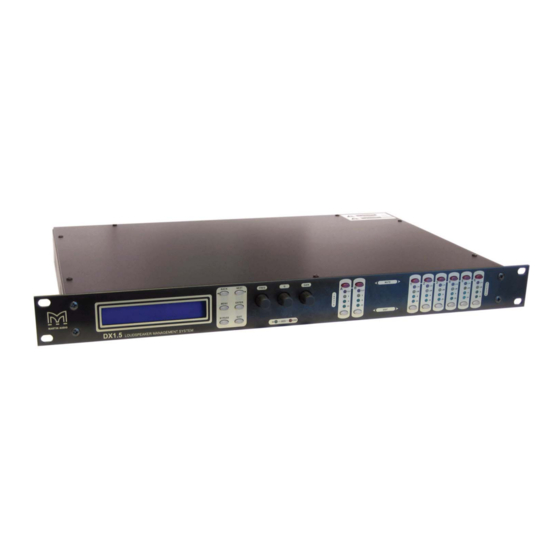
- Page 4 Introduction The DX1.5 is a powerful DSP based audio processor, ideally suited for install applications, where they combine the functions of a multitude of conventional products in a compact 1U unit. To achieve this, the unit’s have inputs and outputs which can be configured in a selection of basic crossover modes.
- Page 5 To swap delay time units, enter System Sub-menu, select Delay Time / Distance, and select required readout units. If you press an EDIT key the corresponding channels routed to / from that channel will flash. All material © 2009. Martin Audio Ltd. Subject to change without notice.
- Page 6 Make sure you have a full set of .bin files before proceeding so that you can reload your original presets if you need to. If you are not familiar with the Martin Audio DX1.5, please read the DX1.5 User Guide. You should have extracted the following files to a suitable folder on your hard drive: MartinFlashLoader.exe –...
- Page 7 Set the Serial Port Speed to 38400. The bottom right hand window should indicate Good Response. If the Serial Speed number is not set to 38400 to match the DX1.5 speed, the software lower right window may indicate No Response.
- Page 8 Make sure that the Serial port Speed on your pc screen is set to 38400 to match the DX1.5. If that fails to fix the problem, try adjusting the Com (Serial Port) number and clicking the Connect button again. It is usually quicker to do this by trial and error as Com port numbering...
- Page 9 You’ll see the green block writing progress bar proceeding from left to right on the DX1.5 front panel you’ll see graphics shuffling from right to left…followed by an indicator test (all LEDs on)…and a short delay…and then a wake-up procedure.
- Page 10 Back Next buttons or the Frequency knob. Note that the DX1.5 will default to its previous condition if the above operations are not completed and no buttons are pressed for 20 – 30 seconds. Input parameters Input parameters are not usually specified within standard Martin Audio presets – hence the Crossover only selection above.
-
Page 11: System Configurations
There are a large number of Martin Audio factory presets and configurations and these are being expanded all the time. It is always sensible to check your DX1.5 output channel allocations for the particular preset you have chosen to use before patching your system. This will ensure that the appropriate band is being routed to each loudspeaker section. - Page 12 The two status LEDs indicate that AES inputs have been selected and Error. Inputs A & B - meters show dB from clipping point of the analogue to digital converters. All material © 2009. Martin Audio Ltd. Subject to change without notice.
- Page 13 Important - Always replace the fuse with the correct type and rating as shown on the rear panel legend. Mains Inlet - connected via a standard IEC socket. External - 9 pin D-type connector for preset loading via RS232 PC link. See later for DX1.5 preset loading instructions.
- Page 14 Repeat the above directions to return to menu mode. Routing Options and Processing Blocks Due to the completely new DSP platform, the routing possibilities within the DX1.5 have been made completely flexible, with a matrix available allowing any combination of inputs to be routed to any output.
- Page 15 Design a Crossover -> Clear Settings : No * Press ENTER again. The wizard will continue, and if the routing has been changed, all outputs will be muted on exit. All material © 2009. Martin Audio Ltd. Subject to change without notice.
- Page 16 Changing the filter type is achieved by pressing ENTER during editing any particular band. Frequency Gain The display will show, for instance Input A PEQ:1<> 1k00Hz Q=3.0 0.0dB All material © 2009. Martin Audio Ltd. Subject to change without notice.
- Page 17 High/Low Freq. Overlap! will be displayed. Note that to access the 48dB/Octave filters, parametric bands 6 & 7 need to be bypassed, or set to 0dB. All material © 2009. Martin Audio Ltd. Subject to change without notice.
- Page 18 Changing the filter type is achieved by pressing BYPASS to bypass the filter and then pressing ENTER during editing any particular band. Freq Gain All material © 2009. Martin Audio Ltd. Subject to change without notice.
- Page 19 The method of linking inputs or outputs together during editing is achieved in the same way, so only crossover (output) ganging will be explained here. Having selected Crossover Ganging from the menu under the Crossover Sub-Menu, the current ganging set-up will be displayed. All material © 2009. Martin Audio Ltd. Subject to change without notice.
- Page 20 So, to gang outputs 1 and 5, press MUTE 5 then EDIT 1 – the display will show <-Crossover Ganging Gang Output 5 with 1 Ganging is cleared by selecting Ganging=None from the initial choices given above. All material © 2009. Martin Audio Ltd. Subject to change without notice.
- Page 21 The Input Ganging procedure is identical to the crossover ganging, selectable under the Input Sub-Menu. Memory Structure The DX1.5 has its memories split into sections, allowing independent recall of crossover settings (i.e. all parameters associated with outputs), and input settings. There are, therefore, three types of memory available...
- Page 22 AES Inputs DX1.5 units have AES input facilities (via input XLR A) built in as standard. This allows the unit to receive digital audio directly Input selection is via a recessed switch on the rear panel of the unit, near output 1. A red LED inside this aperture illuminates to show that the AES digital inputs have been selected.
- Page 23 1 year from the date of original purchase. During the warranty period Martin Audio will, at its discretion, either repair or replace products which prove to be defective provided that the product is returned in its original packaging, shipping prepaid, to an authorised Martin Audio service agent or distributor.